EP0345126A1 - Kühlungs- oder Heizungsvorrichtung für z.B. Gasleitungen - Google Patents
Kühlungs- oder Heizungsvorrichtung für z.B. Gasleitungen Download PDFInfo
- Publication number
- EP0345126A1 EP0345126A1 EP89401436A EP89401436A EP0345126A1 EP 0345126 A1 EP0345126 A1 EP 0345126A1 EP 89401436 A EP89401436 A EP 89401436A EP 89401436 A EP89401436 A EP 89401436A EP 0345126 A1 EP0345126 A1 EP 0345126A1
- Authority
- EP
- European Patent Office
- Prior art keywords
- envelope
- pipes
- tube
- cooling
- aforementioned
- Prior art date
- Legal status (The legal status is an assumption and is not a legal conclusion. Google has not performed a legal analysis and makes no representation as to the accuracy of the status listed.)
- Granted
Links
- 238000001816 cooling Methods 0.000 title claims abstract description 21
- 238000010438 heat treatment Methods 0.000 title claims abstract description 17
- 239000012530 fluid Substances 0.000 claims abstract description 10
- 239000004033 plastic Substances 0.000 claims abstract description 4
- 229920003023 plastic Polymers 0.000 claims abstract description 4
- XLYOFNOQVPJJNP-UHFFFAOYSA-N water Substances O XLYOFNOQVPJJNP-UHFFFAOYSA-N 0.000 claims description 7
- 238000006243 chemical reaction Methods 0.000 claims description 6
- 239000011810 insulating material Substances 0.000 claims description 6
- 238000003303 reheating Methods 0.000 claims description 6
- 239000001913 cellulose Substances 0.000 claims description 3
- 229920002678 cellulose Polymers 0.000 claims description 3
- 239000000203 mixture Substances 0.000 claims description 3
- 230000001143 conditioned effect Effects 0.000 claims description 2
- 238000005553 drilling Methods 0.000 claims description 2
- 239000004744 fabric Substances 0.000 abstract description 3
- 239000000463 material Substances 0.000 description 5
- 239000000853 adhesive Substances 0.000 description 4
- 238000004804 winding Methods 0.000 description 3
- WCUXLLCKKVVCTQ-UHFFFAOYSA-M Potassium chloride Chemical compound [Cl-].[K+] WCUXLLCKKVVCTQ-UHFFFAOYSA-M 0.000 description 2
- 239000003795 chemical substances by application Substances 0.000 description 2
- 239000012809 cooling fluid Substances 0.000 description 2
- 229940082150 encore Drugs 0.000 description 2
- 238000003780 insertion Methods 0.000 description 2
- 230000037431 insertion Effects 0.000 description 2
- 238000004519 manufacturing process Methods 0.000 description 2
- 229910052751 metal Inorganic materials 0.000 description 2
- 239000002184 metal Substances 0.000 description 2
- 238000000034 method Methods 0.000 description 2
- 240000008042 Zea mays Species 0.000 description 1
- 230000001133 acceleration Effects 0.000 description 1
- 229920000704 biodegradable plastic Polymers 0.000 description 1
- 238000007664 blowing Methods 0.000 description 1
- 239000002826 coolant Substances 0.000 description 1
- 239000006260 foam Substances 0.000 description 1
- 238000005304 joining Methods 0.000 description 1
- 230000014759 maintenance of location Effects 0.000 description 1
- 239000002985 plastic film Substances 0.000 description 1
- 229920006255 plastic film Polymers 0.000 description 1
- 239000001103 potassium chloride Substances 0.000 description 1
- 235000011164 potassium chloride Nutrition 0.000 description 1
- 238000009958 sewing Methods 0.000 description 1
- 238000003466 welding Methods 0.000 description 1
Images

Classifications
-
- F—MECHANICAL ENGINEERING; LIGHTING; HEATING; WEAPONS; BLASTING
- F16—ENGINEERING ELEMENTS AND UNITS; GENERAL MEASURES FOR PRODUCING AND MAINTAINING EFFECTIVE FUNCTIONING OF MACHINES OR INSTALLATIONS; THERMAL INSULATION IN GENERAL
- F16L—PIPES; JOINTS OR FITTINGS FOR PIPES; SUPPORTS FOR PIPES, CABLES OR PROTECTIVE TUBING; MEANS FOR THERMAL INSULATION IN GENERAL
- F16L47/00—Connecting arrangements or other fittings specially adapted to be made of plastics or to be used with pipes made of plastics
- F16L47/02—Welded joints; Adhesive joints
- F16L47/03—Welded joints with an electrical resistance incorporated in the joint
-
- B—PERFORMING OPERATIONS; TRANSPORTING
- B29—WORKING OF PLASTICS; WORKING OF SUBSTANCES IN A PLASTIC STATE IN GENERAL
- B29C—SHAPING OR JOINING OF PLASTICS; SHAPING OF MATERIAL IN A PLASTIC STATE, NOT OTHERWISE PROVIDED FOR; AFTER-TREATMENT OF THE SHAPED PRODUCTS, e.g. REPAIRING
- B29C65/00—Joining or sealing of preformed parts, e.g. welding of plastics materials; Apparatus therefor
- B29C65/02—Joining or sealing of preformed parts, e.g. welding of plastics materials; Apparatus therefor by heating, with or without pressure
- B29C65/34—Joining or sealing of preformed parts, e.g. welding of plastics materials; Apparatus therefor by heating, with or without pressure using heated elements which remain in the joint, e.g. "verlorenes Schweisselement"
- B29C65/3404—Joining or sealing of preformed parts, e.g. welding of plastics materials; Apparatus therefor by heating, with or without pressure using heated elements which remain in the joint, e.g. "verlorenes Schweisselement" characterised by the type of heated elements which remain in the joint
- B29C65/342—Joining or sealing of preformed parts, e.g. welding of plastics materials; Apparatus therefor by heating, with or without pressure using heated elements which remain in the joint, e.g. "verlorenes Schweisselement" characterised by the type of heated elements which remain in the joint comprising at least a single wire, e.g. in the form of a winding
-
- B—PERFORMING OPERATIONS; TRANSPORTING
- B29—WORKING OF PLASTICS; WORKING OF SUBSTANCES IN A PLASTIC STATE IN GENERAL
- B29C—SHAPING OR JOINING OF PLASTICS; SHAPING OF MATERIAL IN A PLASTIC STATE, NOT OTHERWISE PROVIDED FOR; AFTER-TREATMENT OF THE SHAPED PRODUCTS, e.g. REPAIRING
- B29C66/00—General aspects of processes or apparatus for joining preformed parts
- B29C66/01—General aspects dealing with the joint area or with the area to be joined
- B29C66/03—After-treatments in the joint area
- B29C66/034—Thermal after-treatments
- B29C66/0342—Cooling, e.g. transporting through welding and cooling zone
-
- B—PERFORMING OPERATIONS; TRANSPORTING
- B29—WORKING OF PLASTICS; WORKING OF SUBSTANCES IN A PLASTIC STATE IN GENERAL
- B29C—SHAPING OR JOINING OF PLASTICS; SHAPING OF MATERIAL IN A PLASTIC STATE, NOT OTHERWISE PROVIDED FOR; AFTER-TREATMENT OF THE SHAPED PRODUCTS, e.g. REPAIRING
- B29C66/00—General aspects of processes or apparatus for joining preformed parts
- B29C66/01—General aspects dealing with the joint area or with the area to be joined
- B29C66/05—Particular design of joint configurations
- B29C66/10—Particular design of joint configurations particular design of the joint cross-sections
- B29C66/11—Joint cross-sections comprising a single joint-segment, i.e. one of the parts to be joined comprising a single joint-segment in the joint cross-section
- B29C66/112—Single lapped joints
- B29C66/1122—Single lap to lap joints, i.e. overlap joints
-
- B—PERFORMING OPERATIONS; TRANSPORTING
- B29—WORKING OF PLASTICS; WORKING OF SUBSTANCES IN A PLASTIC STATE IN GENERAL
- B29C—SHAPING OR JOINING OF PLASTICS; SHAPING OF MATERIAL IN A PLASTIC STATE, NOT OTHERWISE PROVIDED FOR; AFTER-TREATMENT OF THE SHAPED PRODUCTS, e.g. REPAIRING
- B29C66/00—General aspects of processes or apparatus for joining preformed parts
- B29C66/50—General aspects of joining tubular articles; General aspects of joining long products, i.e. bars or profiled elements; General aspects of joining single elements to tubular articles, hollow articles or bars; General aspects of joining several hollow-preforms to form hollow or tubular articles
- B29C66/51—Joining tubular articles, profiled elements or bars; Joining single elements to tubular articles, hollow articles or bars; Joining several hollow-preforms to form hollow or tubular articles
- B29C66/52—Joining tubular articles, bars or profiled elements
- B29C66/522—Joining tubular articles
- B29C66/5221—Joining tubular articles for forming coaxial connections, i.e. the tubular articles to be joined forming a zero angle relative to each other
-
- B—PERFORMING OPERATIONS; TRANSPORTING
- B29—WORKING OF PLASTICS; WORKING OF SUBSTANCES IN A PLASTIC STATE IN GENERAL
- B29C—SHAPING OR JOINING OF PLASTICS; SHAPING OF MATERIAL IN A PLASTIC STATE, NOT OTHERWISE PROVIDED FOR; AFTER-TREATMENT OF THE SHAPED PRODUCTS, e.g. REPAIRING
- B29C66/00—General aspects of processes or apparatus for joining preformed parts
- B29C66/50—General aspects of joining tubular articles; General aspects of joining long products, i.e. bars or profiled elements; General aspects of joining single elements to tubular articles, hollow articles or bars; General aspects of joining several hollow-preforms to form hollow or tubular articles
- B29C66/51—Joining tubular articles, profiled elements or bars; Joining single elements to tubular articles, hollow articles or bars; Joining several hollow-preforms to form hollow or tubular articles
- B29C66/52—Joining tubular articles, bars or profiled elements
- B29C66/522—Joining tubular articles
- B29C66/5229—Joining tubular articles involving the use of a socket
-
- B—PERFORMING OPERATIONS; TRANSPORTING
- B29—WORKING OF PLASTICS; WORKING OF SUBSTANCES IN A PLASTIC STATE IN GENERAL
- B29C—SHAPING OR JOINING OF PLASTICS; SHAPING OF MATERIAL IN A PLASTIC STATE, NOT OTHERWISE PROVIDED FOR; AFTER-TREATMENT OF THE SHAPED PRODUCTS, e.g. REPAIRING
- B29C66/00—General aspects of processes or apparatus for joining preformed parts
- B29C66/80—General aspects of machine operations or constructions and parts thereof
- B29C66/81—General aspects of the pressing elements, i.e. the elements applying pressure on the parts to be joined in the area to be joined, e.g. the welding jaws or clamps
- B29C66/814—General aspects of the pressing elements, i.e. the elements applying pressure on the parts to be joined in the area to be joined, e.g. the welding jaws or clamps characterised by the design of the pressing elements, e.g. of the welding jaws or clamps
- B29C66/8145—General aspects of the pressing elements, i.e. the elements applying pressure on the parts to be joined in the area to be joined, e.g. the welding jaws or clamps characterised by the design of the pressing elements, e.g. of the welding jaws or clamps characterised by the constructional aspects of the pressing elements, e.g. of the welding jaws or clamps
- B29C66/81471—General aspects of the pressing elements, i.e. the elements applying pressure on the parts to be joined in the area to be joined, e.g. the welding jaws or clamps characterised by the design of the pressing elements, e.g. of the welding jaws or clamps characterised by the constructional aspects of the pressing elements, e.g. of the welding jaws or clamps being a wrap-around tape or band
-
- F—MECHANICAL ENGINEERING; LIGHTING; HEATING; WEAPONS; BLASTING
- F16—ENGINEERING ELEMENTS AND UNITS; GENERAL MEASURES FOR PRODUCING AND MAINTAINING EFFECTIVE FUNCTIONING OF MACHINES OR INSTALLATIONS; THERMAL INSULATION IN GENERAL
- F16L—PIPES; JOINTS OR FITTINGS FOR PIPES; SUPPORTS FOR PIPES, CABLES OR PROTECTIVE TUBING; MEANS FOR THERMAL INSULATION IN GENERAL
- F16L53/00—Heating of pipes or pipe systems; Cooling of pipes or pipe systems
- F16L53/30—Heating of pipes or pipe systems
- F16L53/32—Heating of pipes or pipe systems using hot fluids
-
- F—MECHANICAL ENGINEERING; LIGHTING; HEATING; WEAPONS; BLASTING
- F16—ENGINEERING ELEMENTS AND UNITS; GENERAL MEASURES FOR PRODUCING AND MAINTAINING EFFECTIVE FUNCTIONING OF MACHINES OR INSTALLATIONS; THERMAL INSULATION IN GENERAL
- F16L—PIPES; JOINTS OR FITTINGS FOR PIPES; SUPPORTS FOR PIPES, CABLES OR PROTECTIVE TUBING; MEANS FOR THERMAL INSULATION IN GENERAL
- F16L53/00—Heating of pipes or pipe systems; Cooling of pipes or pipe systems
- F16L53/70—Cooling of pipes or pipe systems
-
- H—ELECTRICITY
- H05—ELECTRIC TECHNIQUES NOT OTHERWISE PROVIDED FOR
- H05B—ELECTRIC HEATING; ELECTRIC LIGHT SOURCES NOT OTHERWISE PROVIDED FOR; CIRCUIT ARRANGEMENTS FOR ELECTRIC LIGHT SOURCES, IN GENERAL
- H05B3/00—Ohmic-resistance heating
- H05B3/40—Heating elements having the shape of rods or tubes
- H05B3/54—Heating elements having the shape of rods or tubes flexible
- H05B3/58—Heating hoses; Heating collars
-
- B—PERFORMING OPERATIONS; TRANSPORTING
- B29—WORKING OF PLASTICS; WORKING OF SUBSTANCES IN A PLASTIC STATE IN GENERAL
- B29C—SHAPING OR JOINING OF PLASTICS; SHAPING OF MATERIAL IN A PLASTIC STATE, NOT OTHERWISE PROVIDED FOR; AFTER-TREATMENT OF THE SHAPED PRODUCTS, e.g. REPAIRING
- B29C66/00—General aspects of processes or apparatus for joining preformed parts
- B29C66/01—General aspects dealing with the joint area or with the area to be joined
- B29C66/02—Preparation of the material, in the area to be joined, prior to joining or welding
- B29C66/024—Thermal pre-treatments
- B29C66/0242—Heating, or preheating, e.g. drying
Definitions
- the present invention essentially relates to a device for cooling or heating pipes intended for transporting any fluid and such as, for example, gas.
- the two pipes to be connected are of course held by special and suitable support means.
- the first problem is that of the acceleration of the cooling after electrowelding, so as to be able to quickly release the support and holding devices for the pipes, which would make it possible to shorten the downtime of the equipment and therefore reduce the overall cost of the operation.
- the present invention aims to solve the problems and achieve the above goals, by proposing a particularly simple, reliable, inexpensive cooling or reheating device which can be implemented very quickly and very conveniently on a site.
- the subject of the invention is a device for cooling or heating pipes intended for transporting any fluid, such as gas for example, and connected by means of an electroweldable sleeve or the like, characterized by least a removable casing with which is associated a cooling or heating means and which surrounds either the connection zone with sleeve, pipes, or the free end of these pipes before their connection.
- the winding of the envelope which may be lost or reusable, around the connection area of two pipes or around the end of one of the pipes, will be sufficient to effectively ensure using an appropriate agent to cool or reheat the wrapped area.
- the aforementioned envelope is made of canvas or plastic and the end of at least one tube for supplying cooling or heating fluid is fixed to said envelope so as to open tangentially to the one side of this envelope.
- the aforementioned supply tube is preferably fixed orthogonally to one of the sides of the envelope which has for example a rectangular shape, so that after mounting of the envelope around the pipe or pipes, the flow of fluid delivered by the tube is injected tangentially to the pipes and perpendicular to their axis.
- the aforementioned envelope comprises two pockets respectively containing water and a product which, mixed with water, produces an exothermic or endothermic reaction.
- These two pockets are advantageously arranged between an outer thermally insulating envelope and an inner cellulose envelope capable of retaining the mixture of products in the two pockets after drilling thereof.
- the envelope made of thermally insulating material, comprises on one of its faces at least one open pocket and which can removably receive a cooling or reheating product preferably previously conditioned.
- the aforementioned envelope is provided on two opposite sides and on its two faces with self-fastening strips, or else hooking tabs are provided on two opposite edges of the envelope, or still masses are provided on these two opposite edges.
- the envelope placed around the connection area of the pipes will be firmly maintained in its rolled up or mounted position around the area to be cooled or reheated.
- the envelope in the case where the envelope is mounted on the free end of a pipe, it is integral from one of the ends of a tube capable of receiving a product, such as for example a heating product, this tube being introduced into the end of the pipe which is covered by said envelope.
- a product such as for example a heating product
- the envelope is made of a thermally insulating material and it can be opened and closed over its entire length by means of an appropriate system.
- the aforementioned tube may include orifices for the evacuation of calories, and its two ends may be provided with means for guiding the introduction of the tube into the end of the pipe to be heated.
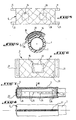
- an envelope 4 is used, surrounding the connection area and into which a coolant from this area is injected by a tube 5, it being understood that the reheating of said zone, before connection, could also be carried out in the same way by injecting a reheating agent into the envelope.
- the envelope 4 is, in the deployed state, in the form of a strip of fabric for example, and the tube 5 for supplying cooling fluid, such as air, is fixed to the 'envelope 4 so as to open tangentially, as seen in 6, to one of the faces or inner face 7 of the envelope.
- the tube 5 can be fixed in any suitable manner, by sewing for example, as seen diagrammatically at 8, on the internal face 7 of the casing 4.
- the envelope or strip 4 has, according to the embodiment shown, a substantially rectangular shape, and the tube 5 is fixed orthogonally to one of the short sides of the strip 4 so that after mounting around the pipes 1, the flow of cooling fluid delivered by the through end 6 is injected tangentially to the conduits 1 and perpendicular to their axis, as can be understood by referring to FIG. 1.
- FIG. 2 shows self-latching strips 9, for example known under the trade name "Velcro", provided on the two opposite long sides of the strip or envelope 4 and on its two faces, so that after winding the strip around the pipes 1, this strip will be firmly held in its wound position.
- Velcro self-latching strips 9
- the envelope 4 is quite simply produced from a film of biodegradable plastic material 10 which can be buried at the time of backfilling. of the trench after connecting the pipes.
- a tube 5 connectable to a source of compressed air for example (not shown).
- the two long sides of the strip 4 may, as in the embodiment of FIG. 2, include a gathering shown schematically at 12 and giving the film 10 a slight hollow shape making it possible to absorb the volume represented by the welding sleeve 3, without causing the said film to break.
- This film may also include small orifices 13 to allow the compressed air exiting through the through end 6 of the tube 5 to escape, so as not to damage the film when it is in the wound state. This was not necessary in the embodiment of Figure 2, since, by nature, the fabric constituting the envelope 4 is permeable to air.
- the casing 4 again forms a strip here, but this strip no longer comprises a tube for supplying cooling or heating fluid, but carries two bags 13, 14 respectively containing water and a product, such as for example potassium chloride, which, mixed with water, produces a chemical reaction.
- a product such as for example potassium chloride
- the chemical reaction can be endothermic or exothermic.
- the pockets 13 and 14 are arranged between an outer thermally insulating envelope 15 and an inner cellulose envelope 16 capable of retaining the mixture of products in the two pockets 13 and 14 after these two pockets have been pierced.
- the casing 4 is not reusable and can consist mainly of biodegradable materials.
- two opposite edges of the envelope or band 4 carrying the pockets 13 and 14 may have hooking tabs and for example self-adhesive 11, to ensure the assembly in the wound position of the envelope 4 around of the connection area of the pipes 1.
- hooking tabs for example self-adhesive 11
- self-fastening strips as described in connection with FIG. 2, without thereby departing from the scope of the 'invention.
- the envelope 4 carries on its inner face a pocket 17 which, unlike the embodiment of FIG. 4, is open, as can be seen in 18.
- This pocket 17 can receive, in a removable manner, a cooling or reheating product itself -even preferably packaged and contained in another pocket shown diagrammatically at 19 in FIG. 6.
- the open pocket 17 is fixed, for example sewn, on a band 20 forming an envelope, which is made of a thermally insulating material.
- Two opposite edges of the strip 20 may contain weights 21 in the form of metal bars, so that the casing 4 can easily and conveniently be placed astride and therefore mounted on the connection area of the conduits 1.
- the envelope 4 according to FIG. 6 is obviously reusable, in the sense that the pocket 19 is open and will easily allow the removal and insertion of materials that generate calories or frigories for a certain time, and as is known per se .
- FIGS. 7 and 8 describe yet another embodiment of the device in accordance with the principles according to this invention.
- This device comprises a casing 4 which here is mounted on the free end of a pipe 1 which is to be preheated before making its connection to another pipe.
- This envelope 4 made of a thermally insulating material, is integral, as can be seen in FIG. 7, with one 22 of the two ends 22, 23 of a tube 24 capable of receiving a heating product and being inserted into the end of line 1.
- the tube 24 has orifices 25 allowing the evacuation of the calories generated by the product inside this tube, the ends 22 and 23 of which each have a foam cylinder for example 26 allowing the guidance inside the pipe 1 and also serving to limit the heating zone.
- the tube or sheath 24 with the product that it contains is introduced inside the pipe 1, and then this pipe is covered with the casing 4 to avoid heat losses towards the outside.
- the envelope 4 comprises, over its entire length, a means, such as that known for example under the name "zipper", identified at 27, so that the envelope 4 can be easily opened and closed to allow removal of the assembly from line 1 and final assembly after insertion of the assembly into said line.
- a means such as that known for example under the name "zipper”, identified at 27, so that the envelope 4 can be easily opened and closed to allow removal of the assembly from line 1 and final assembly after insertion of the assembly into said line.
- a device in the form of an envelope, therefore reusable or not, has therefore been produced according to the invention, making it possible to reliably and conveniently cool or reheat the connection zone of pipes or the pipes themselves, this device remaining of a very low cost and making it possible to achieve considerable savings in terms of the time of immobilization of the materials necessary for making the connection of the pipes, and also in terms of the time of the process of electroweld connection.
Landscapes
- Engineering & Computer Science (AREA)
- Mechanical Engineering (AREA)
- General Engineering & Computer Science (AREA)
- Physics & Mathematics (AREA)
- Thermal Sciences (AREA)
- Lining Or Joining Of Plastics Or The Like (AREA)
- Thermotherapy And Cooling Therapy Devices (AREA)
- Thermal Insulation (AREA)
- Pipe Accessories (AREA)
Priority Applications (1)
| Application Number | Priority Date | Filing Date | Title |
|---|---|---|---|
| AT89401436T ATE75182T1 (de) | 1988-05-31 | 1989-05-25 | Kuehlungs- oder heizungsvorrichtung fuer z.b. gasleitungen. |
Applications Claiming Priority (2)
| Application Number | Priority Date | Filing Date | Title |
|---|---|---|---|
| FR8807245A FR2632050B1 (fr) | 1988-05-31 | 1988-05-31 | Dispositif de refroidissement ou de rechauffage de conduites destinees a transporter par exemple du gaz |
| FR8807245 | 1988-05-31 |
Publications (2)
| Publication Number | Publication Date |
|---|---|
| EP0345126A1 true EP0345126A1 (de) | 1989-12-06 |
| EP0345126B1 EP0345126B1 (de) | 1992-04-22 |
Family
ID=9366790
Family Applications (1)
| Application Number | Title | Priority Date | Filing Date |
|---|---|---|---|
| EP89401436A Expired - Lifetime EP0345126B1 (de) | 1988-05-31 | 1989-05-25 | Kühlungs- oder Heizungsvorrichtung für z.B. Gasleitungen |
Country Status (8)
| Country | Link |
|---|---|
| EP (1) | EP0345126B1 (de) |
| AT (1) | ATE75182T1 (de) |
| DE (2) | DE345126T1 (de) |
| DK (1) | DK261489A (de) |
| ES (1) | ES2016921T3 (de) |
| FR (1) | FR2632050B1 (de) |
| GR (2) | GR900300161T1 (de) |
| PT (1) | PT90701B (de) |
Cited By (2)
| Publication number | Priority date | Publication date | Assignee | Title |
|---|---|---|---|---|
| EP2733405A1 (de) * | 2012-11-16 | 2014-05-21 | Bayer MaterialScience AG | Flexibles, transportables Flächengebilde zur Dampfbeheizung von Rohrleitungen |
| WO2020236842A1 (en) * | 2019-05-21 | 2020-11-26 | Jason Fladoos | Flexible heating and cooling tape |
Families Citing this family (1)
| Publication number | Priority date | Publication date | Assignee | Title |
|---|---|---|---|---|
| CN112128483A (zh) * | 2020-09-26 | 2020-12-25 | 潍坊新力蒙水产技术有限公司 | 一种液氢真空输送管 |
Citations (3)
| Publication number | Priority date | Publication date | Assignee | Title |
|---|---|---|---|---|
| FR2169020A1 (de) * | 1972-01-27 | 1973-09-07 | Costa Allan | |
| GB2187815A (en) * | 1986-03-13 | 1987-09-16 | Wavecare Limited | Pipe freezing apparatus |
| DE8633676U1 (de) * | 1986-12-17 | 1987-09-17 | Hemstedt GmbH, 7129 Brackenheim | Rohrmanschettenheizung für Regeneinläufe |
-
1988
- 1988-05-31 FR FR8807245A patent/FR2632050B1/fr not_active Expired - Lifetime
-
1989
- 1989-05-25 EP EP89401436A patent/EP0345126B1/de not_active Expired - Lifetime
- 1989-05-25 DE DE198989401436T patent/DE345126T1/de active Pending
- 1989-05-25 ES ES198989401436T patent/ES2016921T3/es not_active Expired - Lifetime
- 1989-05-25 AT AT89401436T patent/ATE75182T1/de not_active IP Right Cessation
- 1989-05-25 DE DE8989401436T patent/DE68901305D1/de not_active Expired - Lifetime
- 1989-05-29 DK DK261489A patent/DK261489A/da not_active Application Discontinuation
- 1989-06-01 PT PT90701A patent/PT90701B/pt active IP Right Grant
-
1991
- 1991-09-27 GR GR90300161T patent/GR900300161T1/el unknown
-
1992
- 1992-07-14 GR GR920401507T patent/GR3005162T3/el unknown
Patent Citations (3)
| Publication number | Priority date | Publication date | Assignee | Title |
|---|---|---|---|---|
| FR2169020A1 (de) * | 1972-01-27 | 1973-09-07 | Costa Allan | |
| GB2187815A (en) * | 1986-03-13 | 1987-09-16 | Wavecare Limited | Pipe freezing apparatus |
| DE8633676U1 (de) * | 1986-12-17 | 1987-09-17 | Hemstedt GmbH, 7129 Brackenheim | Rohrmanschettenheizung für Regeneinläufe |
Cited By (2)
| Publication number | Priority date | Publication date | Assignee | Title |
|---|---|---|---|---|
| EP2733405A1 (de) * | 2012-11-16 | 2014-05-21 | Bayer MaterialScience AG | Flexibles, transportables Flächengebilde zur Dampfbeheizung von Rohrleitungen |
| WO2020236842A1 (en) * | 2019-05-21 | 2020-11-26 | Jason Fladoos | Flexible heating and cooling tape |
Also Published As
| Publication number | Publication date |
|---|---|
| PT90701B (pt) | 1994-02-28 |
| FR2632050B1 (fr) | 1990-10-05 |
| PT90701A (pt) | 1989-12-29 |
| ES2016921T3 (es) | 1992-12-01 |
| GR3005162T3 (de) | 1993-05-24 |
| ES2016921A4 (es) | 1990-12-16 |
| FR2632050A1 (fr) | 1989-12-01 |
| DE345126T1 (de) | 1990-11-29 |
| DK261489D0 (da) | 1989-05-29 |
| DE68901305D1 (de) | 1992-05-27 |
| DK261489A (da) | 1989-12-01 |
| ATE75182T1 (de) | 1992-05-15 |
| EP0345126B1 (de) | 1992-04-22 |
| GR900300161T1 (en) | 1991-09-27 |
Similar Documents
| Publication | Publication Date | Title |
|---|---|---|
| CH660223A5 (fr) | Dispositif et procede pour enserrer de facon etanche des extremites ou sections de tuyaux. | |
| EP0345126B1 (de) | Kühlungs- oder Heizungsvorrichtung für z.B. Gasleitungen | |
| FR2588353A1 (fr) | Raccord notamment pour tubes et tuyaux | |
| FR2741267A1 (fr) | Transfert sterile de produits ou de composants pre-sterilises | |
| FR2682602A1 (fr) | Dispositif pour perfusion. | |
| FR2664237A1 (fr) | Structure gonflable comportant des conteneurs remplis de liquide. | |
| CA2904706C (fr) | Ensemble pour recouvrir a enserrement un element allonge avec un manchon elastique de protection | |
| CA2652684C (fr) | Ensemble pour recouvrir a enserrement un element allonge avec un manchon elastique de protection | |
| FR2788431A1 (fr) | Embout de transfert | |
| FR2626744A1 (fr) | Perfectionnements apportes a la fabrication des cigarettes | |
| FR2727391A1 (fr) | Sac en matiere souple pour convoyeur pneumatique | |
| EP1757542B1 (de) | Verpackung zum Transport von Gegenständen in pneumatische Rohrleitungen | |
| FR2623474A1 (fr) | Perfectionnement au dispositif pour le conditionnement de gaines tubulaires souples | |
| LU82490A1 (fr) | Structure flexible pour la separation de phases a l'interieur de recipiente pour le stockage de fluides et procede pour la fabriquer | |
| FR2629563A1 (fr) | Procede et dispositif pour calorifuger une tuyauterie dans laquelle circule un fluide caloporteur | |
| WO1998046929A1 (fr) | Dispositif de reversion | |
| FR2860637A1 (fr) | Dispositif de support d'un detecteur | |
| FR2651748A1 (fr) | Valve de sacs d'emballage ou similaire a etancheite amelioree et installation pour sa mise en óoeuvre. | |
| FR2674605A1 (fr) | Manchon elastique conditionne sur un organe support utilisable pour une pose du manchon. | |
| CA1099529A (fr) | Organe d'accouplement pour installation de refrigeration de conteneurs | |
| WO2003073864A1 (fr) | Manchon de boyau plisse, en boyau naturel sèche ou artificiel et son procédé de conditionnement | |
| FR3132819A1 (fr) | Système de rangement d’un vêtement | |
| FR2851473A1 (fr) | Dispositif formant ballonnet, de preference de catheter, catheter l'incorporant et procede de fabrication de celui-ci | |
| EP1067044A1 (de) | Rettungsweste | |
| FR2869593A1 (fr) | Emballage notamment pour le transport d'objets dans un reseau pneumatique |
Legal Events
| Date | Code | Title | Description |
|---|---|---|---|
| PUAI | Public reference made under article 153(3) epc to a published international application that has entered the european phase |
Free format text: ORIGINAL CODE: 0009012 |
|
| AK | Designated contracting states |
Kind code of ref document: A1 Designated state(s): AT BE CH DE ES GB GR IT LI LU NL SE |
|
| 17P | Request for examination filed |
Effective date: 19900113 |
|
| ITCL | It: translation for ep claims filed |
Representative=s name: STUDIO BIANCHETTI |
|
| GBC | Gb: translation of claims filed (gb section 78(7)/1977) | ||
| TCNL | Nl: translation of patent claims filed | ||
| TCAT | At: translation of patent claims filed | ||
| 17Q | First examination report despatched |
Effective date: 19901012 |
|
| DET | De: translation of patent claims | ||
| GRAA | (expected) grant |
Free format text: ORIGINAL CODE: 0009210 |
|
| AK | Designated contracting states |
Kind code of ref document: B1 Designated state(s): AT BE CH DE ES GB GR IT LI LU NL SE |
|
| REF | Corresponds to: |
Ref document number: 75182 Country of ref document: AT Date of ref document: 19920515 Kind code of ref document: T |
|
| REF | Corresponds to: |
Ref document number: 68901305 Country of ref document: DE Date of ref document: 19920527 |
|
| ITF | It: translation for a ep patent filed | ||
| GBT | Gb: translation of ep patent filed (gb section 77(6)(a)/1977) | ||
| REG | Reference to a national code |
Ref country code: ES Ref legal event code: FG2A Ref document number: 2016921 Country of ref document: ES Kind code of ref document: T3 |
|
| PLBE | No opposition filed within time limit |
Free format text: ORIGINAL CODE: 0009261 |
|
| STAA | Information on the status of an ep patent application or granted ep patent |
Free format text: STATUS: NO OPPOSITION FILED WITHIN TIME LIMIT |
|
| REG | Reference to a national code |
Ref country code: GR Ref legal event code: FG4A Free format text: 3005162 |
|
| 26N | No opposition filed | ||
| PGFP | Annual fee paid to national office [announced via postgrant information from national office to epo] |
Ref country code: NL Payment date: 19930531 Year of fee payment: 5 |
|
| PGFP | Annual fee paid to national office [announced via postgrant information from national office to epo] |
Ref country code: BE Payment date: 19940427 Year of fee payment: 6 |
|
| PGFP | Annual fee paid to national office [announced via postgrant information from national office to epo] |
Ref country code: AT Payment date: 19940516 Year of fee payment: 6 |
|
| PGFP | Annual fee paid to national office [announced via postgrant information from national office to epo] |
Ref country code: SE Payment date: 19940517 Year of fee payment: 6 Ref country code: GB Payment date: 19940517 Year of fee payment: 6 |
|
| PGFP | Annual fee paid to national office [announced via postgrant information from national office to epo] |
Ref country code: GR Payment date: 19940524 Year of fee payment: 6 Ref country code: DE Payment date: 19940524 Year of fee payment: 6 |
|
| PGFP | Annual fee paid to national office [announced via postgrant information from national office to epo] |
Ref country code: CH Payment date: 19940525 Year of fee payment: 6 |
|
| PGFP | Annual fee paid to national office [announced via postgrant information from national office to epo] |
Ref country code: ES Payment date: 19940531 Year of fee payment: 6 |
|
| PGFP | Annual fee paid to national office [announced via postgrant information from national office to epo] |
Ref country code: LU Payment date: 19940731 Year of fee payment: 6 |
|
| EPTA | Lu: last paid annual fee | ||
| PG25 | Lapsed in a contracting state [announced via postgrant information from national office to epo] |
Ref country code: NL Effective date: 19941201 |
|
| NLV4 | Nl: lapsed or anulled due to non-payment of the annual fee | ||
| EAL | Se: european patent in force in sweden |
Ref document number: 89401436.4 |
|
| PG25 | Lapsed in a contracting state [announced via postgrant information from national office to epo] |
Ref country code: LU Free format text: LAPSE BECAUSE OF NON-PAYMENT OF DUE FEES Effective date: 19950525 Ref country code: GB Effective date: 19950525 Ref country code: AT Effective date: 19950525 |
|
| PG25 | Lapsed in a contracting state [announced via postgrant information from national office to epo] |
Ref country code: SE Effective date: 19950526 Ref country code: ES Free format text: LAPSE BECAUSE OF NON-PAYMENT OF DUE FEES Effective date: 19950526 |
|
| PG25 | Lapsed in a contracting state [announced via postgrant information from national office to epo] |
Ref country code: LI Effective date: 19950531 Ref country code: CH Effective date: 19950531 Ref country code: BE Effective date: 19950531 |
|
| BERE | Be: lapsed |
Owner name: SENS CONSTRUCTIONS SENSCO Effective date: 19950531 Owner name: GAZ DE FRANCE Effective date: 19950531 |
|
| PG25 | Lapsed in a contracting state [announced via postgrant information from national office to epo] |
Ref country code: GR Free format text: THE PATENT HAS BEEN ANNULLED BY A DECISION OF A NATIONAL AUTHORITY Effective date: 19951130 |
|
| GBPC | Gb: european patent ceased through non-payment of renewal fee |
Effective date: 19950525 |
|
| REG | Reference to a national code |
Ref country code: CH Ref legal event code: PL Ref country code: GR Ref legal event code: MM2A Free format text: 3005162 |
|
| PG25 | Lapsed in a contracting state [announced via postgrant information from national office to epo] |
Ref country code: DE Effective date: 19960201 |
|
| EUG | Se: european patent has lapsed |
Ref document number: 89401436.4 |
|
| REG | Reference to a national code |
Ref country code: ES Ref legal event code: FD2A Effective date: 19990405 |
|
| PG25 | Lapsed in a contracting state [announced via postgrant information from national office to epo] |
Ref country code: IT Free format text: LAPSE BECAUSE OF NON-PAYMENT OF DUE FEES;WARNING: LAPSES OF ITALIAN PATENTS WITH EFFECTIVE DATE BEFORE 2007 MAY HAVE OCCURRED AT ANY TIME BEFORE 2007. THE CORRECT EFFECTIVE DATE MAY BE DIFFERENT FROM THE ONE RECORDED. Effective date: 20050525 |