EP0345183A1 - Machine de fenaison comportant un rotor pour andaîner - Google Patents
Machine de fenaison comportant un rotor pour andaîner Download PDFInfo
- Publication number
- EP0345183A1 EP0345183A1 EP89440035A EP89440035A EP0345183A1 EP 0345183 A1 EP0345183 A1 EP 0345183A1 EP 89440035 A EP89440035 A EP 89440035A EP 89440035 A EP89440035 A EP 89440035A EP 0345183 A1 EP0345183 A1 EP 0345183A1
- Authority
- EP
- European Patent Office
- Prior art keywords
- rotor
- axis
- machine according
- articulation
- support
- Prior art date
- Legal status (The legal status is an assumption and is not a legal conclusion. Google has not performed a legal analysis and makes no representation as to the accuracy of the status listed.)
- Granted
Links
- 210000005069 ears Anatomy 0.000 claims description 4
- 230000008878 coupling Effects 0.000 claims description 3
- 238000010168 coupling process Methods 0.000 claims description 3
- 238000005859 coupling reaction Methods 0.000 claims description 3
- 241000196324 Embryophyta Species 0.000 description 4
- 235000004443 Ricinus communis Nutrition 0.000 description 1
- 240000000528 Ricinus communis Species 0.000 description 1
- 230000006978 adaptation Effects 0.000 description 1
- 230000005540 biological transmission Effects 0.000 description 1
- 230000003247 decreasing effect Effects 0.000 description 1
- 239000004459 forage Substances 0.000 description 1
- 230000004048 modification Effects 0.000 description 1
- 238000012986 modification Methods 0.000 description 1
- 238000006467 substitution reaction Methods 0.000 description 1
Images


Classifications
-
- A—HUMAN NECESSITIES
- A01—AGRICULTURE; FORESTRY; ANIMAL HUSBANDRY; HUNTING; TRAPPING; FISHING
- A01D—HARVESTING; MOWING
- A01D78/00—Haymakers with tines moving with respect to the machine
- A01D78/08—Haymakers with tines moving with respect to the machine with tine-carrying rotary heads or wheels
- A01D78/10—Haymakers with tines moving with respect to the machine with tine-carrying rotary heads or wheels the tines rotating about a substantially vertical axis
- A01D78/1071—Having only one rotor
-
- A—HUMAN NECESSITIES
- A01—AGRICULTURE; FORESTRY; ANIMAL HUSBANDRY; HUNTING; TRAPPING; FISHING
- A01D—HARVESTING; MOWING
- A01D78/00—Haymakers with tines moving with respect to the machine
- A01D78/08—Haymakers with tines moving with respect to the machine with tine-carrying rotary heads or wheels
- A01D78/10—Haymakers with tines moving with respect to the machine with tine-carrying rotary heads or wheels the tines rotating about a substantially vertical axis
- A01D78/12—Haymakers with tines moving with respect to the machine with tine-carrying rotary heads or wheels the tines rotating about a substantially vertical axis the tines having an additional movement superimposed upon their rotary movement
- A01D78/125—Haymakers with tines moving with respect to the machine with tine-carrying rotary heads or wheels the tines rotating about a substantially vertical axis the tines having an additional movement superimposed upon their rotary movement by a guiding track
Definitions
- the present invention relates to a haymaking machine comprising a rotor driven in rotation and provided with working tools for swathing plants on the ground, which rotor is connected to a beam or similar support provided with a device for '' three point coupling for attachment to a drive tractor and, comprises a central support axis carrying a control cam for said tools, this axis being connected to a frame with support rollers which move on the ground in position working and which are arranged such that their axes of rotation lie substantially in two vertical planes which are offset from each other in the direction of movement, the connection between the rotor and the beam comprising an axis substantially horizontal articulation and substantially perpendicular to said beam and which is located between the two above-mentioned vertical planes.
- the rotor of the machine can indeed only move at an angle of small value around the vertical pivot axis if it is to be ensured a correct rotational drive from the tractor. This machine is therefore not capable of ensuring good swathing in all conditions.
- the object of the present invention is in particular to propose a haymaking machine with a swath rotor which can follow the unevenness of the ground and which can adapt to all the curves of the path followed.
- an important characteristic of the invention consists in that the rotor comprises a cover which is articulated on the support beam by means of the substantially horizontal articulation axis and substantially perpendicular to said beam and that the support axis central of the rotor is housed in a bore of the cover so as to be able to rotate during work with respect to said axis of articulation, together with the control cam, the frame with the rollers.
- This arrangement allows the rotor to follow the unevenness of the ground well and to always keep the area for picking up work tools in the most forward part of their trajectory, regardless of the direction of travel. In this case the position of the rotor drive members remains unchanged. The forage is thus correctly collected and swathed in all the curves which the rotor of the machine must follow.
- casters are constantly near the collection area to allow the tools to follow the uneven ground. This is also possible in curves and turns thanks to the possibility that the rotor can pivot around the axis of articulation with the beam in any position.
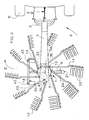
- the machine includes a swath rotor (1).
- This rotor (1) is connected to a beam (2) or to a similar support which extends more or less horizontally.
- This beam (2) is provided with a three-point coupling device (3) for attachment to the lifting rods (4) of a tractor (5).
- said rotor (1) consists of a hub (6) mounted free to rotate on a substantially vertical support axis (7).
- This hub (6) carries a ring gear (8) and a support (9) on which are fixed bearings (10) crossed by arms (11) provided with working tools (12) in the form of forks.
- a second support (13) is provided on the opposite side of the bearings (10) in order to improve their resistance.
- the rotor (1) has ten tool-carrying arms (11). Inside the volume delimited by the two supports (9 and 13), each arm (11) has a lever (14) with a roller (15) which is located in a control cam (16). This is linked to the support axis (7) by means of a key (17).
- This axis (7) is itself carried by a T-shaped frame (18), provided with three support rollers (19, 20, 21) which move on the ground during work.
- These rollers (19, 20, 21) are arranged under the rotor (1) so that their axes of rotation (22) lie substantially in two vertical planes (23 and 24) which are offset relative to the other in the direction of movement indicated by arrow D.
- These two planes (23, 24) are substantially perpendicular to the direction of movement D and are located one at the front and the other at the rear of the support pin (7).
- the three casters (19, 20, 21) are arranged in the shape of a triangle and are located in the vicinity of the path of the working tools (12).
- the support axis (7) also passes through a bore (25) of a cover (26) disposed above the aforementioned hub (6) and the crown (8). At its upper end is provided a stop ring (27) immobilized by means of a pin (28). Said cover (26) has a second bore (29) in which a drive shaft (30) is guided. This has a pinion (31) which meshes with the crown (8) of the hub (6). The other end of this shaft (30) is connected to a transmission shaft (32) which is connected, in a manner known per se, to the PTO shaft of the tractor (5).
- This axis (33) is preferably located between the two vertical planes (23 and 24) containing the axes of rotation (22) of the rollers (19, 20, 21). It can be provided slightly in front of the support axis (7).
- the cover (26) is provided with two ears (34) provided with through holes for the axis (33).
- the beam (2) also includes fixing lugs (35) with through holes for said axis (33). It can be seen in FIG. 1 that the ears (34) are arranged with a slight lateral clearance between two legs (35). The lateral positioning of the rotor (1) relative to the beam (2) is thus obtained in a simple but precise manner.
- the beam (2) is at least partially open downward and covers the upper part of the rotor (1) and the hinge pin (33). It thus ensures effective protection of these parts. It can also be seen in FIG. 1 that the articulation axis (33) is perpendicular to the beam (2) of the machine. The rotor (1) can thus pivot relative to said beam (2) to follow the unevenness of the ground.
- the rotations of the rotor (1) around the articulation axis (33) are limited using a device (36).
- the value of the pivot angle between the two extreme positions of the rotor can be of the order of 12 °. This value is sufficient for the adaptation of the rotor (1) to the unevenness that it can meet on normally maintained ground. This value can however be increased or decreased as appropriate.
- Said device (36) is provided at the rear of the support axis (7). It consists of a tongue (37) secured to the cover (26) of the rotor (1) and two tabs (38) secured to the beam (2).
- the tongue (37) is located between the legs (38) and is connected to the cover (26) of the rotor (1) by means of a yoke (39). It has an oblong hole (40) through which passes an axis (41) housed moreover in circular holes of the two legs (38). Thanks to the oblong hole (40) the tongue (37) can move with the rotor (1) relative to the legs (38). The length of this hole (40) determines the pivot angle of the rotor (1).
- the device (36) also makes it possible to block the rotor (1) relative to the beam (2). Such a blockage is useful in transport, in order to avoid swinging of the rotor (1) around the articulation axis (33) when the machine is carried by the tractor (5).
- the tongue (37) has a cylindrical hole (42) in which the pin (41) can be engaged after having aligned this hole (42) with those provided in the tabs (38).
- the two front castors (19, 20) are pivotable relative to the frame (18) around substantially vertical axes (43), while the rear caster (21) is fixed relative to the frame (18). Due to its offset from the support axis (7), it is constantly positioned behind said axis (7) regardless of the direction of movement of the machine.
- This roulette (21) thus ensures the positioning of the free assembly in rotation constituted by the support axis (7), the control cam (16) and the frame (18) as a function of the direction of movement.
- the machine is moved in direction D (figure 1) and the rotor (1) is rotated from the tractor (5) in the direction of arrow F.
- the rollers (15) of the support arms tools (11) then move in the control cam (16).
- the raceway of said rollers (15) in the cam (16) is such that, on the front part of their trajectory - seen in the direction of movement D - the tools (12) are directed downwards and pick up the lying plants on the ground and that, on the lateral part of their trajectory, they rise and deposit the plants in the form of a swath.
- the support rollers (19, 20, 21) follow the unevenness of the ground and guide the rotor (1). The latter then moves relative to the beam (2) parallel to the direction of movement D around the hinge axis (33) so that its tools (12) constantly touch the ground surface.
- the support axis (7), the control cam (16) and the rollers (19, 20, 21) are automatically oriented so that the area on which the tools (12) pick up the plants lying on the ground is in the most forward part of their trajectory, even in curves and turns.
- the two rollers (19, 20) always remain close to the pickup area. They make the tools (12) follow the unevenness of the ground by rotating the rotor transversely to the direction of movement D since the hinge pin (33) is then more or less directed in this direction D.
Landscapes
- Life Sciences & Earth Sciences (AREA)
- Environmental Sciences (AREA)
- Agricultural Machines (AREA)
- Soil Working Implements (AREA)
- Harvester Elements (AREA)
- Pharmaceuticals Containing Other Organic And Inorganic Compounds (AREA)
- Control Of Multiple Motors (AREA)
- Glass Compositions (AREA)
- Paper (AREA)
- Outside Dividers And Delivering Mechanisms For Harvesters (AREA)
Abstract
Description
- La présente invention se rapporte à une machine de fenaison comportant un rotor entraîné en rotation et muni d'outils de travail pour andainer des végétaux se trouvant sur le sol, lequel rotor est relié à une poutre ou un support analogue muni d'un dispositif d'accouplement trois points pour l'accrochage à un tracteur d'entraînement et, comporte un axe support central portant une came de commande pour lesdits outils, cet axe étant relié à un bâti avec des roulettes supports qui se déplacent sur le sol dans la position de travail et qui sont disposées de telle sorte que leurs axes de rotation se situent sensiblement dans deux plans verticaux qui sont décalés l'un par rapport à l'autre dans la direction de déplacement, la liaison entre le rotor et la poutre comprenant un axe d'articulation sensiblement horizontal et sensiblement perpendiculaire à ladite poutre et qui se situe entre les deux plans verticaux précités.
- Sur une machine de ce genre, connue dans la demande de brevet DE-A-28 33 814, le rotor est articulé par rapport à la poutre support à travers deux articulations prévues l'une au-dessus de l'autre. L'une de ces articulations comporte des axes de pivotement horizontaux qui sont liés au rotor, tandis que l'autre articulation comporte un axe de pivotement vertical lié à la poutre support. Ces articulations doivent permettre au rotor de suivre les dénivellations du sol et de s'adapter aux courbes de la trajectoire sur laquelle est déplacée la machine.
- Cette possibilité de s'adapter aux courbes de la trajectoire est cependant très limitée. Le rotor de la machine ne peut en effet se déplacer que d'un angle de faible valeur autour de l'axe de pivotement vertical si on veut lui assurer un entraînement en rotation correct à partir du tracteur. Cette machine n'est donc pas capable d'assurer un bon andainage dans toutes les conditions.
- La présente invention a notamment pour but de proposer une machine de fenaison avec un rotor d'andainage pouvant suivre les dénivellations du sol et pouvant s'adapter à toutes les courbes de la trajectoire suivie.
- A cet effet, une importante caractéristique de l'invention consiste en ce que le rotor comporte un couvercle qui est articulé sur la poutre support au moyen de l'axe d'articulation sensiblement horizontal et sensiblement perpendiculaire à ladite poutre et que l'axe support central du rotor est logé dans un alésage du couvercle de manière à pouvoir tourner durant le travail par rapport audit axe d'articulation, ensemble avec la came de commande, le bâti avec les roulettes.
- Cet agencement permet au rotor de bien suivre les dénivellations du sol et de toujours garder la zone de ramassage des outils de travail dans la partie la plus en avant de leur trajectoire et ce quelle que soit la direction de déplacement. Dans ce cas la position des organes d'entraînement du rotor demeure inchangée. Le fourrage est ainsi correctement ramassé et andainé dans toutes les courbes que doit suivre le rotor de la machine.
- En sus, des roulettes sont constamment près de la zone de ramassage afin de permettre aux outils de bien suivre les dénivellations du sol. Cela est également possible dans les courbes et les virages grâce à la possibilité qu'a le rotor de pivoter autour de l'axe d'articulation avec la poutre dans n'importe quelle position.
- D'autres caractéristiques et avantages de l'invention ressortiront des revendications et de la description ci-après d'un exemple de réalisation non limitatif de l'invention, avec référence aux dessins annexés dans lesquels :
- - la figure 1 représente une vue de dessus d'une machine selon l'invention,
- - la figure 2 représente, à plus grande échelle, une coupe à travers le rotor de la machine,
- - la figure 3 représente une vue analogue à celle de la figure 1, d'une machine dans un virage.
- Telle qu'elle est représentée sur les figures 1 à 3, la machine comporte un rotor d'andainage (1). Ce rotor (1) est relié à une poutre (2) ou à un support similaire qui s'étend plus ou moins horizontalement. Cette poutre (2) est munie d'un dispositif d'accouplement trois points (3) pour l'accrochage aux bielles de relevage (4) d'un tracteur (5).
- Comme celà ressort notamment de la figure 2, ledit rotor (1) se compose d'un moyeu (6) monté libre en rotation sur un axe support (7) sensiblement vertical. Ce moyeu (6) porte une couronne dentée (8) et un support (9) sur lequel sont fixés des paliers (10) traversés par des bras (11) munis d'outils de travail (12) en forme de fourches. Un deuxième support (13) est prévu sur le côté opposé des paliers (10) afin d'améliorer leur tenue.
- Dans l'exemple représenté sur les figures annexées le rotor (1) possède dix bras porte-outils (11). A l'intérieur du volume délimité par les deux supports (9 et 13), chaque bras (11) possède un levier (14) avec un galet (15) qui se situe dans une came de commande (16). Celle-ci est liée à l'axe support (7) au moyen d'une clavette (17). Cet axe (7) est lui-même porté par un bâti (18) en forme de T, muni de trois roulettes supports (19, 20, 21) qui se déplacent sur le sol durant le travail. Ces roulettes (19, 20, 21) sont disposées sous le rotor (1) de telle sorte que leurs axes de rotation (22) se situent sensiblement dans deux plans verticaux (23 et 24) qui sont décalés l'un par rapport à l'autre dans la direction de déplacement indiquée par le flèche D. Ces deux plans (23, 24) sont sensiblement perpendiculaires à la direction de déplacement D et se situent l'un à l'avant et l'autre à l'arrière de l'axe support (7). Les trois roulettes (19, 20, 21) sont disposées en forme de triangle et se situent au voisinage de la trajectoire des outils de travail (12).
- L'axe support (7) traverse aussi un alésage (25) d'un couvercle (26) disposé au-dessus du moyeu (6) et de la couronne (8) précités. A son extrémité supérieure est prévue une bague d'arrêt (27) immobilisée au moyen d'une goupille (28). Ledit couvercle (26) comporte un second alésage (29) dans lequel est guidé un arbre d'entraînement (30). Celui-ci possède un pignon (31) qui engrène avec la couronne (8) du moyeu (6). L'autre extrémité de cet arbre (30) est reliée à un arbre de transmission (32) qui est en liaison, d'une manière connue en soi, avec l'arbre de prise de force du tracteur (5).
- La liaison entre le rotor (1) et la poutre (2) est assurée au moyen d'un axe d'articulation (33) sensiblement horizontal. Cet axe (33) se situe de préférence entre les deux plans verticaux (23 et 24) contenant les axes de rotation (22) des roulettes (19, 20, 21). Il peut être prévu légèrement à l'avant de l'axe support (7).
- En vue de cette liaison, le couvercle (26) est pourvu de deux oreilles (34) munies de trous de passage pour l'axe (33). La poutre (2) comporte également des pattes de fixation (35) avec des trous de passage pour ledit axe (33). On voit sur la figure 1 que les oreilles (34) sont disposées avec un faible jeu latéral entre deux pattes (35). On obtient ainsi d'une manière simple mais précise le positionnement latéral du rotor (1) par rapport à la poutre (2).
- La poutre (2) est au moins partiellement ouverte vers le bas et recouvre la partie supérieure du rotor (1) et l'axe d'articulation (33). Elle assure ainsi une protection efficace de ces pièces. On voit également sur la figure 1, que l'axe d'articulation (33) est perpendiculaire à la poutre (2) de la machine. Le rotor (1) peut ainsi pivoter par rapport à ladite poutre (2) pour bien suivre les dénivellations du sol.
- Les pivotements du rotor (1) autour de l'axe d'articulation (33) sont limités à l'aide d'un dispositif (36). La valeur de l'angle de pivotement entre les deux positions extrêmes du rotor peut être de l'ordre de 12°. Cette valeur est suffisante pour l'adaptation du rotor (1) aux dénivellations qu'il peut rencontrer sur un terrain entretenu normalement. Cette valeur peut néanmoins être augmentée ou diminuée selon le cas.
- Ledit dispositif (36) est prévu à l'arrière de l'axe support (7). Il se compose d'une languette (37) solidaire du couvercle (26) du rotor (1) et de deux pattes (38) solidaires de la poutre (2). La languette (37) se situe entre les pattes (38) et est reliée au couvercle (26) du rotor (1) au moyen d'une chape (39). Elle possède un trou oblong (40) dans lequel passe un axe (41) logé par ailleurs dans des trous circulaires des deux pattes (38). Grace au trou oblong (40) la languette (37) peut se déplacer avec le rotor (1) par rapport aux pattes (38). La longueur de ce trou (40) détermine l'angle de pivotement du rotor (1). Le dispositif (36) permet aussi de bloquer le rotor (1) par rapport à la poutre (2). Un tel blocage est utile au transport, afin d'éviter des balancements du rotor (1) autour de l'axe d'articulation (33) lorsque la machine est portée par le tracteur (5). A cet effet, la languette (37) comporte un trou cylindrique (42) dans lequel peut être engagé l'axe (41) après avoir aligné ce trou (42) avec ceux prévus dans les pattes (38).
- On voit également sur la figure 2 que l'axe support (7) traverse avec un léger jeu radial l'alésage (25) du couvercle (26) du rotor (1). Cet axe (7), la came de commande (16) qui est fixée sur ledit axe et le bâti (18) des roulettes (19, 20, 21) forment un ensemble libre en rotation par rapport à l'axe d'articulation (33).
- Par ailleurs, les deux roulettes avant (19, 20) sont pivotantes par rapport au bâti (18) autour d'axes (43) sensiblement verticaux, alors que la roulette arrière (21) est fixe par rapport au bâti (18). En raison de son décalage par rapport à l'axe support (7), elle se place constamment derrière ledit axe (7) quelle que soit la direction de déplacement de la machine. Cette roulette (21) assure ainsi le positionnement de l'ensemble libre en rotation constitué par l'axe support (7), la came de commande (16) et le bâti (18) en fonction de la direction de déplacement.
- Durant le travail, la machine est déplacée dans la direction D (figure 1) et le rotor (1) est entraîné en rotation à partir du tracteur (5) dans le sens de la flèche F. Les galets (15) des bras porte-outils (11) se déplacent alors dans la came de commande (16). Le chemin de roulement desdits galets (15) dans la came (16) est tel que, sur la partie avant de leur trajectoire - vu dans la direction de déplacement D - les outils (12) sont dirigés vers le bas et ramassent les végétaux couchés sur le sol et que, sur la partie latérale de leur trajectoire, ils se lèvent et déposent les végétaux sous la forme d'un andain. Les roulettes supports (19, 20, 21) suivent les dénivellations du sol et guident le rotor (1). Celui-ci se déplace alors par rapport à la poutre (2) parallèlement à la direction de déplacement D autour de l'axe d'articulation (33) de sorte que ses outils (12) effleurent constamment la surface du sol.
- En sus, l'axe support (7), la came de commande (16) et les roulettes (19, 20, 21) s'orientent automatiquement de telle sorte que la zone sur laquelle les outils (12) ramassent les végétaux couchés sur le sol se situe dans la partie la plus en avant de leur trajectoire, même dans les courbes et les virages. Comme celà est représenté sur la figure 3, les deux roulettes (19, 20) restent toujours à proximité de la zone de ramassage. Elles font suivre aux outils (12) les dénivellations du sol en faisant pivoter le rotor transversalement à la direction de déplacement D vu que l'axe d'articulation (33) est alors plus ou moins dirigé dans cette direction D.
- Il est bien évident que l'invention n'est pas limitée au mode de réalisation tel que décrit ci-dessus et représenté sur les dessins annexés. Des modifications restent possibles, notamment du point de vue de la constitution des divers éléments ou par substitution d'équivalents techniques sans pour autant sortir du domaine de protection.
Claims (10)
Priority Applications (1)
| Application Number | Priority Date | Filing Date | Title |
|---|---|---|---|
| AT89440035T ATE78970T1 (de) | 1988-06-03 | 1989-04-27 | Heuwerbungsmaschine mit einem rechrad. |
Applications Claiming Priority (2)
| Application Number | Priority Date | Filing Date | Title |
|---|---|---|---|
| FR8807598A FR2632155B1 (fr) | 1988-06-03 | 1988-06-03 | Machine de fenaison comportant un rotor pour andainer |
| FR8807598 | 1988-06-03 |
Publications (2)
| Publication Number | Publication Date |
|---|---|
| EP0345183A1 true EP0345183A1 (fr) | 1989-12-06 |
| EP0345183B1 EP0345183B1 (fr) | 1992-08-05 |
Family
ID=9367052
Family Applications (1)
| Application Number | Title | Priority Date | Filing Date |
|---|---|---|---|
| EP89440035A Expired - Lifetime EP0345183B1 (fr) | 1988-06-03 | 1989-04-27 | Machine de fenaison comportant un rotor pour andaîner |
Country Status (7)
| Country | Link |
|---|---|
| US (1) | US4922700A (fr) |
| EP (1) | EP0345183B1 (fr) |
| AT (1) | ATE78970T1 (fr) |
| DE (1) | DE68902361T2 (fr) |
| DK (1) | DK170130B1 (fr) |
| ES (1) | ES2034734T3 (fr) |
| FR (1) | FR2632155B1 (fr) |
Cited By (3)
| Publication number | Priority date | Publication date | Assignee | Title |
|---|---|---|---|---|
| EP0590311A1 (fr) * | 1992-09-30 | 1994-04-06 | Claas Saulgau Gmbh | Rotor pour machine de fenaison en particulier pour andaîneuse |
| EP0648407A1 (fr) * | 1993-10-18 | 1995-04-19 | GREENLAND GMBH & CO. KG | Machine de fenaison |
| EP0655188A1 (fr) * | 1993-11-25 | 1995-05-31 | Kuhn S.A. | Machine de fenaison |
Families Citing this family (16)
| Publication number | Priority date | Publication date | Assignee | Title |
|---|---|---|---|---|
| FR2644320B1 (fr) * | 1989-03-20 | 1992-05-07 | Kuhn Sa | Machine agricole avec au moins un rotor pour deplacer des produits se trouvant sur le sol |
| FR2678804B1 (fr) * | 1991-07-11 | 1998-09-18 | Kuhn Sa | Machine de fenaison comportant au moins une roue rateleuse, un dispositif de protection et un deflecteur reglable. |
| FR2718324B1 (fr) * | 1994-04-12 | 1996-06-14 | Kuhn Sa | Machine de fenaison, notamment un andaineur, avec au moins un dispositif d'arrêt du rotor. |
| FR2722365B1 (fr) * | 1994-07-13 | 1996-09-20 | Kuhn Sa Societe Anonyme | Machine de fenaison, notamment une andaineuse de vegetaux a bras porte-fourches commandes |
| FR2740652B1 (fr) * | 1995-11-07 | 1998-01-30 | Kuhn Sa | Machine de fenaison comportant au moins un rotor d'andainage et permettant notamment une meilleure adaptation du rotor au relief du terrain |
| FR2746577B1 (fr) * | 1996-03-29 | 1998-05-29 | Kuhn Sa | Machine de fenaison comportant un dispositif de protection deplacable |
| FR2754136B1 (fr) * | 1996-10-03 | 1999-01-22 | Kuhn Sa | Machine de fenaison comportant un chassis compose de plusieurs troncons articules entre eux |
| FR2756137B1 (fr) * | 1996-11-26 | 1999-01-22 | Kuhn Sa | Machine de fenaison, notamment une andaineuse avec un deflecteur d'andainage reglage automatiquement dans differentes positions |
| US6272826B1 (en) | 1999-04-29 | 2001-08-14 | Sitrex S.R.L. | Method and apparatus for positioning a hay rake |
| FR2806871B1 (fr) * | 2000-04-04 | 2002-12-13 | Kuhn Sa | Machine de fenaison comportant au moins une roue rateleuse articulee sur un bras porteur |
| FR2842067B1 (fr) * | 2002-07-15 | 2005-02-04 | Kuhn Sa | Machine de fenaison avec au moins un rotor perfectionne |
| US7377093B2 (en) * | 2005-10-19 | 2008-05-27 | Cnh America Llc | Rotary crop inverter |
| NL2014732B1 (en) * | 2015-04-29 | 2017-01-18 | Forage Innovations Bv | Agricultural raking device. |
| CN105409455A (zh) * | 2015-12-21 | 2016-03-23 | 中外合资沃得重工(中国)有限公司 | 搂草臂驱动装置 |
| CN105474886A (zh) * | 2016-01-18 | 2016-04-13 | 中外合资沃得重工(中国)有限公司 | 二自由度搂草臂驱动装置 |
| GB201811406D0 (en) * | 2018-07-12 | 2018-08-29 | Agco Feucht Gmbh | Towed agricultural implement |
Citations (10)
| Publication number | Priority date | Publication date | Assignee | Title |
|---|---|---|---|---|
| FR1374202A (fr) * | 1962-11-24 | 1964-10-02 | Fella Werke Gmbh | Faneuse |
| FR1566084A (fr) * | 1967-06-01 | 1969-05-02 | ||
| DE2059269A1 (de) * | 1969-12-04 | 1971-06-09 | Poettinger Ohg Alois | Kreiselrechen |
| FR2093488A5 (fr) * | 1970-05-13 | 1972-01-28 | Bautz Gmbh Josef | |
| FR2127029A1 (fr) * | 1970-12-11 | 1972-10-13 | Lely Nv C Van Der | |
| FR2358820A1 (fr) * | 1976-07-22 | 1978-02-17 | Kuhn Sa | Machine agricole pour la fenaison |
| FR2415955A1 (fr) * | 1978-02-06 | 1979-08-31 | Kuhn Sa | Machine de fenaison permettant d'andainer en marche avant et en marche arriere |
| DE2833814A1 (de) * | 1978-08-02 | 1980-02-21 | Stoll Maschf Gmbh Wilhelm | Heuwerbungsmaschine |
| DE3628604A1 (de) * | 1986-08-22 | 1988-02-25 | Fella Werke Gmbh | Heuwerbungsmaschine |
| EP0318407A1 (fr) * | 1987-11-17 | 1989-05-31 | Kuhn S.A. | Machine de fenaison avec au moins une roue râteleuse équipée de bras porte-outils commandés |
Family Cites Families (4)
| Publication number | Priority date | Publication date | Assignee | Title |
|---|---|---|---|---|
| CH459641A (de) * | 1967-11-09 | 1968-07-15 | Bucher Guyer Ag Masch | Selbstfahrende Heuerntemaschine |
| AT314248B (de) * | 1971-04-21 | 1974-03-25 | Poettinger Ohg Alois | Lagerung der ungelenkten Nachlaufräder von landwirtschaftlichen Geräten |
| SE449417B (sv) * | 1979-05-02 | 1987-05-04 | Bucher Guyer Ag Masch | Hoberedningsmaskin samt sett att astadkomma olika onskade rorelser hos refspinnarna vid en hoberedningsmaskin |
| DE8624359U1 (de) * | 1986-09-11 | 1986-10-16 | Fella-Werke Gmbh, 8501 Feucht | Heuwerbungsmaschine |
-
1988
- 1988-06-03 FR FR8807598A patent/FR2632155B1/fr not_active Expired - Fee Related
-
1989
- 1989-04-27 EP EP89440035A patent/EP0345183B1/fr not_active Expired - Lifetime
- 1989-04-27 DE DE8989440035T patent/DE68902361T2/de not_active Expired - Fee Related
- 1989-04-27 AT AT89440035T patent/ATE78970T1/de not_active IP Right Cessation
- 1989-04-27 ES ES198989440035T patent/ES2034734T3/es not_active Expired - Lifetime
- 1989-05-26 US US07/357,278 patent/US4922700A/en not_active Expired - Lifetime
- 1989-06-02 DK DK269489A patent/DK170130B1/da not_active IP Right Cessation
Patent Citations (10)
| Publication number | Priority date | Publication date | Assignee | Title |
|---|---|---|---|---|
| FR1374202A (fr) * | 1962-11-24 | 1964-10-02 | Fella Werke Gmbh | Faneuse |
| FR1566084A (fr) * | 1967-06-01 | 1969-05-02 | ||
| DE2059269A1 (de) * | 1969-12-04 | 1971-06-09 | Poettinger Ohg Alois | Kreiselrechen |
| FR2093488A5 (fr) * | 1970-05-13 | 1972-01-28 | Bautz Gmbh Josef | |
| FR2127029A1 (fr) * | 1970-12-11 | 1972-10-13 | Lely Nv C Van Der | |
| FR2358820A1 (fr) * | 1976-07-22 | 1978-02-17 | Kuhn Sa | Machine agricole pour la fenaison |
| FR2415955A1 (fr) * | 1978-02-06 | 1979-08-31 | Kuhn Sa | Machine de fenaison permettant d'andainer en marche avant et en marche arriere |
| DE2833814A1 (de) * | 1978-08-02 | 1980-02-21 | Stoll Maschf Gmbh Wilhelm | Heuwerbungsmaschine |
| DE3628604A1 (de) * | 1986-08-22 | 1988-02-25 | Fella Werke Gmbh | Heuwerbungsmaschine |
| EP0318407A1 (fr) * | 1987-11-17 | 1989-05-31 | Kuhn S.A. | Machine de fenaison avec au moins une roue râteleuse équipée de bras porte-outils commandés |
Cited By (4)
| Publication number | Priority date | Publication date | Assignee | Title |
|---|---|---|---|---|
| EP0590311A1 (fr) * | 1992-09-30 | 1994-04-06 | Claas Saulgau Gmbh | Rotor pour machine de fenaison en particulier pour andaîneuse |
| EP0648407A1 (fr) * | 1993-10-18 | 1995-04-19 | GREENLAND GMBH & CO. KG | Machine de fenaison |
| EP0655188A1 (fr) * | 1993-11-25 | 1995-05-31 | Kuhn S.A. | Machine de fenaison |
| FR2712768A1 (fr) * | 1993-11-25 | 1995-06-02 | Kuhn Sa | Machine de fenaison pour l'andainage de fourrage, avec au moins un rotor entraîné en rotation. |
Also Published As
| Publication number | Publication date |
|---|---|
| ATE78970T1 (de) | 1992-08-15 |
| DK269489D0 (da) | 1989-06-02 |
| ES2034734T3 (es) | 1993-04-01 |
| FR2632155B1 (fr) | 1991-10-11 |
| US4922700A (en) | 1990-05-08 |
| DK269489A (da) | 1989-12-04 |
| EP0345183B1 (fr) | 1992-08-05 |
| DK170130B1 (da) | 1995-06-06 |
| DE68902361D1 (de) | 1992-09-10 |
| FR2632155A1 (fr) | 1989-12-08 |
| DE68902361T2 (de) | 1993-05-13 |
Similar Documents
| Publication | Publication Date | Title |
|---|---|---|
| EP0345183B1 (fr) | Machine de fenaison comportant un rotor pour andaîner | |
| CA1062920A (fr) | Machine de fenaison pour le fanage et l'andainage | |
| EP0337909B1 (fr) | Faucheuse à entraînement direct | |
| EP0318407B1 (fr) | Machine de fenaison avec au moins une roue râteleuse équipée de bras porte-outils commandés | |
| EP0403409B1 (fr) | Machine agricole pour l'andainage comportant des bras porte-outils repliables | |
| EP0390713B1 (fr) | Machine agricole avec au moins un rotor pour déplacer des produits se trouvant sur le sol | |
| EP0772969B1 (fr) | Machine de fenaison comportant au moins un rotor d'andainage | |
| EP1142468A1 (fr) | Machine de fenaison | |
| EP0614604B1 (fr) | Machine de fenaison | |
| FR2560737A1 (fr) | Faneuse andaineuse | |
| EP0680688B1 (fr) | Machine de fenaison, notamment un andaineur de fourrage | |
| FR2676327A1 (fr) | Andaineuse de vegetaux perfectionnee. | |
| EP0954956B1 (fr) | Machine de fenaison | |
| FR2664127A1 (fr) | Machine agricole, notamment une andaineuse de vegetaux, a largeur de travail reglable. | |
| EP0536071B1 (fr) | Machine de fenaison, notamment une faneuse de végétaux, avec au moins deux positions de travail | |
| EP0554200B1 (fr) | Machine de fenaison comportant un châssis avec des roues porteuses commandées | |
| FR2707450A1 (fr) | Machine de fenaison avec des rotors de fanage ou d'andainage munis de roues d'appui au sol. | |
| EP0654209B1 (fr) | Machine de fenaison | |
| EP1523232B1 (fr) | Machine de fenaison | |
| FR2719742A1 (fr) | Machine de fenaison, notamment une faneuse à rotors munis de bras porte-fourches avec des déflecteurs. | |
| EP0198781A1 (fr) | Machine de fenaison pour l'andainage en marche avant et en marche arrière | |
| EP0442833B1 (fr) | Machine de fenaison avec dispositif de protection perfectionné | |
| FR2553253A1 (fr) | Dispositif andaineur place a l'arriere d'une faucheuse | |
| EP0914766A1 (fr) | Machine de fenaison | |
| FR2646315A1 (fr) | Machine agricole comportant au moins un rotor muni d'outils et s'appuyant sur le sol durant le travail |
Legal Events
| Date | Code | Title | Description |
|---|---|---|---|
| PUAI | Public reference made under article 153(3) epc to a published international application that has entered the european phase |
Free format text: ORIGINAL CODE: 0009012 |
|
| AK | Designated contracting states |
Kind code of ref document: A1 Designated state(s): AT DE ES FR IT NL |
|
| 17P | Request for examination filed |
Effective date: 19900418 |
|
| 17Q | First examination report despatched |
Effective date: 19910612 |
|
| GRAA | (expected) grant |
Free format text: ORIGINAL CODE: 0009210 |
|
| ITF | It: translation for a ep patent filed | ||
| AK | Designated contracting states |
Kind code of ref document: B1 Designated state(s): AT DE ES FR IT NL |
|
| REF | Corresponds to: |
Ref document number: 78970 Country of ref document: AT Date of ref document: 19920815 Kind code of ref document: T |
|
| REF | Corresponds to: |
Ref document number: 68902361 Country of ref document: DE Date of ref document: 19920910 |
|
| REG | Reference to a national code |
Ref country code: ES Ref legal event code: FG2A Ref document number: 2034734 Country of ref document: ES Kind code of ref document: T3 |
|
| PLBE | No opposition filed within time limit |
Free format text: ORIGINAL CODE: 0009261 |
|
| STAA | Information on the status of an ep patent application or granted ep patent |
Free format text: STATUS: NO OPPOSITION FILED WITHIN TIME LIMIT |
|
| 26N | No opposition filed | ||
| PGFP | Annual fee paid to national office [announced via postgrant information from national office to epo] |
Ref country code: NL Payment date: 20030324 Year of fee payment: 15 Ref country code: AT Payment date: 20030324 Year of fee payment: 15 |
|
| PGFP | Annual fee paid to national office [announced via postgrant information from national office to epo] |
Ref country code: DE Payment date: 20030409 Year of fee payment: 15 |
|
| PGFP | Annual fee paid to national office [announced via postgrant information from national office to epo] |
Ref country code: ES Payment date: 20030411 Year of fee payment: 15 |
|
| PGFP | Annual fee paid to national office [announced via postgrant information from national office to epo] |
Ref country code: FR Payment date: 20030425 Year of fee payment: 15 |
|
| PG25 | Lapsed in a contracting state [announced via postgrant information from national office to epo] |
Ref country code: AT Free format text: LAPSE BECAUSE OF NON-PAYMENT OF DUE FEES Effective date: 20040427 |
|
| PG25 | Lapsed in a contracting state [announced via postgrant information from national office to epo] |
Ref country code: ES Free format text: LAPSE BECAUSE OF NON-PAYMENT OF DUE FEES Effective date: 20040428 |
|
| PG25 | Lapsed in a contracting state [announced via postgrant information from national office to epo] |
Ref country code: NL Free format text: LAPSE BECAUSE OF NON-PAYMENT OF DUE FEES Effective date: 20041101 |
|
| PG25 | Lapsed in a contracting state [announced via postgrant information from national office to epo] |
Ref country code: DE Free format text: LAPSE BECAUSE OF NON-PAYMENT OF DUE FEES Effective date: 20041103 |
|
| PG25 | Lapsed in a contracting state [announced via postgrant information from national office to epo] |
Ref country code: FR Free format text: LAPSE BECAUSE OF NON-PAYMENT OF DUE FEES Effective date: 20041231 |
|
| NLV4 | Nl: lapsed or anulled due to non-payment of the annual fee |
Effective date: 20041101 |
|
| REG | Reference to a national code |
Ref country code: FR Ref legal event code: ST |
|
| PG25 | Lapsed in a contracting state [announced via postgrant information from national office to epo] |
Ref country code: IT Free format text: LAPSE BECAUSE OF NON-PAYMENT OF DUE FEES Effective date: 20050427 |
|
| REG | Reference to a national code |
Ref country code: ES Ref legal event code: FD2A Effective date: 20040428 |