EP0345187A1 - Einheitssatz individueller, in mehrfach zusammengesetzten Bewegungen beweglicher Tragplatten für wagentransportierende Fahrzeuge - Google Patents
Einheitssatz individueller, in mehrfach zusammengesetzten Bewegungen beweglicher Tragplatten für wagentransportierende Fahrzeuge Download PDFInfo
- Publication number
- EP0345187A1 EP0345187A1 EP89440047A EP89440047A EP0345187A1 EP 0345187 A1 EP0345187 A1 EP 0345187A1 EP 89440047 A EP89440047 A EP 89440047A EP 89440047 A EP89440047 A EP 89440047A EP 0345187 A1 EP0345187 A1 EP 0345187A1
- Authority
- EP
- European Patent Office
- Prior art keywords
- plate
- assembly according
- connection
- screw
- unit assembly
- Prior art date
- Legal status (The legal status is an assumption and is not a legal conclusion. Google has not performed a legal analysis and makes no representation as to the accuracy of the status listed.)
- Granted
Links
- 230000007246 mechanism Effects 0.000 claims abstract description 24
- 238000013519 translation Methods 0.000 claims description 33
- 150000001875 compounds Chemical class 0.000 claims description 3
- 230000014616 translation Effects 0.000 description 28
- 238000010586 diagram Methods 0.000 description 7
- 238000006073 displacement reaction Methods 0.000 description 5
- 230000000712 assembly Effects 0.000 description 4
- 238000000429 assembly Methods 0.000 description 4
- 230000000694 effects Effects 0.000 description 2
- 238000007792 addition Methods 0.000 description 1
- 239000000969 carrier Substances 0.000 description 1
- 238000010276 construction Methods 0.000 description 1
- 230000007423 decrease Effects 0.000 description 1
- 230000002542 deteriorative effect Effects 0.000 description 1
- 239000012530 fluid Substances 0.000 description 1
- 230000002427 irreversible effect Effects 0.000 description 1
- 238000002955 isolation Methods 0.000 description 1
- 238000012986 modification Methods 0.000 description 1
- 230000004048 modification Effects 0.000 description 1
- 230000035939 shock Effects 0.000 description 1
- 238000006467 substitution reaction Methods 0.000 description 1
Images





Classifications
-
- B—PERFORMING OPERATIONS; TRANSPORTING
- B60—VEHICLES IN GENERAL
- B60P—VEHICLES ADAPTED FOR LOAD TRANSPORTATION OR TO TRANSPORT, TO CARRY, OR TO COMPRISE SPECIAL LOADS OR OBJECTS
- B60P3/00—Vehicles adapted to transport, to carry or to comprise special loads or objects
- B60P3/06—Vehicles adapted to transport, to carry or to comprise special loads or objects for carrying vehicles
- B60P3/08—Multilevel-deck construction carrying vehicles
Definitions
- the present invention relates to a unitary carrier and lifting assembly comprising at least one movable individual carrier plate for the constitution of a car carrier vehicle.
- each individual plate is capable of transverse and longitudinal movements relative to the support posts and of inclination movements relative to the horizontal from a single motor means specific to each individual plate.
- the individual carrier plates currently existing are mounted vertically movable by means of jacks, along telescopic assemblies or rectilinear profiled elements forming part of a frame, on the basis of which they bear.
- the object of the present invention is to remedy these drawbacks and to propose a unitary carrier assembly with mobile plates in multiple compound movements, characterized in that each individual plate is mounted mobile relative to its two support poles by a carrier and lifting mechanism.
- each post and each plate comprising a translation device on a single screw per post and for each post an articulation with the plate and at least one articulated oblique connection connecting the plate to the translation device.
- the general inventive idea consists in providing, for a unitary carrier assembly with two support poles, at least one plate movable relative to the poles, plate whose movements are controlled by a single external driving force through a link mechanism and a straight motor element specific to each pole on which said mechanism is mounted.
- the upper and lower end positions and inclinations are predetermined by the play of the connection mechanism associated with the straight motor element and of stops or support points.
- the general means used to implement the general inventive idea set out above include, in addition to the two support posts and at least one movable individual tray, a screw in each post, unique and specific to each post, screws serving as 'rectilinear motor element and actuated by a single independent driving force through the linkage and carrier mechanism converting the rotation of the screw in displacement movements relative to the posts and in tilting variations of the plate.
- a supporting unitary assembly 1 is produced by securing to a chassis 2 two support posts 3 and 4 which are parallel to each other and vertical or slightly inclined.
- Each support post contains at least one screw such as 5 or 6 on which is mounted a connecting and carrying mechanism and, more particularly, a translation device 7 or 8.
- the screw is unique per post and actuated by a unique driving force specific to each plate itself associated with its connecting and supporting mechanism.
- the two translation devices 7 and 8 provide the pivoting and, if necessary, pivoting-sliding support link with a movable support plate 9, of conventional shape or of particular characteristics via a pivoting axis 10 or 11 associated, where appropriate, with a sliding block.
- the movable plate 9 is capable of compound movements in inclination and displacement relative to the posts longitudinally and transversely thereto by the single control by simultaneous actuation of the screws 5 and 6 from the one and only motive force, for example a electric motor.
- This consists of a movable translation assembly 12 along the corresponding screw and carried by the latter as well as an inclined articulated connection 13 connecting the plate to the mobile assembly.
- the movable translation assembly 12 is consisting of an upper block 14 and a lower block 15 mounted on the same single screw 5 or 6 by post and by plate.
- the upper block 14 provides the pivoting connection with the plate and the lower block provides the pivoting articulation with one end of the inclined articulated connection 13 in order to produce a triangular articulated assembly with three pivoting points.
- the three points of articulation will be designated by the letters A, B, C referring respectively to the points located on the blocks 14 and 15 and on the plate at the end of the inclined connection 13.
- the blocks 14 and 15 will be of different constitution so as to allow the variation in distance between A and B and, if necessary, the variation in length of the link BC.
- the elements carried by the screws are nuts 16 in permanent or selective engagement with the screw or sliding bushings 17.
- the cages such as 18 and 19 respectively of the nuts and sockets are laterally covered with pads 20 and 21 sliding along the posts 2 and 3 in order to ensure the immobilization of the nut in rotation on itself then the guidance and the stability of the longitudinal movements.
- the upper block 14 is a nut 22 in permanent engagement with the screw.
- the cage 18 thereof is rigidly connected by a tube 23 to the cage 19 of the lower block.
- the latter is a sliding bushing 17 through which the screw passes.
- the distance AB is kept mechanically constant.
- the cage 19 of the socket 17 carries the articulation B of the inclined connection 13.
- the latter is extensible, produced for example in the form of a telescopic rod 24 or by a jack which is a functional equivalent.
- the rotation on the screw acts on the nut 22 which moves by translation up or down causing in its movements along the corresponding post the sliding bush 17 by its securing with it by the tube 23.
- the tilting movements are carried out by the extension or withdrawal of the telescopic rod 24 which can be an active rod, jack or the like, or by the play of a lower stop 25 arranged in the lower part. at the end of the plate to determine a low end of travel inclination, for example an inclination corresponding to the loading position of the vehicle.
- the weight of the loaded vehicle will automatically bring the connecting rod into the retracted position, that is to say the distance BC to its minimum value after an intermediate lifting phase during which the plate tilts down.
- the inclined connection 13 corresponds to a constant distance BC produced for example in the form of a rigid rod 26, that is to say of fixed length.
- the first variant comprises the same blocks, nut 22 and sliding bush 17, as that previously described.
- the arrangement is reversed: nut 22 in the lower position and sliding bush 17 in the upper position.
- An external connection 27 of abutment is simply established in the form, for example, of a rigid rod 28 secured at one of its ends to the cage 18 of the nut 22 by means of a connection plate 29 and guided by sliding by a tab 30 secured to the cage 19 of the sliding bushing 17 or any other equivalent means, for example a chain or a cable.
- a stop is provided, for example a bulge 31 at the end of the rod 28 or any other means.
- the distance AB is established at its maximum value by the weight of the empty or loaded plate, which is reflected by the play of the pivoting torque on the sleeve in the upper position, causing the correlative rise thereof along the screws over a distance ending at the end stop 31 of the rod 28 thus determining the inclination of the plate in its extreme low position.
- This inclination is maintained in the ascent-lifting phase up to the top end-of-travel position of the plate by the play of a high point of support, for example a stop 32, against which the end of the face comes upper plate to tilt it up, (as shown by the arrows), by the effect of the torque resulting from the upward push of the lower nut.
- a high point of support for example a stop 32, against which the end of the face comes upper plate to tilt it up, (as shown by the arrows), by the effect of the torque resulting from the upward push of the lower nut.
- the upper block is a known disengageable nut 34, for example of the type of that imagined and protected by the depositor.
- This disengageable nut 34 allows a selective grip of the nut on the screw from an external release or engagement command. Thus, by simply acting on this command, it is possible, by engagement or release, to vary the distance AB during the rotation of the screw and thus determine the inclination of the plate.
- the tilt of the low position corresponds to the loading, that is to say to the ascent of the vehicle on the platform and the tilt of the high position when the vehicle is presented during transport.
- FIGS. 8 and 9 presents identical blocks, upper 14 and lower 15, produced in the form of nuts such as those referenced 22.
- the inclined connection 13 is of variable length in the form of a telescopic rod , for example that already referenced 24 or a jack.
- BC being variable, there is an operating configuration in position of the plate, similar to that of the first variant.
- the tilting movements of the plate are made by extending or removing the telescopic rod 24 or its replacement cylinder.
- the contact with a low stop 35 begins the inclination and it is the length of extension of the connecting rod which determines the amplitude of the inclination and the final presentation of the low end of stroke of the plate corresponding to the vehicle loading position.
- the weight of the loaded vehicle will automatically bring the telescopic rod in the retracted position down, that is to say the distance BC to its minimum value after the continuation of a first lifting movement which will raise the platform of its low stop support.
- the plate will tilt as much to keep this inclination up to the high end position where a possible second stop 36 shown in dotted lines can raise the tray by tilting.
- the two blocks, upper 14 and lower 15, are either identical, produced in the form of nuts such as those already referenced 22, or different, connected by a rigid tube, for example that already referenced 23
- the inclined connection 13 each has a rod of fixed length 26.
- the nuts of identical pitch, driven by the same screw, move at a constant distance from each other, AB and BC remaining of constant length, the movements of the screw generate an overall longitudinal displacement in translation along polls.
- the tube 23 subjects the blocks 14 and 15 to remain at a constant distance from each other.
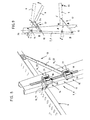
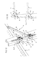
- FIGS. 14 and 15 show a variant having an additional translational mechanism 37.
- This variant proceeds from the same general inventive concept according to which the movements of the carrier plate are obtained from a single screw per post, screw driven in rotation by a single driving force.
- the blocks, upper 14 and lower 15, are produced in the form of two disengageable nuts 38 and 39.
- the articulated link 13 is a rod of fixed length such as that already referenced 26.
- the supporting link between the plate and the post is of the pivoting-sliding type by means of a slide or a shoe 40 on which a border profile 41 of the plate moves.
- the assembly is completed by a sliding mechanism 42 produced by an articulated link 43 in the form of an inclined connecting rod 44 articulated on the one hand on the plate and on the other hand on a block, for example, an upper nut 45 analogous to those already described, thus establishing an additional triangulation referenced DAF, D being the articulation with the screw and F with the plate.
- the tilting and displacement movements of the plate along the opposite bearing posts result from selective commands for engaging or disengaging the disengageable nuts 38 and 39.
- the sliding movements of the plate are directly subject to those of the screw by means of the nut 45 and the articulated connection 43 of constant length.
- disengageable nuts makes it possible to obtain and select in isolation all the possible movements of the plate: . parallel movement only when all the nuts are engaged; . pivot only when the lower nut is engaged alone; . Sliding only when the two disengageable are out of engagement.
- one of the specific applications concerns the loading and support of cars during transport on a car transporter vehicle.
- the invention offers multiple possibilities of tilting the cars in the transport position making it possible to take advantage of the free volume in the wheelbase, under the front and under the rear of the vehicles transported.
- the inclinations of the plates in extreme positions, high and low can be predetermined and identical at each stop of the screw at the end of the lifting or lowering stroke.
- a single command is sufficient to automatically place a car in its transport position taking into account the relative positions of the other cars to be loaded with a view to a maximum loading coefficient.
Landscapes
- Engineering & Computer Science (AREA)
- Health & Medical Sciences (AREA)
- Public Health (AREA)
- Transportation (AREA)
- Mechanical Engineering (AREA)
- Handcart (AREA)
- Forklifts And Lifting Vehicles (AREA)
- Automobile Manufacture Line, Endless Track Vehicle, Trailer (AREA)
- Fittings On The Vehicle Exterior For Carrying Loads, And Devices For Holding Or Mounting Articles (AREA)
- Automatic Cycles, And Cycles In General (AREA)
- Vehicle Cleaning, Maintenance, Repair, Refitting, And Outriggers (AREA)
- Automatic Assembly (AREA)
- Tyre Moulding (AREA)
- Invalid Beds And Related Equipment (AREA)
- Transmission Devices (AREA)
Priority Applications (1)
| Application Number | Priority Date | Filing Date | Title |
|---|---|---|---|
| AT89440047T ATE77589T1 (de) | 1988-05-31 | 1989-05-30 | Einheitssatz individueller, in mehrfach zusammengesetzten bewegungen beweglicher tragplatten fuer wagentransportierende fahrzeuge. |
Applications Claiming Priority (2)
| Application Number | Priority Date | Filing Date | Title |
|---|---|---|---|
| FR8807385A FR2631903B1 (fr) | 1988-05-31 | 1988-05-31 | Ensemble unitaire porteur a plateaux individuels mobiles en mouvements composes multiples pour vehicules porte-voitures |
| FR8807385 | 1988-05-31 |
Publications (2)
| Publication Number | Publication Date |
|---|---|
| EP0345187A1 true EP0345187A1 (de) | 1989-12-06 |
| EP0345187B1 EP0345187B1 (de) | 1992-06-24 |
Family
ID=9366896
Family Applications (1)
| Application Number | Title | Priority Date | Filing Date |
|---|---|---|---|
| EP89440047A Expired - Lifetime EP0345187B1 (de) | 1988-05-31 | 1989-05-30 | Einheitssatz individueller, in mehrfach zusammengesetzten Bewegungen beweglicher Tragplatten für wagentransportierende Fahrzeuge |
Country Status (8)
| Country | Link |
|---|---|
| US (1) | US5067862A (de) |
| EP (1) | EP0345187B1 (de) |
| JP (1) | JPH0238298A (de) |
| AT (1) | ATE77589T1 (de) |
| CA (1) | CA1324990C (de) |
| DE (1) | DE68901894T2 (de) |
| ES (1) | ES2033124T3 (de) |
| FR (1) | FR2631903B1 (de) |
Cited By (5)
| Publication number | Priority date | Publication date | Assignee | Title |
|---|---|---|---|---|
| FR2651732A1 (fr) * | 1989-09-12 | 1991-03-15 | Lohr Ind | Unite superieure porte-voiture pour vehicule routier. |
| CN104481184A (zh) * | 2014-12-28 | 2015-04-01 | 梁崇彦 | 一种四立柱门架式两层停车设备上台板螺杆升降驱动系统 |
| CN107215805A (zh) * | 2016-04-20 | 2017-09-29 | 梁崇彦 | 一种停车设备的多点支承直接驱动系统 |
| CN108657056A (zh) * | 2018-05-21 | 2018-10-16 | 陈为全 | 一种可承载多辆车辆的拖车结构 |
| CN112141946A (zh) * | 2020-09-30 | 2020-12-29 | 张俊杰 | 一种汽车往复举升装置 |
Families Citing this family (16)
| Publication number | Priority date | Publication date | Assignee | Title |
|---|---|---|---|---|
| US5489171A (en) * | 1994-04-15 | 1996-02-06 | Global Transport Systems, Inc. | Vehicle transporter |
| US5690453A (en) * | 1994-04-15 | 1997-11-25 | Global Transport Systems, Inc. | Method and apparatus for transporting cars |
| US5890855A (en) * | 1994-04-15 | 1999-04-06 | Claps; William R. | Method and apparatus for transporting cars |
| FR2749630B1 (fr) * | 1996-06-07 | 1998-10-09 | Lohr Ind | Dispositif de manoeuvre d'une structure porteuse a partir d'un couple de vis portant chacune un ecrou de translation |
| FR2778880B1 (fr) * | 1998-05-20 | 2000-07-21 | Lohr Ind | Structure arriere de support et de positionnement pour un vehicule de transport de voitures |
| FR2825339B1 (fr) * | 2001-05-30 | 2003-07-18 | Lohr Ind | Piece de flanc en tant que composant de carrosserie pour une unite routiere porte-vehicules motorisee ou non |
| US6572312B2 (en) * | 2001-07-20 | 2003-06-03 | Cottrell, Inc. | Power screw load retention apparatus and system |
| CA2534654C (en) | 2003-07-31 | 2013-01-08 | C. Rasmussen Martin | System and method for moving objects |
| US7025547B2 (en) * | 2004-03-29 | 2006-04-11 | Boydstun Metal Works, Inc. | Vehicle transporter with screw actuators |
| JP4741271B2 (ja) * | 2005-04-01 | 2011-08-03 | 日本郵船株式会社 | 船艙用シートおよびその設置方法 |
| US7114897B1 (en) | 2005-05-25 | 2006-10-03 | Boydstun Metal Works, Inc. | Vehicle support and retention system for a vehicle transporter |
| US7575402B2 (en) * | 2006-07-06 | 2009-08-18 | Toyota Motor Credit Corporation | Vehicle transporter with screw actuators |
| US9656590B2 (en) | 2014-05-15 | 2017-05-23 | Lippert Components, Inc. | Bed lift mounting member |
| AT518981B1 (de) * | 2016-09-13 | 2018-03-15 | Rosenbauer Int Ag | Fahrzeug, insbesondere Einsatzfahrzeug, mit einer Ladeanordnung |
| CN106812357B (zh) * | 2016-12-09 | 2019-05-31 | 合肥江瑞汽车零部件有限公司 | 一种双层停车位及具有该双层停车位的车库 |
| IT201900015935A1 (it) * | 2019-09-09 | 2019-12-09 | Rolfo Spa | Sistema di sollevamento delle pedane e veicolo per il trasporto di autoveicoli dotato di tale sistema di sollevamento delle pedane |
Citations (4)
| Publication number | Priority date | Publication date | Assignee | Title |
|---|---|---|---|---|
| GB931790A (en) * | 1961-05-18 | 1963-07-17 | Carter Engineering Company Tam | Improvements in or relating to transporter vehicles |
| FR1373916A (fr) * | 1963-08-19 | 1964-10-02 | Engin de transport d'automobiles ajustable | |
| CH593157A5 (de) * | 1974-06-13 | 1977-11-30 | Venissieux Atel | |
| EP0001364A1 (de) * | 1977-09-16 | 1979-04-04 | Lohr S.A. | Einrichtung zum Senken oder Heben der oberen Ladefläche eines Wagentransportfahrzeuges |
Family Cites Families (6)
| Publication number | Priority date | Publication date | Assignee | Title |
|---|---|---|---|---|
| US2934319A (en) * | 1956-06-20 | 1960-04-26 | Bridgeport Machines | Hydraulic jack |
| US3880457A (en) * | 1973-05-24 | 1975-04-29 | Jr Paul Jones | Trailer for transporting vehicles |
| US4081196A (en) * | 1976-10-20 | 1978-03-28 | Dandridge Jr Ernest M | Automotive vehicle transport system |
| US4369008A (en) * | 1980-10-14 | 1983-01-18 | Cooper Herbert E | Vehicle transport system |
| GB2175274A (en) * | 1985-04-19 | 1986-11-26 | Shinn I Chern | Improved screw jack |
| IT1201702B (it) * | 1986-12-15 | 1989-02-02 | Angelo Fusaro | Dispositivo per il posizionamento in quota di autovetture |
-
1988
- 1988-05-31 FR FR8807385A patent/FR2631903B1/fr not_active Expired - Fee Related
-
1989
- 1989-05-30 DE DE8989440047T patent/DE68901894T2/de not_active Expired - Lifetime
- 1989-05-30 EP EP89440047A patent/EP0345187B1/de not_active Expired - Lifetime
- 1989-05-30 ES ES198989440047T patent/ES2033124T3/es not_active Expired - Lifetime
- 1989-05-30 AT AT89440047T patent/ATE77589T1/de not_active IP Right Cessation
- 1989-05-31 CA CA000601374A patent/CA1324990C/fr not_active Expired - Fee Related
- 1989-05-31 JP JP1140211A patent/JPH0238298A/ja active Pending
- 1989-05-31 US US07/359,308 patent/US5067862A/en not_active Expired - Lifetime
Patent Citations (4)
| Publication number | Priority date | Publication date | Assignee | Title |
|---|---|---|---|---|
| GB931790A (en) * | 1961-05-18 | 1963-07-17 | Carter Engineering Company Tam | Improvements in or relating to transporter vehicles |
| FR1373916A (fr) * | 1963-08-19 | 1964-10-02 | Engin de transport d'automobiles ajustable | |
| CH593157A5 (de) * | 1974-06-13 | 1977-11-30 | Venissieux Atel | |
| EP0001364A1 (de) * | 1977-09-16 | 1979-04-04 | Lohr S.A. | Einrichtung zum Senken oder Heben der oberen Ladefläche eines Wagentransportfahrzeuges |
Cited By (7)
| Publication number | Priority date | Publication date | Assignee | Title |
|---|---|---|---|---|
| FR2651732A1 (fr) * | 1989-09-12 | 1991-03-15 | Lohr Ind | Unite superieure porte-voiture pour vehicule routier. |
| EP0418178A1 (de) * | 1989-09-12 | 1991-03-20 | Lohr Industrie | Oberfahrzeugladeeinheit für Transportfahrzeug |
| CN104481184A (zh) * | 2014-12-28 | 2015-04-01 | 梁崇彦 | 一种四立柱门架式两层停车设备上台板螺杆升降驱动系统 |
| CN107215805A (zh) * | 2016-04-20 | 2017-09-29 | 梁崇彦 | 一种停车设备的多点支承直接驱动系统 |
| CN108657056A (zh) * | 2018-05-21 | 2018-10-16 | 陈为全 | 一种可承载多辆车辆的拖车结构 |
| CN112141946A (zh) * | 2020-09-30 | 2020-12-29 | 张俊杰 | 一种汽车往复举升装置 |
| CN112141946B (zh) * | 2020-09-30 | 2022-04-19 | 江苏跃立智能科技有限公司 | 一种汽车往复举升装置 |
Also Published As
| Publication number | Publication date |
|---|---|
| DE68901894T2 (de) | 1992-12-17 |
| ATE77589T1 (de) | 1992-07-15 |
| FR2631903B1 (fr) | 1992-06-19 |
| EP0345187B1 (de) | 1992-06-24 |
| ES2033124T3 (es) | 1993-03-01 |
| US5067862A (en) | 1991-11-26 |
| FR2631903A1 (fr) | 1989-12-01 |
| JPH0238298A (ja) | 1990-02-07 |
| DE68901894D1 (de) | 1992-07-30 |
| CA1324990C (fr) | 1993-12-07 |
Similar Documents
| Publication | Publication Date | Title |
|---|---|---|
| EP0345187B1 (de) | Einheitssatz individueller, in mehrfach zusammengesetzten Bewegungen beweglicher Tragplatten für wagentransportierende Fahrzeuge | |
| EP0739286B1 (de) | Selbstlenkungsarm eines strassenfahrzeugs entlang einer leitschiene | |
| EP0233098A1 (de) | Verladevorrichtung zum Laden, insbesondere zum schnellen Transferieren von palettierten Lasten | |
| EP0755841B1 (de) | Lastförderwagen | |
| FR2516491A1 (fr) | Agencement de contrepoids pour un engin mobile, notamment une grue ou un excavateur | |
| EP1079988B1 (de) | Hintere halterungs- und positionierungsstruktur für ein fahrzeug zum transport von personenkraftwagen | |
| EP1148022A1 (de) | Rahmen für Hubgondel und Scherenhubgondel mit einem solchen Rahmen | |
| EP0905083A1 (de) | Wagen mit Hubmast, geeignet zur Montage an das Ende eines Transportfahrzeugs | |
| FR2686843A1 (fr) | Ensemble basculant-coulissant de chargement par traction a partir du sol et de transport, pour porteur routier. | |
| FR2531055A1 (fr) | Grue de levage | |
| FR2464065A1 (fr) | Dispositif pour transborder une personne handicapee moteur entre un fauteuil roulant et un vehicule automobile | |
| EP1072553A1 (de) | Zusammenklappvorrichtung eines Kranauslegers mit ineinandersetzbaren Elementen | |
| EP4157188B1 (de) | Abnehmbares elektronisches antriebssystem für ein rollendes objekt mit automatischer richtungsblockierung | |
| FR2641743A1 (fr) | Vehicule amenage pour etre equipe d'un outil interchangeable et outil destine a equiper un tel vehicule | |
| FR2689073A1 (fr) | Appareillage de manutention de charges allongées sur le toit d'un véhicule. | |
| EP0733583B1 (de) | Selbstaufstellender Kran mit seitlich klappbarem Ausleger | |
| FR3113235A1 (fr) | Système de propulsion électrique amovible pour un objet roulant - préhension et levage des roues simultanés et combinés dans la direction longitudinale | |
| FR2645521A1 (fr) | Plate-forme elevatrice mobile constituant un support pour une camera | |
| FR2544062A1 (fr) | Dispositif de transport d'un canon ou analogue | |
| FR2461678A1 (fr) | Grue mobile de levage montee sur couronne | |
| EP0761085B1 (de) | Ballenladewagen | |
| FR2490166A1 (fr) | Vehicule equipe de dispositifs de transbordement lateral de conteneurs | |
| FR2957891A1 (fr) | Bequille centrale pour moto manoeuvree electriquement s'adaptant automatiquement a l'inclinaison du sol | |
| EP0269518A1 (de) | In Form einer Hohlmuskel abwickelbares Fahrzeug | |
| LU85899A1 (fr) | Dispositif de manutention d'une goulotte de distribution d'un four a cuve |
Legal Events
| Date | Code | Title | Description |
|---|---|---|---|
| PUAI | Public reference made under article 153(3) epc to a published international application that has entered the european phase |
Free format text: ORIGINAL CODE: 0009012 |
|
| AK | Designated contracting states |
Kind code of ref document: A1 Designated state(s): AT BE CH DE ES GB IT LI LU NL |
|
| 17P | Request for examination filed |
Effective date: 19900531 |
|
| 17Q | First examination report despatched |
Effective date: 19910916 |
|
| GRAA | (expected) grant |
Free format text: ORIGINAL CODE: 0009210 |
|
| AK | Designated contracting states |
Kind code of ref document: B1 Designated state(s): AT BE CH DE ES GB IT LI LU NL |
|
| REF | Corresponds to: |
Ref document number: 77589 Country of ref document: AT Date of ref document: 19920715 Kind code of ref document: T |
|
| REF | Corresponds to: |
Ref document number: 68901894 Country of ref document: DE Date of ref document: 19920730 |
|
| ITF | It: translation for a ep patent filed | ||
| GBT | Gb: translation of ep patent filed (gb section 77(6)(a)/1977) | ||
| REG | Reference to a national code |
Ref country code: ES Ref legal event code: FG2A Ref document number: 2033124 Country of ref document: ES Kind code of ref document: T3 |
|
| PLBE | No opposition filed within time limit |
Free format text: ORIGINAL CODE: 0009261 |
|
| STAA | Information on the status of an ep patent application or granted ep patent |
Free format text: STATUS: NO OPPOSITION FILED WITHIN TIME LIMIT |
|
| 26N | No opposition filed | ||
| PGFP | Annual fee paid to national office [announced via postgrant information from national office to epo] |
Ref country code: CH Payment date: 19940414 Year of fee payment: 6 |
|
| PGFP | Annual fee paid to national office [announced via postgrant information from national office to epo] |
Ref country code: LU Payment date: 19940430 Year of fee payment: 6 |
|
| EPTA | Lu: last paid annual fee | ||
| PG25 | Lapsed in a contracting state [announced via postgrant information from national office to epo] |
Ref country code: LU Free format text: LAPSE BECAUSE OF NON-PAYMENT OF DUE FEES Effective date: 19950530 |
|
| PG25 | Lapsed in a contracting state [announced via postgrant information from national office to epo] |
Ref country code: LI Effective date: 19950531 Ref country code: CH Effective date: 19950531 |
|
| REG | Reference to a national code |
Ref country code: CH Ref legal event code: PL |
|
| REG | Reference to a national code |
Ref country code: GB Ref legal event code: IF02 |
|
| PGFP | Annual fee paid to national office [announced via postgrant information from national office to epo] |
Ref country code: ES Payment date: 20020426 Year of fee payment: 14 |
|
| PGFP | Annual fee paid to national office [announced via postgrant information from national office to epo] |
Ref country code: BE Payment date: 20020430 Year of fee payment: 14 |
|
| PGFP | Annual fee paid to national office [announced via postgrant information from national office to epo] |
Ref country code: GB Payment date: 20020501 Year of fee payment: 14 |
|
| PGFP | Annual fee paid to national office [announced via postgrant information from national office to epo] |
Ref country code: DE Payment date: 20020521 Year of fee payment: 14 |
|
| PGFP | Annual fee paid to national office [announced via postgrant information from national office to epo] |
Ref country code: AT Payment date: 20020529 Year of fee payment: 14 |
|
| PGFP | Annual fee paid to national office [announced via postgrant information from national office to epo] |
Ref country code: NL Payment date: 20020531 Year of fee payment: 14 |
|
| PG25 | Lapsed in a contracting state [announced via postgrant information from national office to epo] |
Ref country code: GB Free format text: LAPSE BECAUSE OF NON-PAYMENT OF DUE FEES Effective date: 20030530 Ref country code: AT Free format text: LAPSE BECAUSE OF NON-PAYMENT OF DUE FEES Effective date: 20030530 |
|
| PG25 | Lapsed in a contracting state [announced via postgrant information from national office to epo] |
Ref country code: ES Free format text: LAPSE BECAUSE OF NON-PAYMENT OF DUE FEES Effective date: 20030531 Ref country code: BE Free format text: LAPSE BECAUSE OF NON-PAYMENT OF DUE FEES Effective date: 20030531 |
|
| BERE | Be: lapsed |
Owner name: S.A. *LOHR INDUSTRIE Effective date: 20030531 |
|
| PG25 | Lapsed in a contracting state [announced via postgrant information from national office to epo] |
Ref country code: NL Free format text: LAPSE BECAUSE OF NON-PAYMENT OF DUE FEES Effective date: 20031201 |
|
| PG25 | Lapsed in a contracting state [announced via postgrant information from national office to epo] |
Ref country code: DE Free format text: LAPSE BECAUSE OF NON-PAYMENT OF DUE FEES Effective date: 20031202 |
|
| GBPC | Gb: european patent ceased through non-payment of renewal fee |
Effective date: 20030530 |
|
| NLV4 | Nl: lapsed or anulled due to non-payment of the annual fee |
Effective date: 20031201 |
|
| REG | Reference to a national code |
Ref country code: ES Ref legal event code: FD2A Effective date: 20030531 |
|
| PG25 | Lapsed in a contracting state [announced via postgrant information from national office to epo] |
Ref country code: IT Free format text: LAPSE BECAUSE OF NON-PAYMENT OF DUE FEES;WARNING: LAPSES OF ITALIAN PATENTS WITH EFFECTIVE DATE BEFORE 2007 MAY HAVE OCCURRED AT ANY TIME BEFORE 2007. THE CORRECT EFFECTIVE DATE MAY BE DIFFERENT FROM THE ONE RECORDED. Effective date: 20050530 |