EP0345197B1 - Mécanisme de remplissage et de décharge du réservoir d'une toilette - Google Patents
Mécanisme de remplissage et de décharge du réservoir d'une toilette Download PDFInfo
- Publication number
- EP0345197B1 EP0345197B1 EP89500051A EP89500051A EP0345197B1 EP 0345197 B1 EP0345197 B1 EP 0345197B1 EP 89500051 A EP89500051 A EP 89500051A EP 89500051 A EP89500051 A EP 89500051A EP 0345197 B1 EP0345197 B1 EP 0345197B1
- Authority
- EP
- European Patent Office
- Prior art keywords
- water
- tank
- float
- discharge
- filling
- Prior art date
- Legal status (The legal status is an assumption and is not a legal conclusion. Google has not performed a legal analysis and makes no representation as to the accuracy of the status listed.)
- Expired - Lifetime
Links
- XLYOFNOQVPJJNP-UHFFFAOYSA-N water Substances O XLYOFNOQVPJJNP-UHFFFAOYSA-N 0.000 title claims abstract description 56
- 230000007246 mechanism Effects 0.000 title claims abstract description 21
- 239000003638 chemical reducing agent Substances 0.000 claims abstract description 9
- 230000005484 gravity Effects 0.000 claims abstract description 6
- 238000007599 discharging Methods 0.000 claims description 8
- 239000007787 solid Substances 0.000 claims description 5
- 230000008878 coupling Effects 0.000 claims description 3
- 238000010168 coupling process Methods 0.000 claims description 3
- 238000005859 coupling reaction Methods 0.000 claims description 3
- 230000003247 decreasing effect Effects 0.000 claims 2
- 230000000712 assembly Effects 0.000 claims 1
- 238000000429 assembly Methods 0.000 claims 1
- 230000007423 decrease Effects 0.000 abstract description 3
- 230000000903 blocking effect Effects 0.000 abstract 1
- 238000007789 sealing Methods 0.000 description 4
- 230000001788 irregular Effects 0.000 description 2
- 239000000463 material Substances 0.000 description 2
- 239000002184 metal Substances 0.000 description 2
- 239000004033 plastic Substances 0.000 description 2
- 229920003023 plastic Polymers 0.000 description 2
- 230000002787 reinforcement Effects 0.000 description 2
- 239000004677 Nylon Substances 0.000 description 1
- 230000003466 anti-cipated effect Effects 0.000 description 1
- 210000000078 claw Anatomy 0.000 description 1
- 230000000295 complement effect Effects 0.000 description 1
- 150000001875 compounds Chemical class 0.000 description 1
- 238000011010 flushing procedure Methods 0.000 description 1
- 239000011796 hollow space material Substances 0.000 description 1
- 238000009434 installation Methods 0.000 description 1
- 229920001778 nylon Polymers 0.000 description 1
- 238000009428 plumbing Methods 0.000 description 1
- 230000007425 progressive decline Effects 0.000 description 1
- 230000001105 regulatory effect Effects 0.000 description 1
- 230000000630 rising effect Effects 0.000 description 1
Images





Classifications
-
- F—MECHANICAL ENGINEERING; LIGHTING; HEATING; WEAPONS; BLASTING
- F16—ENGINEERING ELEMENTS AND UNITS; GENERAL MEASURES FOR PRODUCING AND MAINTAINING EFFECTIVE FUNCTIONING OF MACHINES OR INSTALLATIONS; THERMAL INSULATION IN GENERAL
- F16K—VALVES; TAPS; COCKS; ACTUATING-FLOATS; DEVICES FOR VENTING OR AERATING
- F16K31/00—Actuating devices; Operating means; Releasing devices
- F16K31/12—Actuating devices; Operating means; Releasing devices actuated by fluid
- F16K31/18—Actuating devices; Operating means; Releasing devices actuated by fluid actuated by a float
- F16K31/20—Actuating devices; Operating means; Releasing devices actuated by fluid actuated by a float actuating a lift valve
- F16K31/24—Actuating devices; Operating means; Releasing devices actuated by fluid actuated by a float actuating a lift valve with a transmission with parts linked together from a single float to a single valve
- F16K31/26—Actuating devices; Operating means; Releasing devices actuated by fluid actuated by a float actuating a lift valve with a transmission with parts linked together from a single float to a single valve with the valve guided for rectilinear movement and the float attached to a pivoted arm
-
- E—FIXED CONSTRUCTIONS
- E03—WATER SUPPLY; SEWERAGE
- E03D—WATER-CLOSETS OR URINALS WITH FLUSHING DEVICES; FLUSHING VALVES THEREFOR
- E03D1/00—Water flushing devices with cisterns ; Setting up a range of flushing devices or water-closets; Combinations of several flushing devices
- E03D1/30—Valves for high or low level cisterns; Their arrangement ; Flushing mechanisms in the cistern, optionally with provisions for a pre-or a post- flushing and for cutting off the flushing mechanism in case of leakage
- E03D1/32—Arrangement of inlet valves
Definitions
- This invention relates to a simplified mechanism to fill and discharge the water tank of toilets. It has been conceived as a mechanical assembly placed inside the upper or lower tank of a toilet, and operative from the outside so that the discharge is accomplished through the combined action of a operating lever or arm and a pulling chain on the discharge float, and the action of a transverse arm having at one end an element pressing on the end part of a valve regulating the tank filling.
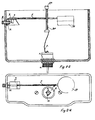
- the present Patent develops a mechanism that, in any one of its two external operating alternatives, i.e. the operating lever 2 or the operating arm 2A, drives the pulling chain 3 that lifts and causes the discharge float 4 to float, in order to allow and cause the discharge of the water contained in the tank of the toilet.
- This discharge causes a decline in the water level in the tank, which in turn forces a drop by gravity of the float 10, which through the arm 11 attached to it, acts on the splash cover 9, which projecting part 94 exerts pressure on the emerging part 71 of the valve 7 to insert it in the inner chamber 61 of the valve base 6, thus opening the inlet of water into the tank to allow a new refilling.
- the discharge float 4 stops floating and falls by gravity to close the water outlet again, thereby allowing a refilling of the tank, which takes place until the continued rising of the water level causes the floater 10 to float, and upon reaching the maximum level anticipated it stops pressing on the emerging part 71 of the valve 7, which is left free to automatically close the water intake due to the pressure exerted on it by the water incoming from the water supply system.
- a pefect sealing of the inlet mechanism is achieved by the coupling of the cone-shaped portion 72 of the valve 7 with the internal coneshape surface of the valve base 6 in front of it.
- a pressure reducer 8 reduces the water pressure at the inlet when the service pressure is excessivee, this reducer 8 being installed fixed inside the valve base 6, and through the end of said base it receives the water coming from the supply system.
- this is a mechanical assembly for filling and discharging the water tank of toilets, to carry out the flushing operation usual in toilets.
- the operating handle or knob 1 is the only external element of the mechanism, which traditionally serves to manually actuate same. It has a hollow space appropiate to hold and anchor the end 25 of the operating lever 2 or the end 21 of the operating knob 2A.
- the operating lever 2 is a four-time-bent rod, which has the irregular shape shown in Figure 5, from its upper straight and horizontal end 25, inserted and fixed within the operating handle 1, its shape is configured as follows: At the point where it departs from the operating handle 1, there occurs the first bend at 90°on a horizontal plan; then a straight and horizontal section 24 follows, after which there is the second bend at 90°from horizontal to vertical; next there is a vertical section 23, at which end the third bend, is found slightly over 90°; which is from vertical to inclined and straight, until it arrives to the fourth and last bend 22 at 90°; slightly tilted to horizontal, and finally ending in a straight and horizontal portion 20 of the rectangular section provided with holes 21 to anchor a pulling chain 3.
- the operating arm 2A is intended to directly transmit the action from the operating knob 1 to the pulling chain 3. Its upper end is threaded to receive the operating knob 1, and its lower end is flat and provided with holes to anchor the pulling chain 3. At the center, it has four protruding reinforcements which are continous and longitudinal, placed diametrically opposite each other.
- the pulling chain 3 is a traditional chain, made out of metal, plastic or nylon thread.
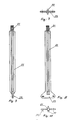
- the discharge float 4 is a floating cylinder-shaped, element consisting of a top cap and a bottom main body.
- the assembly of both parts is fixed and permanent, with water-tight sealing to maintain chamber 45 free from water.
- Centrally on the upper cap there is a projecting part 44 with an orifice to hold the pulling chain 3.
- Perimetrically on the bottom external surface of the chamber it has a continuous triangular-section flange 41 having the appropriate and matching conicity to achieve a water-tight sealing between this part 41 and the corresponding portion 51 of part No. 5, which accomodates it in the closed discharge position.
- the axle-guide 42 protrudes which lower end has a transversal through orifice 43 to place a stop pin that prevents the wole assembly from getting out of its operating position.
- the float base 5 is a cylinder-shaped part that is fixed to the tank bottom at the point of discharge. It is provided with an external thread at its bottom end to be fixed with a traditional nut. At its top end, it is provided with an external, protruding and surrounding round projection 52 to serve as a seat and fixing stop. At its top end it has a continuous and protruding triangular-section flange 51 having proper conicity to achieve a water-tight sealing between this part 51 and the corresponding part 41 of float 4 when the assembly is in the "closed draining" position. In its internal lower part it has a central, cylinder-shaped guide-box 53 which is fixed and attached to the main body through the radiuses 54. This guide-box serves to guide the vertical movement of the axle 42 of float 4.
- the valve base 6 is a tubular-shaped part with and external solid ring having a major diameter 64 from which two equal projections protrude 65, each having a concentric orifice 66. From the ring on 64, the external surface gradually decreases in diameter, forming two successive and different cones 62 and 63, until reaching the end orifice which allows the passage of water to the tank. At the water inlet end, it is provided with exterenal threading 67 to serve the double purpose of being fixed to the tank by means of a traditional nut, and receiving the coupling to the water supply system. All its inner portion is cylinder-shaped up to the point it reaches the circular channel 68, from which it gradually reduces in a conical shape until reaching the end orifice which allows the water to pass onto the tank.
- the valve 7 is a solid, cylinder-shaped part, having three different diameters, with a truncated-cone shape 72 between the two smaller diameters. Between its two larger diameters there is a circular channel 73. The end of the part having the largest diameter is cone like finish, with a rounded top 75. Throughout the external length of the part having the largest diameter, there are four or more channels placed diametrically opposite each other 74, which gradually allow the passage of water.
- the pressure reducer 8 is a plug that fits tightly and permanently in the valve base 6, having a cylinder shape with a ring protruding at the lower end that serves as a stop on the valve base 6 which accomodates it.
- Said plug has an upgoing, vertical orifice at its lower center which does not reach the top end, where it is covered or blind.
- the lower inlet of the mentioned orifice is expanded in a conical shape 81.
- Another orifice 82 is arranged horizontally and diametrically with full lengtwise passage to remain open at both ends.
- the operation or function of the pressure-reducing plug is, its name indicates, to reduce the presure of the water coming from the supply line when the service pressure is excessive.
- the splash cover 9 prevents inflowing water from splashing. It is closed on both external sides 96, on top and its front surface 95. Its internal top side presents a projection having the shape of an irregular trapezoid 94, with one of its sides 97 beveled on both surfaces, throughout its length.
- a solid longitudinal projecting block 90 having a bring longitudinal orifice 91, threaded or otherwise, intended to anchor the arm 11.
- the other end of the block 90 has a projecting arm provided with a hole 93 so that it may be assembled with the corresponding parts 65 of the valve base 6.
- the float 10 has a hollow cylindrical sealed shape both ends 101 and 105 and it consists of two complementary parts that when coupled keep the internal chamber water-tight. At its external upper lateral part, and place in a radial position, it has a reinforced tubular projection 106 and 102. Its central orifice is blind 103 and may be internally threaded or not in order to receive the axle 11.
- the arm 11 is a solid part formed by a central core having the shape of a cylindrical claw and its two ends may be threaded or not 111. Throughout the length of the unthreaded portion it has four rectangular-section reinforcements 112 placed diametrically opposite each other. This arm is fixed between the splash cover 9 and the float 10.
- the above described mechanism may be industrialized through the mechanization of a series or sufficiently hard components capable of being assembled, made out of metal or other material and other components (for example the discharge float 4 and float 10) may be lighter materials (such as plastics or alveolar compounds), forming a series of elements to be mounted in the toilet tank once this has been placed in its final location or previously at factory.
- a series or sufficiently hard components capable of being assembled, made out of metal or other material and other components may be lighter materials (such as plastics or alveolar compounds), forming a series of elements to be mounted in the toilet tank once this has been placed in its final location or previously at factory.
Landscapes
- Engineering & Computer Science (AREA)
- General Engineering & Computer Science (AREA)
- Mechanical Engineering (AREA)
- Health & Medical Sciences (AREA)
- Life Sciences & Earth Sciences (AREA)
- Hydrology & Water Resources (AREA)
- Public Health (AREA)
- Water Supply & Treatment (AREA)
- Sanitary Device For Flush Toilet (AREA)
- Bidet-Like Cleaning Device And Other Flush Toilet Accessories (AREA)
- Electrical Discharge Machining, Electrochemical Machining, And Combined Machining (AREA)
- Domestic Plumbing Installations (AREA)
Claims (6)
Priority Applications (1)
| Application Number | Priority Date | Filing Date | Title |
|---|---|---|---|
| AT89500051T ATE70872T1 (de) | 1988-04-29 | 1989-04-28 | Mechanismus zum fuellen und entleeren des wassertanks einer toilette. |
Applications Claiming Priority (2)
| Application Number | Priority Date | Filing Date | Title |
|---|---|---|---|
| ES8801343A ES2008459A6 (es) | 1988-04-29 | 1988-04-29 | Mecanismo simplificado para el llenado y vaciado del tanque de agua de inodoros. |
| ES8801343 | 1988-04-29 |
Publications (2)
| Publication Number | Publication Date |
|---|---|
| EP0345197A1 EP0345197A1 (fr) | 1989-12-06 |
| EP0345197B1 true EP0345197B1 (fr) | 1991-12-27 |
Family
ID=8256105
Family Applications (1)
| Application Number | Title | Priority Date | Filing Date |
|---|---|---|---|
| EP89500051A Expired - Lifetime EP0345197B1 (fr) | 1988-04-29 | 1989-04-28 | Mécanisme de remplissage et de décharge du réservoir d'une toilette |
Country Status (6)
| Country | Link |
|---|---|
| EP (1) | EP0345197B1 (fr) |
| AT (1) | ATE70872T1 (fr) |
| CA (1) | CA1334043C (fr) |
| DE (1) | DE68900597D1 (fr) |
| ES (1) | ES2008459A6 (fr) |
| PT (1) | PT90381B (fr) |
Family Cites Families (2)
| Publication number | Priority date | Publication date | Assignee | Title |
|---|---|---|---|---|
| CH642417A5 (it) * | 1980-10-24 | 1984-04-13 | Brevind Ets | Cassetta di scarico dell'acqua di lavaggio dei vasi w.c. negli impianti sanitari. |
| US4615056A (en) * | 1984-11-20 | 1986-10-07 | Max Rudman | Flushing cistern |
-
1988
- 1988-04-29 ES ES8801343A patent/ES2008459A6/es not_active Expired
-
1989
- 1989-04-18 CA CA000596972A patent/CA1334043C/fr not_active Expired - Fee Related
- 1989-04-27 PT PT90381A patent/PT90381B/pt active IP Right Revival
- 1989-04-28 AT AT89500051T patent/ATE70872T1/de active
- 1989-04-28 EP EP89500051A patent/EP0345197B1/fr not_active Expired - Lifetime
- 1989-04-28 DE DE8989500051T patent/DE68900597D1/de not_active Expired - Lifetime
Also Published As
| Publication number | Publication date |
|---|---|
| PT90381B (pt) | 1994-04-29 |
| DE68900597D1 (de) | 1992-02-06 |
| PT90381A (pt) | 1989-11-10 |
| CA1334043C (fr) | 1995-01-24 |
| ATE70872T1 (de) | 1992-01-15 |
| ES2008459A6 (es) | 1989-07-16 |
| EP0345197A1 (fr) | 1989-12-06 |
Similar Documents
| Publication | Publication Date | Title |
|---|---|---|
| US4651359A (en) | Dual mode flush valve assembly | |
| US4748699A (en) | Water closet limited flush volume control system | |
| US4145774A (en) | Dual flush apparatus for water closets | |
| US4406024A (en) | Flushing controller for toilet | |
| US5331690A (en) | Dual control flushing mechanism, enabling complete or partial evacuation of a toilet tank to be operated selectively | |
| US5349981A (en) | Drain valve for a flush tank | |
| US5754986A (en) | Water-saving device of water tank for flush toilet | |
| EP1233111B1 (fr) | Appareil de commande de chasse d'eau | |
| US3186007A (en) | Selectively operated stacked columns for controlling amount of discharge from flush tank | |
| US4499615A (en) | Flush and refill device | |
| US6584622B1 (en) | Method and device for timer-controlled flushing of water toilets | |
| US4937894A (en) | Dual flush toilet | |
| US3733618A (en) | Water saver attachment for toilet tank flush valve | |
| US4922556A (en) | Flushing means | |
| EP1162320B1 (fr) | Dispositif pour le rinçage d'une cuvette de toilette ou analogue | |
| US4937895A (en) | Water closet metering device | |
| EP0345197B1 (fr) | Mécanisme de remplissage et de décharge du réservoir d'une toilette | |
| US4868933A (en) | Flush control devices | |
| US4171547A (en) | Toilet-blow flush system and devices therefor | |
| US5862538A (en) | Toilet flushing device | |
| US3921226A (en) | Flush valve regulator | |
| EP1703029A1 (fr) | Dispositif d'economie quantifiee de l'eau pour les toilettes, utilisant un mecanisme de double chasse | |
| US3934276A (en) | Flushing cistern | |
| US5191662A (en) | Flush limiting mechanism | |
| US5720053A (en) | Apparatus for regulating the quantity of liquid for the flushing of toilet bowls |
Legal Events
| Date | Code | Title | Description |
|---|---|---|---|
| PUAI | Public reference made under article 153(3) epc to a published international application that has entered the european phase |
Free format text: ORIGINAL CODE: 0009012 |
|
| AK | Designated contracting states |
Kind code of ref document: A1 Designated state(s): AT BE CH DE FR GB IT LI NL SE |
|
| 17P | Request for examination filed |
Effective date: 19900319 |
|
| 17Q | First examination report despatched |
Effective date: 19901112 |
|
| GRAA | (expected) grant |
Free format text: ORIGINAL CODE: 0009210 |
|
| AK | Designated contracting states |
Kind code of ref document: B1 Designated state(s): AT BE CH DE FR GB IT LI NL SE |
|
| PG25 | Lapsed in a contracting state [announced via postgrant information from national office to epo] |
Ref country code: AT Effective date: 19911227 |
|
| REF | Corresponds to: |
Ref document number: 70872 Country of ref document: AT Date of ref document: 19920115 Kind code of ref document: T |
|
| REF | Corresponds to: |
Ref document number: 68900597 Country of ref document: DE Date of ref document: 19920206 |
|
| ITF | It: translation for a ep patent filed | ||
| ET | Fr: translation filed | ||
| PLBE | No opposition filed within time limit |
Free format text: ORIGINAL CODE: 0009261 |
|
| STAA | Information on the status of an ep patent application or granted ep patent |
Free format text: STATUS: NO OPPOSITION FILED WITHIN TIME LIMIT |
|
| 26N | No opposition filed | ||
| PGFP | Annual fee paid to national office [announced via postgrant information from national office to epo] |
Ref country code: CH Payment date: 19930405 Year of fee payment: 5 |
|
| PGFP | Annual fee paid to national office [announced via postgrant information from national office to epo] |
Ref country code: SE Payment date: 19930423 Year of fee payment: 5 |
|
| PG25 | Lapsed in a contracting state [announced via postgrant information from national office to epo] |
Ref country code: SE Effective date: 19940429 |
|
| PG25 | Lapsed in a contracting state [announced via postgrant information from national office to epo] |
Ref country code: LI Effective date: 19940430 Ref country code: CH Effective date: 19940430 |
|
| REG | Reference to a national code |
Ref country code: CH Ref legal event code: PL |
|
| EUG | Se: european patent has lapsed |
Ref document number: 89500051.1 Effective date: 19941110 |
|
| PGFP | Annual fee paid to national office [announced via postgrant information from national office to epo] |
Ref country code: NL Payment date: 19980430 Year of fee payment: 10 |
|
| PG25 | Lapsed in a contracting state [announced via postgrant information from national office to epo] |
Ref country code: NL Free format text: LAPSE BECAUSE OF NON-PAYMENT OF DUE FEES Effective date: 19991101 |
|
| NLV4 | Nl: lapsed or anulled due to non-payment of the annual fee |
Effective date: 19991101 |
|
| PGFP | Annual fee paid to national office [announced via postgrant information from national office to epo] |
Ref country code: GB Payment date: 20010426 Year of fee payment: 13 |
|
| PGFP | Annual fee paid to national office [announced via postgrant information from national office to epo] |
Ref country code: FR Payment date: 20010427 Year of fee payment: 13 |
|
| PGFP | Annual fee paid to national office [announced via postgrant information from national office to epo] |
Ref country code: BE Payment date: 20010503 Year of fee payment: 13 |
|
| PGFP | Annual fee paid to national office [announced via postgrant information from national office to epo] |
Ref country code: DE Payment date: 20010630 Year of fee payment: 13 |
|
| REG | Reference to a national code |
Ref country code: GB Ref legal event code: IF02 |
|
| PG25 | Lapsed in a contracting state [announced via postgrant information from national office to epo] |
Ref country code: GB Free format text: LAPSE BECAUSE OF NON-PAYMENT OF DUE FEES Effective date: 20020428 |
|
| PG25 | Lapsed in a contracting state [announced via postgrant information from national office to epo] |
Ref country code: BE Free format text: LAPSE BECAUSE OF NON-PAYMENT OF DUE FEES Effective date: 20020430 |
|
| PG25 | Lapsed in a contracting state [announced via postgrant information from national office to epo] |
Ref country code: DE Free format text: LAPSE BECAUSE OF NON-PAYMENT OF DUE FEES Effective date: 20021101 |
|
| GBPC | Gb: european patent ceased through non-payment of renewal fee |
Effective date: 20020428 |
|
| PG25 | Lapsed in a contracting state [announced via postgrant information from national office to epo] |
Ref country code: FR Free format text: LAPSE BECAUSE OF NON-PAYMENT OF DUE FEES Effective date: 20021231 |
|
| REG | Reference to a national code |
Ref country code: FR Ref legal event code: ST |
|
| PG25 | Lapsed in a contracting state [announced via postgrant information from national office to epo] |
Ref country code: IT Free format text: LAPSE BECAUSE OF NON-PAYMENT OF DUE FEES;WARNING: LAPSES OF ITALIAN PATENTS WITH EFFECTIVE DATE BEFORE 2007 MAY HAVE OCCURRED AT ANY TIME BEFORE 2007. THE CORRECT EFFECTIVE DATE MAY BE DIFFERENT FROM THE ONE RECORDED. Effective date: 20050428 |