EP0345200B1 - Refroidissement d'une paroi interne d'un dispositif de post-combustion - Google Patents
Refroidissement d'une paroi interne d'un dispositif de post-combustion Download PDFInfo
- Publication number
- EP0345200B1 EP0345200B1 EP89630082A EP89630082A EP0345200B1 EP 0345200 B1 EP0345200 B1 EP 0345200B1 EP 89630082 A EP89630082 A EP 89630082A EP 89630082 A EP89630082 A EP 89630082A EP 0345200 B1 EP0345200 B1 EP 0345200B1
- Authority
- EP
- European Patent Office
- Prior art keywords
- cooling air
- liner
- air holes
- holes
- augmentor
- Prior art date
- Legal status (The legal status is an assumption and is not a legal conclusion. Google has not performed a legal analysis and makes no representation as to the accuracy of the status listed.)
- Expired - Lifetime
Links
- 238000001816 cooling Methods 0.000 title claims description 60
- 238000011144 upstream manufacturing Methods 0.000 claims description 12
- 239000002184 metal Substances 0.000 claims description 6
- 210000003734 kidney Anatomy 0.000 claims description 4
- 239000007789 gas Substances 0.000 description 24
- 238000012360 testing method Methods 0.000 description 4
- 238000002485 combustion reaction Methods 0.000 description 2
- 230000001419 dependent effect Effects 0.000 description 2
- 238000007599 discharging Methods 0.000 description 2
- 238000002845 discoloration Methods 0.000 description 2
- 230000009977 dual effect Effects 0.000 description 2
- 230000000694 effects Effects 0.000 description 2
- 238000004519 manufacturing process Methods 0.000 description 2
- 238000000034 method Methods 0.000 description 2
- 238000010521 absorption reaction Methods 0.000 description 1
- 230000002411 adverse Effects 0.000 description 1
- 238000005452 bending Methods 0.000 description 1
- 238000007664 blowing Methods 0.000 description 1
- 238000010276 construction Methods 0.000 description 1
- 239000002826 coolant Substances 0.000 description 1
- 230000001627 detrimental effect Effects 0.000 description 1
- 238000005516 engineering process Methods 0.000 description 1
- 239000002245 particle Substances 0.000 description 1
- 230000000149 penetrating effect Effects 0.000 description 1
- 230000035515 penetration Effects 0.000 description 1
- 238000000926 separation method Methods 0.000 description 1
- 238000010008 shearing Methods 0.000 description 1
Images

Classifications
-
- F—MECHANICAL ENGINEERING; LIGHTING; HEATING; WEAPONS; BLASTING
- F02—COMBUSTION ENGINES; HOT-GAS OR COMBUSTION-PRODUCT ENGINE PLANTS
- F02K—JET-PROPULSION PLANTS
- F02K1/00—Plants characterised by the form or arrangement of the jet pipe or nozzle; Jet pipes or nozzles peculiar thereto
- F02K1/78—Other construction of jet pipes
- F02K1/82—Jet pipe walls, e.g. liners
-
- F—MECHANICAL ENGINEERING; LIGHTING; HEATING; WEAPONS; BLASTING
- F02—COMBUSTION ENGINES; HOT-GAS OR COMBUSTION-PRODUCT ENGINE PLANTS
- F02K—JET-PROPULSION PLANTS
- F02K1/00—Plants characterised by the form or arrangement of the jet pipe or nozzle; Jet pipes or nozzles peculiar thereto
- F02K1/78—Other construction of jet pipes
- F02K1/82—Jet pipe walls, e.g. liners
- F02K1/822—Heat insulating structures or liners, cooling arrangements, e.g. post combustion liners; Infrared radiation suppressors
-
- Y—GENERAL TAGGING OF NEW TECHNOLOGICAL DEVELOPMENTS; GENERAL TAGGING OF CROSS-SECTIONAL TECHNOLOGIES SPANNING OVER SEVERAL SECTIONS OF THE IPC; TECHNICAL SUBJECTS COVERED BY FORMER USPC CROSS-REFERENCE ART COLLECTIONS [XRACs] AND DIGESTS
- Y02—TECHNOLOGIES OR APPLICATIONS FOR MITIGATION OR ADAPTATION AGAINST CLIMATE CHANGE
- Y02T—CLIMATE CHANGE MITIGATION TECHNOLOGIES RELATED TO TRANSPORTATION
- Y02T50/00—Aeronautics or air transport
- Y02T50/60—Efficient propulsion technologies, e.g. for aircraft
Definitions
- This invention relates to liners for gas turbine engine augmentors and particularly to the cooling thereof.
- augmentor liners are fabricated from sheet metal and are formed in a corrugated or sinusoidally-shaped cylinder or conelike element so as to fall within structural and weight constraints.
- the liner is supported but spaced to the augmentor's cylindrically- shaped casing and defines an annular passageway therewith that conducts a portion of cooling air typically supplied from the compressor to openings formed in the liner and a portion that is ultimately discharged at the engine's exhaust nozzle.
- An augmentor of that type and as defined in the precharacterizing portion of in dependent claim 1 is disclosed in US-A-4,696,431.
- some perforations in the liner serve to reduce or prevent screeching, extremely high sound pressure levels created by the adjacent combustion.
- a portion of the air is used to cool the exhaust nozzle and the remaining portion is used to cool the liner itself.
- the porosity of the liner is preselected to achieve the proper liner cooling and screech dampening effects and the amount of air that is available for these purposes is predetermined. Hence, the designer of the liner must design the liner staying within these operating constraints.
- the objective that a designer has is to maintain the cooling and screech dampening requirements during the engine's operating mission without incurring any more penalty than is necessary.
- the sheet metal is relatively thin and is sinusoidally shaped, difficulty has been encountered because the jets of cooling air flowing through holes in the liner tend to penetrate into the gas path rather than lie flat over the surface of the liner. Ideally, the designer attempts to impose a film of cool air adjacent the liner surface and maintain the film uniformly around the liner in a circumferential and an axial direction. Less than ideal cooling results if the cooling air is allowed to directly penetrate into the gas path.
- US-A-4,529,358 granted to S. S. Papell on July 16, 1985 discloses a cusp-shaped hole formed in a wall for defining a passageway which is intended to cause the air passing therethrough to form a film.
- the wall is sufficiently thick so as to present sufficient coolant passage distance to define a 3-dimensional hole.
- L/D length/diameter
- the L/D would approximate a value of 5.0, where L is the length of the hole passageway, D is effective diameter which is equal to 4A ⁇ , and ⁇ is 3.1416. This is in contrast to a relatively thin sheet metal liner where the holes are punched or laser drilled in it.
- this patent does not disclose how a cusp-shpaed hole can be used to lay a film in a sinusoidally-shaped wall that hasn't sufficient dimension to form a 3-dimensional hole, and particularly where the penetration is into a recirculation zone.
- the object of the invention is to provide an augmentor for a gas turbine engine providing improved cooling of the augmentor liner.
- an augmentor for a gas turbine engine including a generally cylindrically-shaped corrugated sheet metal liner, a stream of cooling air surrounding said liner flowing axially from a most forward end to a rearward end relative to the direction of the engine's gas path, a plurality of circumferentially spaced cooling air holes in said liner, said cooling air holes being arranged in at least two adjacent circumferentially extending rows, said cooling air holes in each of said two adjacent rows being staggered so that each cooling air hole in one of said rows lies between two adjacent cooling air holes in said next adjacent row, a portion of said cooling air flowing through said cooling air holes internally of said liner, characterized in that each of said cooling air holes is in the shape of an elongated kidney and that adjacent rows of said cooling air holes are located at the upstream end of at least one of said corrugations relative to the direction of said gas path so that the portion of said cooling air that flows through said cooling air holes internally of said liner defines a film of cooling air on the internal
- the invention is based on the discovery that improved cooling can be obtained by utilizing predefined shaped holes at specific locations in the corrugated liner and in a discrete array.
- This invention is particularly efficacious in an application for an augmentor sheet metal liner for a gas turbine engine where the amount of cooling air and the porosity of the liner is predetermined.
- the concept disclosed herein may have utility in other applications.
- the designer of the liner must achieve the optimum cooling and screech absorption with specific design constraints.
- A is the amplitude of the sinusoidal wave.
- the augmentor generally illustrated by reference numeral 10 comprises a corrugated liner 12 suitably supported at one end by attachment means 14 to casing 16.
- the linear 12 and casing 16 define an annular passageway 18 for conducting the cooling air that serves to cool the liner which is exposed to the extremely high temperature of the gas path and the exhaust nozzle generally indicated by reference numeral 20.
- the cooling air admitted into the gas path through the openings in the liner should lay a film of cooling air on the inner surface of the liner to effectively shield the liner from the hot gases of the engine.
- an array of circumferentially spaced pre-shaped holes are judiciously located on the liner to effectively lay a film of cooling air on the inner surface of the liner.
- the holes 22 are elongated in the circumferential direction and are generally cusp-shaped.
- the bulbous ends 24 serve a dual purpose, namely for stress considerations and to minimize the detrimental effect of the free stream shearing caused by the cooling air discharging into the gas stream.
- the cusp shape in this application produces no vortices by virtue of its shape.
- the elongated shape of the hole serves to introduce a flat sheet of air with no or minimal internal vortical movement.
- a circle has a constant radius of curvature and has the maximum value for that given area.
- the radius of curvature is selected so that the smallest radius of curvature is not significantly smaller than that of a circle of the same area.
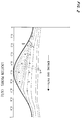
- the lines (A) represent the velocity profile of the flow adjacent the sine wave (B) of the corrugation of liner 12.
- point C where flow separation occurs, the flow reverses and recirculation occurs.
- the locus of 50% instantaneous backflow occurs as depicted by the "X" marks and 10% instantaneous backflow occurs by the "O" marks.
- the holes are located in the sine wave at a location where the flow will penetrate in the recirculation zone.
- rows should be located at a X/ ⁇ location (location on the sine wave) that is within the range of 0.3 to 0.35 for the upstream row of holes and 0.4 to 0.45 in the downstream row of holes. It is recognized that due to manufacturing constraints, the spacing between rows may have to be extended to 0.2 ⁇ which would necessitate moving the upstream row to an X/ ⁇ value of 0.15 and the downstream row to an X/ ⁇ value of 0.35.
- the hole spacings and row spacings as described and a porosity of 2% gives a ⁇ (adiabatic film cooling effectiveness) value (area averaged) of approximately 0.30 for a Blowing parameter of 1.5.
- ⁇ adiabatic film cooling effectiveness
- area averaged area averaged
- the cusp-shaped hole, oriented so that the bulbous portion 24 faces the upstream direction relative to the flow of the gas path and the judicious layout of these holes serve to locate and orient the jet of the injected cooling air in the puddle at the valley of the corrugation where it is distorted by the gases in the recirculation zone and freestream.
- the jet unfolds into a flat sheet of cold air (no vortices) and lays down completely or as near completely as possible on the inner surface of the liner. Hot entrainment into this boundary layer is minimized owing to the absence of the vortical motion.
- the pitch-to-diameter ratio in any given row has been selected as a value that equals 2.0 which is near optimum, and as was mentioned above, the row spacings provide an essentially continuous slot being encountered by the freestream air of the gas path.
- the same principles apply for the screech portion of the liner.
- the major constraint in these two portions of the liner is the porosity.
- the porosity at the cooling portion is 1.59%, while the porosity at the screech portion is 3.44%.
- the specifications for the augmentor liner construction will vary from application to application and the judicious location, the number of holes, the spacing of rows, pitch-to-diameter selection will likewise vary without departing from the particles embodied in this invention, and to this end utilizing these principles will provide a more optimum use of cooling air for an augmentor liner of a gas turbine engine.
Landscapes
- Engineering & Computer Science (AREA)
- Chemical & Material Sciences (AREA)
- Combustion & Propulsion (AREA)
- Mechanical Engineering (AREA)
- General Engineering & Computer Science (AREA)
- Turbine Rotor Nozzle Sealing (AREA)
Claims (6)
- Dispositif de postcombustion pour turbomoteur comprenant une enveloppe (12) en feuille de métal ondulée de forme globalement cylindrique, un courant d'air de refroidissement entourant ladite enveloppe (12) et s'écoulant axialement à partir d'une extrémité la plus en avant vers une extrémité arrière, par rapport à la direction d'écoulement des gaz du moteur, une pluralité de trous d'air de refroidissement (22), espacés circonférentiellement, réalisés dans ladite enveloppe (12), les trous d'air de refroidissement (22) étant disposés sur au moins deux rangées circonférentielles voisines, lesdits trous d'air de refroidissement (22) de chacune des deux rangées voisines étant disposés en quiconce de façon que chaque trou d'air de refroidissement (22) d'une des rangées s'étende entre deux trous d'air de refroidissement voisins (22) de la rangée voisine suivante, une partie de l'air de refroidissement s'écoulant au travers des trous d'air de refroidissement (22) à l'intérieur de l'enveloppe (12),
caractérisé en ce que chacun des trous d'air de refroidissement (22) a la forme d'un haricot allongé, et les rangées voisines de trous d'air de refroidissement (22) sont disposées à l'extrémité amont d'au moins une des ondulations, par rapport à la direction d'écoulement des gaz, de façon que la partie de l'air de refroidissement qui s'écoule au travers des trous d'air de refroidissement (22), à l'intérieur de l'enveloppe (12), constitue un film d'air de refroidissement sur la surface interne de ladite enveloppe (12) autour de la périphérie de celle-ci. - Dispositif de postcombustion suivant la revendication 1 caractérisé en ce que chacune des ondulations comprend deux rangées adjacentes de trous d'air de refroidissement (22) à l'extrémité amont de chacune des ondulations où le refroidissement est désiré.
- Dispositif de postcombustion suivant la revendication 1 caractérisé en ce que les ondulations ont une amplitude A et une longueur d'onde λ et un paramètre 2A/λ qui est supérieur à 0,05.
- Dispositif de postcombustion suivant la revendication 3 caractérisé en ce que le paramètre 2A/λ est voisin de 0,133, la plus en amont des deux rangées voisines est disposée à approximativement 0,3 à 0,35 λ, et la rangée voisine suivante est disposée approximativement à 0,4 à 0,45λ.
- Dispositif de postcombustion suivant la revendication 1 caractérisé en ce que le trou en forme de haricot (22) possède une surface concave faisant face à l'extrémité amont de l'enveloppe (12).
- Dispositif de postcombustion suivant la revendication 1 caractérisé en ce que l'enveloppe (12) comprend une section ou intervient le crissement, la pluralité de trous d'air de refroidissement (22) étant disposée dans cette section.
Applications Claiming Priority (2)
| Application Number | Priority Date | Filing Date | Title |
|---|---|---|---|
| US07/200,481 US4848081A (en) | 1988-05-31 | 1988-05-31 | Cooling means for augmentor liner |
| US200481 | 2002-07-19 |
Publications (2)
| Publication Number | Publication Date |
|---|---|
| EP0345200A1 EP0345200A1 (fr) | 1989-12-06 |
| EP0345200B1 true EP0345200B1 (fr) | 1993-03-31 |
Family
ID=22741907
Family Applications (1)
| Application Number | Title | Priority Date | Filing Date |
|---|---|---|---|
| EP89630082A Expired - Lifetime EP0345200B1 (fr) | 1988-05-31 | 1989-04-27 | Refroidissement d'une paroi interne d'un dispositif de post-combustion |
Country Status (5)
| Country | Link |
|---|---|
| US (1) | US4848081A (fr) |
| EP (1) | EP0345200B1 (fr) |
| JP (1) | JP2746657B2 (fr) |
| KR (1) | KR950013206B1 (fr) |
| DE (2) | DE68905671T2 (fr) |
Families Citing this family (15)
| Publication number | Priority date | Publication date | Assignee | Title |
|---|---|---|---|---|
| US4887425A (en) * | 1988-03-18 | 1989-12-19 | General Electric Company | Fuel spraybar |
| US5233828A (en) * | 1990-11-15 | 1993-08-10 | General Electric Company | Combustor liner with circumferentially angled film cooling holes |
| GB9127505D0 (en) * | 1991-03-11 | 2013-12-25 | Gen Electric | Multi-hole film cooled afterburner combustor liner |
| US5287697A (en) * | 1992-01-02 | 1994-02-22 | General Electric Company | Variable area bypass injector seal |
| US5261223A (en) * | 1992-10-07 | 1993-11-16 | General Electric Company | Multi-hole film cooled combustor liner with rectangular film restarting holes |
| FR2735561B1 (fr) * | 1995-06-14 | 1997-07-18 | Snecma | Chambre de combustion comportant une paroi annulaire multiperforee |
| US6640547B2 (en) | 2001-12-10 | 2003-11-04 | Power Systems Mfg, Llc | Effusion cooled transition duct with shaped cooling holes |
| US7966823B2 (en) * | 2006-01-06 | 2011-06-28 | General Electric Company | Exhaust dust flow splitter system |
| US8109099B2 (en) * | 2008-07-09 | 2012-02-07 | United Technologies Corporation | Flow sleeve with tabbed direct combustion liner cooling air |
| FR2948988B1 (fr) * | 2009-08-04 | 2011-12-09 | Snecma | Chambre de combustion de turbomachine comprenant des orifices d'entree d'air ameliores |
| EP2458148A1 (fr) * | 2010-11-25 | 2012-05-30 | Siemens Aktiengesellschaft | Composant de turbomachine avec surface de refroidissement |
| US10253651B2 (en) | 2012-06-14 | 2019-04-09 | United Technologies Corporation | Turbomachine flow control device |
| US10030523B2 (en) | 2015-02-13 | 2018-07-24 | United Technologies Corporation | Article having cooling passage with undulating profile |
| JP6787005B2 (ja) * | 2016-09-28 | 2020-11-18 | 株式会社Ihi | 燃焼装置用ライナ |
| CN119177901B (zh) * | 2024-11-26 | 2025-03-25 | 中国空气动力研究与发展中心低速空气动力研究所 | 一种同向流推力矢量喷管 |
Family Cites Families (18)
| Publication number | Priority date | Publication date | Assignee | Title |
|---|---|---|---|---|
| GB721209A (en) * | 1951-09-24 | 1955-01-05 | Power Jets Res & Dev Ltd | Combustion apparatus |
| US2709337A (en) * | 1952-03-28 | 1955-05-31 | United Aircraft Corp | Boundary layer control for the diffuser of a gas turbine |
| FR64436E (fr) * | 1953-06-27 | 1955-11-10 | Snecma | Perfectionnement aux dispositifs de combustion destiné notamment aux propulseurs d'aérodynes |
| US2874536A (en) * | 1954-03-18 | 1959-02-24 | Gen Electric | Cooling means for tailpipe |
| US2840989A (en) * | 1955-09-15 | 1958-07-01 | Gen Electric | End cap for combustor |
| US2974486A (en) * | 1958-03-27 | 1961-03-14 | United Aircraft Corp | Afterburner mixture and flame control baffle |
| US3137998A (en) * | 1962-10-15 | 1964-06-23 | Gen Motors Corp | Cooled rocket nozzle |
| US3420058A (en) * | 1967-01-03 | 1969-01-07 | Gen Electric | Combustor liners |
| US3485043A (en) * | 1968-02-01 | 1969-12-23 | Gen Electric | Shingled combustion liner |
| US3712062A (en) * | 1968-04-17 | 1973-01-23 | Gen Electric | Cooled augmentor liner |
| US3826088A (en) * | 1973-02-01 | 1974-07-30 | Gen Electric | Gas turbine engine augmenter cooling liner stabilizers and supports |
| US3837411A (en) * | 1973-11-21 | 1974-09-24 | Gen Electric | Diverter valve for a gas turbine with an augmenter |
| US4242871A (en) * | 1979-09-18 | 1981-01-06 | United Technologies Corporation | Louver burner liner |
| US4688310A (en) * | 1983-12-19 | 1987-08-25 | General Electric Company | Fabricated liner article and method |
| US4529358A (en) * | 1984-02-15 | 1985-07-16 | The United States Of America As Represented By The Administrator Of The National Aeronautics And Space Administration | Vortex generating flow passage design for increased film cooling effectiveness |
| US4833881A (en) * | 1984-12-17 | 1989-05-30 | General Electric Company | Gas turbine engine augmentor |
| US4696431A (en) * | 1985-11-29 | 1987-09-29 | United Technologies Corporation | Augmentor liner support band having finger positioners |
| US4718230A (en) * | 1986-11-10 | 1988-01-12 | United Technologies Corporation | Augmentor liner construction |
-
1988
- 1988-05-31 US US07/200,481 patent/US4848081A/en not_active Expired - Fee Related
-
1989
- 1989-04-27 EP EP89630082A patent/EP0345200B1/fr not_active Expired - Lifetime
- 1989-04-27 DE DE8989630082T patent/DE68905671T2/de not_active Expired - Fee Related
- 1989-04-27 DE DE198989630082T patent/DE345200T1/de active Pending
- 1989-05-30 KR KR1019890007240A patent/KR950013206B1/ko not_active Expired - Fee Related
- 1989-05-30 JP JP1137309A patent/JP2746657B2/ja not_active Expired - Fee Related
Also Published As
| Publication number | Publication date |
|---|---|
| JPH0223234A (ja) | 1990-01-25 |
| DE68905671T2 (de) | 1993-07-08 |
| US4848081A (en) | 1989-07-18 |
| EP0345200A1 (fr) | 1989-12-06 |
| KR890017446A (ko) | 1989-12-16 |
| KR950013206B1 (ko) | 1995-10-25 |
| DE345200T1 (de) | 1990-09-06 |
| DE68905671D1 (de) | 1993-05-06 |
| JP2746657B2 (ja) | 1998-05-06 |
Similar Documents
| Publication | Publication Date | Title |
|---|---|---|
| US4848081A (en) | Cooling means for augmentor liner | |
| EP0187731B1 (fr) | Chemise de chambre de combustion pour une turbine à gaz | |
| US5465572A (en) | Multi-hole film cooled afterburner cumbustor liner | |
| US7798765B2 (en) | Out-flow margin protection for a gas turbine engine | |
| US6554562B2 (en) | Combustor hot streak alignment for gas turbine engine | |
| US5233828A (en) | Combustor liner with circumferentially angled film cooling holes | |
| CA2610263C (fr) | Protecteur thermique de chambre de combustion avec refroidissement variable | |
| CA2608869C (fr) | Ensemble chemise de chambre de combustion et bouclier thermique | |
| EP3077729B1 (fr) | Interfaces d'ensemble paroi de turbine à gaz | |
| EP0492864A1 (fr) | Chambre de combustion pour turbine à gaz | |
| EP3039346B1 (fr) | Passages de dilution profilés pour chambre à combustion de turbine à gaz | |
| EP0512670A1 (fr) | Patrons de refroidissement préférentiels pour parois de chambres de combustion, percées de trous permettant le refroidissement par injection d'air | |
| EP3090208B1 (fr) | Ensemble paroi de moteur à turbine à gaz à architecture d'écoulement améliorée | |
| US20160201908A1 (en) | Vena contracta swirling dilution passages for gas turbine engine combustor | |
| MXPA05004420A (es) | Ducto de transicion enfriado por efusion con agujeros de enfriamiento configurados. | |
| EP2930428A1 (fr) | Ensemble paroi de chambre de combustion pour un moteur de turbine | |
| EP2927595A1 (fr) | Ensemble d'oeillet et procédé de conception | |
| US20060032229A1 (en) | Effusion momentum control | |
| EP0486226A1 (fr) | Chemise de chambre de combustion avec percages de reffroidissement inclinées en direction circonférentielle | |
| US11112113B2 (en) | And manufacturing process for directed impingement punched plates | |
| US20240255146A1 (en) | Dilution passages for combustor of a gas turbine engine | |
| GB2221291A (en) | Improvements in or relating to combustion chambers chambers for gas turbines engines |
Legal Events
| Date | Code | Title | Description |
|---|---|---|---|
| PUAI | Public reference made under article 153(3) epc to a published international application that has entered the european phase |
Free format text: ORIGINAL CODE: 0009012 |
|
| AK | Designated contracting states |
Kind code of ref document: A1 Designated state(s): DE FR GB SE |
|
| 17P | Request for examination filed |
Effective date: 19900509 |
|
| EL | Fr: translation of claims filed | ||
| DET | De: translation of patent claims | ||
| 17Q | First examination report despatched |
Effective date: 19911008 |
|
| GRAA | (expected) grant |
Free format text: ORIGINAL CODE: 0009210 |
|
| AK | Designated contracting states |
Kind code of ref document: B1 Designated state(s): DE FR GB SE |
|
| ET | Fr: translation filed | ||
| REF | Corresponds to: |
Ref document number: 68905671 Country of ref document: DE Date of ref document: 19930506 |
|
| PLBE | No opposition filed within time limit |
Free format text: ORIGINAL CODE: 0009261 |
|
| STAA | Information on the status of an ep patent application or granted ep patent |
Free format text: STATUS: NO OPPOSITION FILED WITHIN TIME LIMIT |
|
| 26N | No opposition filed | ||
| EAL | Se: european patent in force in sweden |
Ref document number: 89630082.9 |
|
| REG | Reference to a national code |
Ref country code: GB Ref legal event code: IF02 |
|
| PGFP | Annual fee paid to national office [announced via postgrant information from national office to epo] |
Ref country code: GB Payment date: 20060314 Year of fee payment: 18 |
|
| PGFP | Annual fee paid to national office [announced via postgrant information from national office to epo] |
Ref country code: FR Payment date: 20060403 Year of fee payment: 18 |
|
| PGFP | Annual fee paid to national office [announced via postgrant information from national office to epo] |
Ref country code: SE Payment date: 20060404 Year of fee payment: 18 |
|
| PGFP | Annual fee paid to national office [announced via postgrant information from national office to epo] |
Ref country code: DE Payment date: 20060428 Year of fee payment: 18 |
|
| GBPC | Gb: european patent ceased through non-payment of renewal fee |
Effective date: 20070427 |
|
| PG25 | Lapsed in a contracting state [announced via postgrant information from national office to epo] |
Ref country code: DE Free format text: LAPSE BECAUSE OF NON-PAYMENT OF DUE FEES Effective date: 20071101 |
|
| PG25 | Lapsed in a contracting state [announced via postgrant information from national office to epo] |
Ref country code: GB Free format text: LAPSE BECAUSE OF NON-PAYMENT OF DUE FEES Effective date: 20070427 |
|
| PG25 | Lapsed in a contracting state [announced via postgrant information from national office to epo] |
Ref country code: SE Free format text: LAPSE BECAUSE OF NON-PAYMENT OF DUE FEES Effective date: 20070428 |
|
| PG25 | Lapsed in a contracting state [announced via postgrant information from national office to epo] |
Ref country code: FR Free format text: LAPSE BECAUSE OF NON-PAYMENT OF DUE FEES Effective date: 20070430 |