EP0345276B1 - Exzentergetriebe - Google Patents
Exzentergetriebe Download PDFInfo
- Publication number
- EP0345276B1 EP0345276B1 EP88901479A EP88901479A EP0345276B1 EP 0345276 B1 EP0345276 B1 EP 0345276B1 EP 88901479 A EP88901479 A EP 88901479A EP 88901479 A EP88901479 A EP 88901479A EP 0345276 B1 EP0345276 B1 EP 0345276B1
- Authority
- EP
- European Patent Office
- Prior art keywords
- eccentric
- teeth
- gear
- gear wheel
- wheel
- Prior art date
- Legal status (The legal status is an assumption and is not a legal conclusion. Google has not performed a legal analysis and makes no representation as to the accuracy of the status listed.)
- Expired - Lifetime
Links
- 210000002105 tongue Anatomy 0.000 claims abstract 4
- 230000005484 gravity Effects 0.000 claims description 3
- 238000005096 rolling process Methods 0.000 claims 1
- 230000009467 reduction Effects 0.000 description 14
- 239000003292 glue Substances 0.000 description 6
- 238000004519 manufacturing process Methods 0.000 description 6
- 238000000034 method Methods 0.000 description 4
- 230000005540 biological transmission Effects 0.000 description 3
- 229910000831 Steel Inorganic materials 0.000 description 2
- 238000012937 correction Methods 0.000 description 2
- 238000005520 cutting process Methods 0.000 description 2
- 230000004048 modification Effects 0.000 description 2
- 238000012986 modification Methods 0.000 description 2
- 239000010959 steel Substances 0.000 description 2
- 229920003319 Araldite® Polymers 0.000 description 1
- 238000004026 adhesive bonding Methods 0.000 description 1
- 238000009826 distribution Methods 0.000 description 1
- 230000000694 effects Effects 0.000 description 1
- 230000002349 favourable effect Effects 0.000 description 1
- 230000002452 interceptive effect Effects 0.000 description 1
- 238000005259 measurement Methods 0.000 description 1
- 230000010349 pulsation Effects 0.000 description 1
Images


Classifications
-
- F—MECHANICAL ENGINEERING; LIGHTING; HEATING; WEAPONS; BLASTING
- F16—ENGINEERING ELEMENTS AND UNITS; GENERAL MEASURES FOR PRODUCING AND MAINTAINING EFFECTIVE FUNCTIONING OF MACHINES OR INSTALLATIONS; THERMAL INSULATION IN GENERAL
- F16D—COUPLINGS FOR TRANSMITTING ROTATION; CLUTCHES; BRAKES
- F16D3/00—Yielding couplings, i.e. with means permitting movement between the connected parts during the drive
- F16D3/02—Yielding couplings, i.e. with means permitting movement between the connected parts during the drive adapted to specific functions
- F16D3/04—Yielding couplings, i.e. with means permitting movement between the connected parts during the drive adapted to specific functions specially adapted to allow radial displacement, e.g. Oldham couplings
-
- F—MECHANICAL ENGINEERING; LIGHTING; HEATING; WEAPONS; BLASTING
- F16—ENGINEERING ELEMENTS AND UNITS; GENERAL MEASURES FOR PRODUCING AND MAINTAINING EFFECTIVE FUNCTIONING OF MACHINES OR INSTALLATIONS; THERMAL INSULATION IN GENERAL
- F16D—COUPLINGS FOR TRANSMITTING ROTATION; CLUTCHES; BRAKES
- F16D3/00—Yielding couplings, i.e. with means permitting movement between the connected parts during the drive
- F16D3/16—Universal joints in which flexibility is produced by means of pivots or sliding or rolling connecting parts
-
- F—MECHANICAL ENGINEERING; LIGHTING; HEATING; WEAPONS; BLASTING
- F16—ENGINEERING ELEMENTS AND UNITS; GENERAL MEASURES FOR PRODUCING AND MAINTAINING EFFECTIVE FUNCTIONING OF MACHINES OR INSTALLATIONS; THERMAL INSULATION IN GENERAL
- F16D—COUPLINGS FOR TRANSMITTING ROTATION; CLUTCHES; BRAKES
- F16D3/00—Yielding couplings, i.e. with means permitting movement between the connected parts during the drive
- F16D3/16—Universal joints in which flexibility is produced by means of pivots or sliding or rolling connecting parts
- F16D3/26—Hooke's joints or other joints with an equivalent intermediate member to which each coupling part is pivotally or slidably connected
-
- F—MECHANICAL ENGINEERING; LIGHTING; HEATING; WEAPONS; BLASTING
- F16—ENGINEERING ELEMENTS AND UNITS; GENERAL MEASURES FOR PRODUCING AND MAINTAINING EFFECTIVE FUNCTIONING OF MACHINES OR INSTALLATIONS; THERMAL INSULATION IN GENERAL
- F16H—GEARING
- F16H1/00—Toothed gearings for conveying rotary motion
- F16H1/28—Toothed gearings for conveying rotary motion with gears having orbital motion
- F16H1/32—Toothed gearings for conveying rotary motion with gears having orbital motion in which the central axis of the gearing lies inside the periphery of an orbital gear
-
- Y—GENERAL TAGGING OF NEW TECHNOLOGICAL DEVELOPMENTS; GENERAL TAGGING OF CROSS-SECTIONAL TECHNOLOGIES SPANNING OVER SEVERAL SECTIONS OF THE IPC; TECHNICAL SUBJECTS COVERED BY FORMER USPC CROSS-REFERENCE ART COLLECTIONS [XRACs] AND DIGESTS
- Y10—TECHNICAL SUBJECTS COVERED BY FORMER USPC
- Y10S—TECHNICAL SUBJECTS COVERED BY FORMER USPC CROSS-REFERENCE ART COLLECTIONS [XRACs] AND DIGESTS
- Y10S475/00—Planetary gear transmission systems or components
- Y10S475/904—Particular mathematical equation
Definitions
- the present invention relates to an excentric gear of the kind which allows high reduction, while the volume of the gear is small.
- a gear of this kind has an excentric spur gear, also known as a satellite wheel or planet wheel, which is freely journalled on an excentric stub shaft rotating together with the input shaft of the gear.
- the excentric gear wheel is in mesh with a stationary, internally toothed gear wheel and rolls round on the internal surface thereof.
- the excentric gear wheel has a circumference which is somewhat less than that of the stationary gear wheel, and as it rolls round on the inside of the stationary gear wheel it executes a slow rotation about its journal on the excentric stub shaft simultaneously as its centre of gravity rotates at a great rotational rate about the input shaft.
- the excentric wheel has a number of teeth which is less than that of the stationary gear wheel. For one revolution of the input shaft the excentric wheel has rotated in the opposite direction an angle responsive to the relationship between the number of teeth on the respective gear wheel.
- Harmonic Drive is a type of gear which has managed to avoid the problem of the teeth interfering with each other while maintaining a high gear ratio.
- the means corresponding to the moving gear wheel comprise a special thin wall ball race which is pressed on to an elliptical inner former, this ball race then receiving an externally toothed steel ring.
- This now oval-shaped ring meshes with an internally toothed rigid steel ring, which is also stationary.
- two diametrically opposed parts of the internally toothed ring are in engagement with the elliptical, elastically shaped means.
- the unmeshing teeth are kept away from the regions where they would otherwise interfere with the teeth of the stationary ring.
- Cyclo Drive is another gear structure avoiding the interference problem by not utilising teeth with involute cutting, but a kind of cycloid tooth.
- the stationary internally toothed ring has this cycloid form, and pins axially fastened to a disc on the output shaft roll off the teeth one after the other.
- the radial forces in this structure are very high, and very tight tolerances on the components are required to obtain small backlash.
- the greatest disadvantage with this gear is that a superposed pulsation on the output shaft is obtained, i.e. the gear does not give a true angular transmission.
- the "Dojan" is a variant of this type of gear.
- differential gearing is often used for achieving large reductions.
- Such gearing usually comprises a planet gear in which the sun wheel is driven at a given rotational rate and the outer, internal gear is driven in the opposite direction at approximately the same rate.
- the great disadvantage with this gearing is that it has a very low efficiency. If the rotational rate difference is very small, the unuseful power can attain almost at 100%. Since it is also desired here that the gearing shall have small backlash, tight manufacturing tolerances are required.
- WO-A-80/02677 discloses the features of the preamble of claim 1 and relates to a gear wheel transmission which is self-locking in relation to a moment of rotation acting on the output side.
- the transmission is used in a hinge fitting for motor vehicle seats having an adjustable backrest.
- Double excentric means are used as locking means to prevent the gear from rotating in its reverse direction when the backrest is loaded.
- the excentricity is reduced, a play between the sides of the gear teeth is created and the backrest can be set in any direction. Accordingly in the operative mode of the gear there is a play between the gear teeth.
- US-A-3 546 972 relates to a reduction gearing using two excentric gears which engage the teeth of a fixed internal ring gear.
- Each excentric gear is journalled on an input shaft at eccentric portions of the input shaft. There is one excentric portion for each excentric wheel.
- the teeth of the two gears are adjusted by profile shifting. There are no means by which the backlash in the gear can be adjusted. In practice backlash will inevitably occur when the direction in which the gear is loaded changes.
- the present invention has the object of achieving an excentric gearing of the kind mentioned in the introduction.
- the gear shall have great reduction, low frictional moment, low moment of inertia for the input shaft, dynamically balances operation, negligible backlash and high rigidity.
- the invention also discloses a method of graphically configurating the teeth of the stationary and excentric gear wheels in an excentric gear in accordance with the invention.
- the distinguishing features for the invention are apparent from the accompanying claims.
- the invention enables obtaining very small backlash with normal workshop tolerances between the two gear wheels of the excenter gear.
- the teeth For the one-tooth difference in the number of teeth, the teeth must have shifted profiles, as well as being stubbed and possibly having the pressure angle corrected. This correction must be made taking into account that the length of engagement between the teeth in mesh shall not be too small. A short meshing length reduces the power possible to transmit by the gear. At the same time, the clearance between the the tooth faces must not be too tight. These two factors must be weighed against each other. A condition for practically being able to use the corrected gear wheel teeth is in other words that the excentric means eliminates certain manufacturing tolerances. Tooth interference will otherwise be obtained.
- the invention permits manufacturing of a reduction gear with small backlash, but not a gear with large backlash.
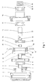
- the excentric gear includes a cylindrical housing 1 with a stationary gear wheel 2 having internal teeth, the wheel being made integrally with the housing 1. A plurality of screws 2 are intended for use in fitting the gear to the endwall of a motor.
- the excentric gear further includes: a first excentric means 4 with a first counterweight 5, a second excentric means 6 with a counterweight 7, a first ball bearing 8, an excentric gear wheel 9, also termed satellite wheel, an output shaft 10, two pivot pins 11, 12, a bush 13, a driving dog 14, a second ball bearing 15, a bearing housing 16, a third ball bearing 17, a washer 18, a shims washer 19 and a circlip 20.
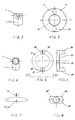
- the first excentric means 4 has a counterweight 5 in the form of a tongue projecting radially like a flange, and situated at one end of the sleeve 4 forming the mounting of the excentric means.
- the second excentric means 6 illustrated in Figure 4 has a similar configuration as the means 4 and is therefore not described in detail.
- the sleeve of the second excentric means 6 has less excentricity than that of the first excentric means 4.
- Figure 3 is a front view of the excentric gear wheel 9 with its teeth 21. This wheel has two diametrically opposing openings or "tooth gaps" 22, 23 in its side surface facing towards the driving means. The wheel is also provided on this side with an outstanding annular ring 24 accommodating the first ball bearing 8.
- the driving dog includes an annular ring part 25, on one side of which projects two diametrically opposed lugs or teeth 26, 27. These lugs are intended to slide reciprocatingly in the elongate openings 22, 23 on the excentric gear wheel. To ensure freedom from play in this motion, each lug is provided with a slit 28, clearly shown in Figure 7. There are two radial through bores 29, 30 in the annular ring, these bores being diametrically opposed and with the same angular position as the pins 26, 27 on the annular ring 25. These bores are intended to receive the pivot pins 11 and 12.
- the driving dog 10 also has bevelled parts 31 and 32 forming either side surface of the annular ring.
- the output shaft 14 associated with the driving dog is provided with a flange 33 of a radial extension allowing it to be accommodated within the annular ring part 25 of the driving dog.
- This flange is provided with two diagonally disposed bores 34, 35 for the pivot pins 11 and 12, which are a press fit in the bores.
- the output shaft is thus pivotably mounted on the pivot pins 11, 12.
- the output shaft has a central bore 36 for accommodating the bush 13 at its end provided with the flange 33.
- An annular groove 37 for the circlip 20 is arranged on the output shaft a distance away from the flange 33.
- the output part of the gear is assembled in the following way:
- the pivot pins 11, 12 are first thrust into the bores 29, 30 on the driving dog and into the bores 34, 35 on the output shaft flange.
- the bush 13, serving as a bearing for the not yet described input shaft to the excentric gear is pushed into the central bore 36 on the output shaft.
- the second ball bearing 15 is then mounted on the output shaft and subsequently thrust into the bearing housing 16.
- the third ball bearing 17 is then mounted on the output shaft from the outside of the bearing housing 16.
- the washer 18 and the shims washer 19 are then placed on the shaft, the whole assembly being locked in place by the circlip 20.
- the completed assembly illustrated in Figure 9 is thus prestressed and thus constitutes the output part of the gear.
- the input part of the gear is assembled in the following way:
- the housing 1 is screwed by the screws 3 onto the end wall of a motor 39 with an output shaft 40, illustrated schematically in Figure 10, this shaft thus constituting the input shaft of the gear.
- the first ball bearing 8 is then glued into the excentric gear wheel 9.
- a suitable glue is "Araldite” or “Locktite”.
- the exterior cylindrical part of the sleeve in the second excentric means 6 is then coated with glue and the means thrust into the inner ring of the ball bearing 8.
- Glue is then applied to the exterior cylindrical surface of the sleeve pertaining to the first excentric means 4 and this excentric means is thrust from the other side of the excentric gear wheel into the second excentric means 6, these two means 4 and 6 then assuming a mutual angular position such that the combined excentricity is minimum.
- Glue is then applied to the internal cylindrical surface of the sleeve of the excentric means 4 and the whole unit 4, 6, 8, 9 is thrust onto the output shaft 40 of the motor.
- Glue is then removed from the part of the shaft 41 projecting out over the upper surface of the first excentric means 4 and its counterweight 5.
- the excentric means 4 and 6 are then turned relative each other, causing the excentricity to increase, until there is no backlash between the teeth on the excentric wheel 2 and those of the fixed gear wheel 2, with which the excentric wheel is in mesh.
- the glue is then allowed to harden.
- Figure 10 illustrates the unit which is obtained when the input part of the gear is mounted in the described manner.
- the input and output parts are then fitted together into the unit illustrated in Figure 11.
- the bearing housing 16 is fixed to the housing 1 by the radial pins 41, set screws or the like.
- the moment of the inertia J of the system can be regarded as comprised of the moment of inertia on the output shaft, driving dog and excentric wheel, all three being reduced to the input shaft by dividing by the square of the gear ratio (i).
- This resulting moment of inertia is negligible.
- the total moment of inertia of the system is therefore solely the mass of the excentric wheel multiplied by the square of the excentricity.
- the rotation radius of the balancing mass should be kept low so that its effect on the moment of inertia of the ouput shaft will be small.
- Figure 12 illustrates certain conditions in a conventional excentric gear.
- the excentric gear wheel is freely mounted on the excentric stub shaft of the input shaft with the excentricity e.
- the pitch diameters are here 27 and 24, 6, the tooth module 0,3 and the number of teeth 90 and 82.
- the difference in the number of teeht is thus 8.
- This gives a rather small gear ratio i -10,25. It can however be seen that here already there is danger of cog inteference in an area the extremity of which is denoted by an arrow.
- Figure 13 illustrates an uncorrected excentric gear of the same type as in Figure 12, but with a tooth difference of 1 tooth.
- the gear ratio is 89:1. It will be seen that there is heavy cog interference, which is apparent from the area between 6 and 9 o'clock.
- Figure 14 shows the same gear as in Figure 13, but corrected.
- the tooth difference is one tooth.
- the gear ratio is 89:1.
- Modification by profile shifting xm -0,18 mm, stubbing and pressure angle change to 22 degrees.
- the tooth face clearance is here 0.06 mm.
- only one tooth pair in each loading direction is simultaneously in mesh.
- the teeth are slightly resilient during loading and one can therefore reckon with about 8 teeth being simultaneously in mesh in the load direction, which gives very good load distribution.
- Figure 14 shows the result of the method proposed in accordance with the invention for graphical reproduction of teeth, for a fixed internally toothed gear wheel and an excentric gear wheel in the excentric gear according to the invention.
- the fixed wheel is denoted by 2 and the excentric wheel by 9.
- the pitch circle of the excentric wheel is denoted by 55 and that of the fixed wheel by 56.
- the desired gear ratio for the excentric gear in this case 89.
- the approximate pitch diameter 56 (denoted by D s in Figure 14) is also given, and in this case it has been selected to 27 mm.
- the desired value of the tooth module reciprocal of the diametral pitch
- m 0,3.
- a first approximate value of the pitch diameter of the fixed wheel is then calculated from these three input values. These values are also used for calculating a first basic excentricity e0 which is equal to half the pitch diamter D s for the fixed wheel reduced by half the pitch diameter D r for the excentric wheel.
- the number of teeth (Z r and Z s ) is calculated for each wheel. If the number of teeth is not an integer, the pitch diameter 56 is changed and the process repeated.
- the teeth of the two gear wheels are drawn ( Figure 13) suitably using CAD, to a considerably enlagred scale, as illustrated in Figure 15 and 16 and the areas with potential cog inteference are inspected.
- the areas where the teeth are in mesh are satisfactory, but where they start to mesh it must be arranged that the faces of the respective teeth do not collide, and that the top lands of the teeth do not collide.
- a profile shift is arranged, such that the basic excentricity is changed to a new value e0 + x.m where m is the module and x is a profile shift factor.
- the top lands of the teeth are stubbed to prevent them from colliding.
- the teeth of the two gear wheels are then drawn with the teeth corrected in the way mentioned by profile shifting and stubbing.
- the result is illustrated in Figure 14. It will be understood that profile shifting does not affect the pitch circles.
- the teeth thus drawn are inspected, and a least distance between the tooth lands is decided for the teeth which are not in mesh. If this distance is not sufficent for acceptance with regard to non-correctable manufacturing tolerances, the teeth are corrected once again.
- the reference numeral 57 denotes in Figure 14 the place where the distance between the two top lands is minimum, namely 0,06 mm, although sufficently large to avoid collision.
- about 8 teeth are in mesh with each other between about 10,30 and 11,30 (clockface).
- Z r denotes the number of teeth 89 on the excentric gear wheel
- Z s the number of teeth 90 on the fixed gear wheel
- Z r the diameter of the circle the tooth top lands on the satellite gear wheel described
- Z s the diameter of the curve the tooth top lands on the fixed wheel described.
- the pitch diameters 55 and 66 cut each other at approximately 11.30, so that the pitch diameter 55 for the excentric wheel is outside the pitch diameter 57 for the fixed wheel in the area between approximaterly 10.30 and 1.30. Since the teeth have been stubbed, there are no collisions with the bottom lands within this area.
- Figure 15 illustrates a tooth pair in mesh.
- the length variation of the active face width can be determined here. By further enlargement and measurement it can be determined from tooth pair to tooth pair how well the tooth faces nestle against each other, and if it is necessary to make pressure angle corrections.
- the tooth top land clearance dimension at 57 in Figure 14, shown at an enlarged scale as f in Figure 16, is very important. A dimension which is too small gives risk for tooth interference and puts large demands on the tolerances of the components included. Too large a dimension reduces the meshing length of the teeth.
- the graphical method for producing the teeth of the two gear wheels just described is extremely convenient, compared with the very extensive calculation work which would be required in the case where each tooth were to be calculated by itself, and furthermore there would be a poor general impression of the tooth situation.
- the gear wheels are then produced using conventional tooth cutting technique.
- the embodiments of the invention described above can be modified in many ways and varied within the scope of the inventive concept.
- the counterweights can be prodivded with locking elements e.g. pins on one counterweight and grooves or openings on the other one for fixing the relative angular turn between the sleeves of the excentric means.
- Either of the excentric means 4, 6 can be provided with a balancing weight for statically balancing the imbalance moment of the excentric elements.
Landscapes
- Engineering & Computer Science (AREA)
- General Engineering & Computer Science (AREA)
- Mechanical Engineering (AREA)
- Retarders (AREA)
- Gears, Cams (AREA)
- Valve Device For Special Equipments (AREA)
- Supercharger (AREA)
- Gear Transmission (AREA)
- Transmission And Conversion Of Sensor Element Output (AREA)
Claims (4)
- Exzentergetriebe mit einer Eingangswelle (40), einer Ausgangswelle (14), einem feststehenden Zahnrad (2; 43) mit innerer Evolventenzahnung (21), einer auf der Eingangswelle montierten ersten Exzentereinrichtung (4), einer auf der ersten Exzentereinrichtung angeordneten zweiten Exzentereinrichtung (6), einem an der zweiten Exzentereinrichtung (6) drehbar gelagerten exzentrischen Zahnrad (9; 45), welches eine Evolventenzahnung aufweist, die in die Innenzahnung (21) des feststehenden Zahnrades (2, 43) eingreift, wobei das exzentrische Zahnrad (9; 45) mit verminderter Geschwindigkeit auf der Innenzahnung (21) des feststehenden Zahnrads (2; 43) abrollt, während sein Schwerpunkt mit hoher Geschwindigkeit gedreht wird, wenn die Eingangswelle mit dieser hohen Geschwindigkeit angetrieben wird, wobei die erste und zweite Exzentereinrichtung (4, 6) eine Stellvorrichtung zum Einstellen der Position des exzentrischen Zahnrads (9; 45) relativ zu dem feststehenden Zahnrad (2; 43) bildet, dadurch gekennzeichnet, daß die erste und zweite Exzentereinrichtung (4, 6) nach einer Grundeinstellung ihrer gegenseitigen Winkelposition fest miteinander verbunden sind, um (a) das Spiel in der Steuerung zu beseitigen und (b) die Eingriffslänge der miteinander im Eingriff befindlichen Zähne des feststehenden Zahnrades (2; 43) und des exzentrischen Zahnrades (9; 45) gegenüber dem Spiel zwischen zwei Zahnbergen in dem Bereich der beiden Zahnräder, wo die Zähne sich nicht im Eingriff befinden, einzustellen, daß die erste Exzentereinrichtung (4) nichtdrehbar auf der Eingangswelle (14) angeordnet ist, und daß sich die Anzahl der Zähne des exzentrischen Zahnrades (9) und die Anzahl der Zähne (21) des feststehenden Zahnrades um eins unterscheidet und durch Verschieben und Ansetzen des Profils ausgeglichen ist.
- Exzentersteuerung nach Anspruch 1, dadurch gekennzeichnet, daß die erste und zweite Exzentereinrichtung (4, 6) mit Gegengewichten (5, 7) zum dynamischen Ausgleich des Moments des Ungleichgewichts der exzentrischen Einheiten (4, 6, 9; 45) der Exzentersteuerung versehen sind.
- Exzentersteuerung nach Anspruch 1, dadurch gekennzeichnet, daß jede Exzentereinrichtung (4, 6) die Gestalt einer zylindrischen Buchse mit einer radial nach außen abstehenden Zunge (5, 7) am einen Endstück aufweist, und daß die Zungen als Ausgleichsgewichte dienen und zusammen eine Masse besitzen, die das Moment des Ungleichgewichtes des exzentrischen Zahnrades (9; 45) infolge seiner exzentrischen Anordnung auf der Eingangswelle (40) ausgleicht.
- Exzentersteuerung nach Anspruch 2, dadurch gekennzeichnet, daß die Gegengewichte (5, 7) der Exzentereinrichtungen auf entgegengesetzen Seiten des exzentrischen Zahnrades (9; 45) angeordnet sind.
Priority Applications (1)
| Application Number | Priority Date | Filing Date | Title |
|---|---|---|---|
| AT88901479T ATE94262T1 (de) | 1987-01-26 | 1988-01-26 | Exzentergetriebe. |
Applications Claiming Priority (2)
| Application Number | Priority Date | Filing Date | Title |
|---|---|---|---|
| SE8700291A SE460921B (sv) | 1987-01-26 | 1987-01-26 | Excentervaexel samt foerfarande foer grafisk framstaellning av kuggar |
| SE8700291 | 1987-06-23 |
Publications (2)
| Publication Number | Publication Date |
|---|---|
| EP0345276A1 EP0345276A1 (de) | 1989-12-13 |
| EP0345276B1 true EP0345276B1 (de) | 1993-09-08 |
Family
ID=20367295
Family Applications (1)
| Application Number | Title | Priority Date | Filing Date |
|---|---|---|---|
| EP88901479A Expired - Lifetime EP0345276B1 (de) | 1987-01-26 | 1988-01-26 | Exzentergetriebe |
Country Status (7)
| Country | Link |
|---|---|
| US (1) | US5030184A (de) |
| EP (1) | EP0345276B1 (de) |
| JP (1) | JPH02501944A (de) |
| AT (1) | ATE94262T1 (de) |
| DE (1) | DE3883971T2 (de) |
| SE (2) | SE460921B (de) |
| WO (1) | WO1988005508A1 (de) |
Cited By (1)
| Publication number | Priority date | Publication date | Assignee | Title |
|---|---|---|---|---|
| CN103206494A (zh) * | 2012-01-11 | 2013-07-17 | 株式会社捷太格特 | 减速机构以及具备该减速机构的马达旋转力传递装置 |
Families Citing this family (46)
| Publication number | Priority date | Publication date | Assignee | Title |
|---|---|---|---|---|
| SE8901303L (sv) * | 1989-04-11 | 1990-10-12 | Gustav Rennerfelt | Anordning foer dynamisk korrigering av vinkellaeget av en driven vals |
| SE464625B (sv) * | 1990-04-24 | 1991-05-27 | Gustav Rennerfelt | Lagringsanordning foer ett linjaert staelldon till vals |
| US5468193A (en) * | 1990-10-25 | 1995-11-21 | Sumitomo Heavy Industries, Ltd. | Inscribed planetary gear device having powder injection molded external gear |
| SE500254C2 (sv) * | 1991-10-09 | 1994-05-24 | Gustav Rennerfelt | Anordning för överföring av en roterande vals rotation till en axiell rörelse |
| JP2866249B2 (ja) * | 1992-04-21 | 1999-03-08 | 住友重機械工業株式会社 | 内接噛合式遊星歯車構造を採用した増減速機シリーズ |
| SE470497B (sv) * | 1992-10-22 | 1994-06-06 | Gustav Rennerfelt | Kopplingsanordning vid en excenterväxel |
| SE9302907L (sv) * | 1993-09-08 | 1995-02-20 | Gustav Rennerfelt | Excenterväxel samt förfarande för framställning av en dylik växel |
| US5470283A (en) * | 1994-01-10 | 1995-11-28 | Seidou; Yoshio | Speed reduction device |
| US5545871A (en) * | 1994-01-11 | 1996-08-13 | Micropump, Inc. | Method of making a modified elliptical gear |
| US5423628A (en) * | 1994-06-28 | 1995-06-13 | M-B-W Inc. | Winch construction for a vibratory concrete screed |
| SE9402701L (sv) * | 1994-08-12 | 1995-09-18 | Gustav Rennerfelt | Excenterväxel |
| WO1999023398A2 (en) * | 1997-11-03 | 1999-05-14 | Ker-Train Holdings Ltd. | Planetary transmission |
| SE515763C2 (sv) | 2000-02-22 | 2001-10-08 | Scandrive Control Ab | Excenterväxel |
| US6361461B1 (en) * | 2000-03-29 | 2002-03-26 | Pavo Pusic | Multiple-speed chain driving device |
| DE10018108C2 (de) * | 2000-04-12 | 2002-04-04 | Keiper Gmbh & Co | Getriebebeschlag für einen Fahrzeugsitzeinsteller |
| US7051344B2 (en) * | 2000-11-20 | 2006-05-23 | Sony Corporation | Disk tray moving device and disk recording and/or reproducing device |
| US7122926B2 (en) * | 2002-09-19 | 2006-10-17 | Delbert Tesar | Fault-tolerant rotary actuator |
| US9879760B2 (en) | 2002-11-25 | 2018-01-30 | Delbert Tesar | Rotary actuator with shortest force path configuration |
| US7081062B2 (en) * | 2002-11-25 | 2006-07-25 | Delbert Tesar | Standardized rotary actuator |
| DE10359575A1 (de) * | 2003-12-18 | 2005-07-28 | Robert Bosch Gmbh | Getriebe |
| DE102005053447B4 (de) * | 2005-11-04 | 2014-06-05 | Brose Fahrzeugteile Gmbh & Co. Kommanditgesellschaft, Coburg | Taumelgetriebe für eine Fahrzeugsitz-Verstelleinrichtung |
| JP5223863B2 (ja) * | 2007-06-11 | 2013-06-26 | トヨタ紡織株式会社 | 回動機構 |
| US8016714B2 (en) | 2008-08-19 | 2011-09-13 | Ford Global Technologies, Llc | Multiple speed transmission utilizing co-planar gear sets |
| US8180143B2 (en) * | 2008-12-23 | 2012-05-15 | General Electric Company | Method and system for estimating contact patterns |
| US8257217B2 (en) | 2009-02-03 | 2012-09-04 | Ford Global Technologies, Llc | Infinitely variable transmission with offset output shaft |
| US8187139B2 (en) | 2009-02-06 | 2012-05-29 | Ford Global Technologies, Llc | Planetary kinematic arrangement suitable for idle engine stop |
| US8113982B2 (en) | 2009-03-30 | 2012-02-14 | Ford Global Technologies, Llc | Eight speed planetary kinematic arrangement |
| IT1398940B1 (it) * | 2009-06-30 | 2013-03-28 | Caeb Internat S R L | Riduttore meccanico perfezionato |
| DE102009039648B3 (de) * | 2009-08-28 | 2011-02-24 | Keiper Gmbh & Co. Kg | Beschlag für einen Fahrzeugsitz und Fahrzeugsitz |
| KR101485863B1 (ko) * | 2012-08-17 | 2015-01-26 | 가부시키가이샤 하모닉 드라이브 시스템즈 | 3 차원 접촉 치형을 가지는 파동 기어 장치 |
| US10024392B2 (en) | 2015-08-25 | 2018-07-17 | Fisher & Company, Incorporated | Single-stage gear reduction output mechanism having a locking gear with pin receiving guide holes and anti-back drive capability for automotive seat adjuster drives |
| US9902295B2 (en) | 2015-08-25 | 2018-02-27 | Fisher & Company, Incorporated | Single-stage gear reduction output mechanism with a locking fork providing anti-back drive capability for automotive seat adjuster drives |
| US10195975B2 (en) | 2016-01-19 | 2019-02-05 | Fisher & Company, Incorporated | Gear assembly for a seat adjuster |
| US10843591B2 (en) | 2016-01-19 | 2020-11-24 | Fisher & Company, Incorporated | Gear assembly for a seat adjuster |
| US10953772B2 (en) | 2016-09-08 | 2021-03-23 | Fisher & Company, Incorporated | Open architecture power length adjuster assembly for a vehicle seat and method of manufacturing the same |
| US11273506B2 (en) | 2016-09-08 | 2022-03-15 | Fisher & Company, Incorporated | Open architecture power length adjuster assembly for a vehicle seat and method of manufacturing the same |
| US11766956B2 (en) | 2016-09-08 | 2023-09-26 | Fisher & Company, Incorporated | Open architecture power length adjuster assembly for a vehicle seat and method of manufacturing the same |
| JP6958002B2 (ja) * | 2017-06-12 | 2021-11-02 | 株式会社デンソー | 内接噛合遊星歯車機構 |
| CN109114200A (zh) * | 2018-10-25 | 2019-01-01 | 山东柳杭减速机有限公司 | 大重合度内啮合行星传动减速机 |
| CN113272172B (zh) | 2019-01-09 | 2023-06-27 | 费舍尔和同伴有限公司 | 动力座椅轨道组件 |
| US11760233B2 (en) | 2019-02-20 | 2023-09-19 | Fisher & Company, Incorporated | Ultra-compact power length adjuster with anti-back drive capability and pinion-rack output for a vehicle seat |
| US11529892B2 (en) | 2020-05-01 | 2022-12-20 | Fisher & Company, Incorporated | Gearbox for vehicle seat adjustment mechanism |
| US11485255B2 (en) | 2020-05-01 | 2022-11-01 | Fisher & Company, Incorporated | Gearbox for vehicle seat adjustment mechanism |
| JP7546498B2 (ja) * | 2021-02-16 | 2024-09-06 | 三菱電機Fa産業機器株式会社 | ハイポサイクロイド減速機構 |
| US12496937B2 (en) | 2022-10-12 | 2025-12-16 | Fisher & Company, Incorporated | Vehicle seat adjustment system with power long rails |
| US12503016B2 (en) | 2022-10-12 | 2025-12-23 | Fisher & Company, Incorporated | Vehicle seat adjustment assembly with reduced-backlash gear system |
Family Cites Families (8)
| Publication number | Priority date | Publication date | Assignee | Title |
|---|---|---|---|---|
| US1770035A (en) * | 1927-09-09 | 1930-07-08 | Heap Walter | Speed-reduction gearing |
| US3019705A (en) * | 1957-12-13 | 1962-02-06 | American Optical Corp | Coarse and fine adjustment mechanism for microscopes |
| US3037400A (en) * | 1959-01-14 | 1962-06-05 | Edward V Sundt | Differential gear reducer |
| US3424036A (en) * | 1967-01-17 | 1969-01-28 | Rex Chainbelt Inc | Speed changing device |
| GB1198737A (en) * | 1967-08-30 | 1970-07-15 | Muneharu Morozumi | Addendum Modified Involute Internal Gearing |
| DE2921588C2 (de) * | 1979-05-28 | 1982-07-01 | Privates Institut für physikalisch technische Auftragsforschung GmbH, 6107 Reinheim | Vorrichtung zum Beseitigen des Spiels in einem Zahnradgetriebe |
| US4512213A (en) * | 1981-10-30 | 1985-04-23 | Newton Alan R | Speed reducer |
| US4402544A (en) * | 1982-01-07 | 1983-09-06 | Artim Rufus R | Folding canopy for truck and trailer loads |
-
1987
- 1987-01-26 SE SE8700291A patent/SE460921B/sv not_active IP Right Cessation
- 1987-04-01 SE SE8701362A patent/SE456364B/sv not_active IP Right Cessation
-
1988
- 1988-01-26 JP JP63501520A patent/JPH02501944A/ja active Pending
- 1988-01-26 DE DE88901479T patent/DE3883971T2/de not_active Expired - Fee Related
- 1988-01-26 US US07/392,526 patent/US5030184A/en not_active Expired - Fee Related
- 1988-01-26 EP EP88901479A patent/EP0345276B1/de not_active Expired - Lifetime
- 1988-01-26 WO PCT/SE1988/000027 patent/WO1988005508A1/en not_active Ceased
- 1988-01-26 AT AT88901479T patent/ATE94262T1/de not_active IP Right Cessation
Cited By (2)
| Publication number | Priority date | Publication date | Assignee | Title |
|---|---|---|---|---|
| CN103206494A (zh) * | 2012-01-11 | 2013-07-17 | 株式会社捷太格特 | 减速机构以及具备该减速机构的马达旋转力传递装置 |
| CN103206494B (zh) * | 2012-01-11 | 2016-12-28 | 株式会社捷太格特 | 减速机构以及具备该减速机构的马达旋转力传递装置 |
Also Published As
| Publication number | Publication date |
|---|---|
| SE8700291D0 (sv) | 1987-01-26 |
| SE460921B (sv) | 1989-12-04 |
| EP0345276A1 (de) | 1989-12-13 |
| DE3883971D1 (de) | 1993-10-14 |
| SE8701362D0 (sv) | 1987-04-01 |
| SE8700291L (sv) | 1988-07-27 |
| SE456364B (sv) | 1988-09-26 |
| DE3883971T2 (de) | 1994-01-05 |
| US5030184A (en) | 1991-07-09 |
| WO1988005508A1 (en) | 1988-07-28 |
| ATE94262T1 (de) | 1993-09-15 |
| SE8701362L (sv) | 1988-07-27 |
| JPH02501944A (ja) | 1990-06-28 |
Similar Documents
| Publication | Publication Date | Title |
|---|---|---|
| US5030184A (en) | Eccentric gear | |
| EP0305535B1 (de) | Epizyklisches untersetzungsgetriebe | |
| US5324240A (en) | Eccentric gear system | |
| KR920000037B1 (ko) | 감속 전동 기구 | |
| US6123640A (en) | High reduction planetary gear with intermediate shafts | |
| EP0090214B1 (de) | Epizykloidengetriebe mit freirollenden, rollenantreibenden Elementen | |
| US4452102A (en) | Epicycloidal gearing | |
| US5247847A (en) | Cam gear assembly | |
| US10415672B2 (en) | Drives with partial cycloid teeth profile | |
| EP0520072A1 (de) | Planetengetriebe | |
| JPS6367060B2 (de) | ||
| JPH07117128B2 (ja) | ハイポサイクロイド減速装置 | |
| US5108353A (en) | Crossed-axis gear differential | |
| DE202009010093U1 (de) | Exzenter-Differenzgetriebe in 3 Varianten | |
| EP0717819B1 (de) | Exzentrisches zahnrad und dessen herstellungsverfahren | |
| GB2218181A (en) | Gearing device | |
| JPH0469299B2 (de) | ||
| US4446752A (en) | Epicycloidal gears and gear tooth arrangement therefor | |
| EP0248289B1 (de) | Zahnradgetriebe mit stufenlos veränderbarem Uebersetzungsverhältnis | |
| US20080064553A1 (en) | Offset Drive Direct Ratio Gear Coupling | |
| CA1325119C (en) | Translation ring element for an eccentric gear | |
| JPH0520616B2 (de) | ||
| US5066267A (en) | Transmission having an eccentric and a cycloid gearing | |
| US4639869A (en) | Method of providing variable reduction axle | |
| SU1753101A1 (ru) | Планетарна прецессиона передача |
Legal Events
| Date | Code | Title | Description |
|---|---|---|---|
| PUAI | Public reference made under article 153(3) epc to a published international application that has entered the european phase |
Free format text: ORIGINAL CODE: 0009012 |
|
| 17P | Request for examination filed |
Effective date: 19890715 |
|
| AK | Designated contracting states |
Kind code of ref document: A1 Designated state(s): AT BE CH DE FR GB IT LI LU NL SE |
|
| 17Q | First examination report despatched |
Effective date: 19910222 |
|
| GRAA | (expected) grant |
Free format text: ORIGINAL CODE: 0009210 |
|
| AK | Designated contracting states |
Kind code of ref document: B1 Designated state(s): AT BE CH DE FR GB IT LI LU NL SE |
|
| PG25 | Lapsed in a contracting state [announced via postgrant information from national office to epo] |
Ref country code: IT Free format text: LAPSE BECAUSE OF FAILURE TO SUBMIT A TRANSLATION OF THE DESCRIPTION OR TO PAY THE FEE WITHIN THE PRESCRIBED TIME-LIMIT;WARNING: LAPSES OF ITALIAN PATENTS WITH EFFECTIVE DATE BEFORE 2007 MAY HAVE OCCURRED AT ANY TIME BEFORE 2007. THE CORRECT EFFECTIVE DATE MAY BE DIFFERENT FROM THE ONE RECORDED. Effective date: 19930908 Ref country code: LI Effective date: 19930908 Ref country code: AT Effective date: 19930908 Ref country code: CH Effective date: 19930908 Ref country code: BE Effective date: 19930908 Ref country code: SE Effective date: 19930908 Ref country code: NL Effective date: 19930908 |
|
| REF | Corresponds to: |
Ref document number: 94262 Country of ref document: AT Date of ref document: 19930915 Kind code of ref document: T |
|
| REF | Corresponds to: |
Ref document number: 3883971 Country of ref document: DE Date of ref document: 19931014 |
|
| ET | Fr: translation filed | ||
| REG | Reference to a national code |
Ref country code: CH Ref legal event code: PL |
|
| PG25 | Lapsed in a contracting state [announced via postgrant information from national office to epo] |
Ref country code: LU Free format text: LAPSE BECAUSE OF NON-PAYMENT OF DUE FEES Effective date: 19940131 |
|
| NLV1 | Nl: lapsed or annulled due to failure to fulfill the requirements of art. 29p and 29m of the patents act | ||
| PLBE | No opposition filed within time limit |
Free format text: ORIGINAL CODE: 0009261 |
|
| STAA | Information on the status of an ep patent application or granted ep patent |
Free format text: STATUS: NO OPPOSITION FILED WITHIN TIME LIMIT |
|
| 26N | No opposition filed | ||
| PGFP | Annual fee paid to national office [announced via postgrant information from national office to epo] |
Ref country code: FR Payment date: 19961127 Year of fee payment: 10 |
|
| PG25 | Lapsed in a contracting state [announced via postgrant information from national office to epo] |
Ref country code: FR Free format text: THE PATENT HAS BEEN ANNULLED BY A DECISION OF A NATIONAL AUTHORITY Effective date: 19980131 |
|
| REG | Reference to a national code |
Ref country code: FR Ref legal event code: ST |
|
| PGFP | Annual fee paid to national office [announced via postgrant information from national office to epo] |
Ref country code: GB Payment date: 20000105 Year of fee payment: 13 |
|
| PGFP | Annual fee paid to national office [announced via postgrant information from national office to epo] |
Ref country code: DE Payment date: 20000113 Year of fee payment: 13 |
|
| PG25 | Lapsed in a contracting state [announced via postgrant information from national office to epo] |
Ref country code: GB Free format text: LAPSE BECAUSE OF NON-PAYMENT OF DUE FEES Effective date: 20010126 |
|
| GBPC | Gb: european patent ceased through non-payment of renewal fee |
Effective date: 20010126 |
|
| PG25 | Lapsed in a contracting state [announced via postgrant information from national office to epo] |
Ref country code: DE Free format text: LAPSE BECAUSE OF NON-PAYMENT OF DUE FEES Effective date: 20011101 |