EP0345384A1 - Annäherungszünder - Google Patents
Annäherungszünder Download PDFInfo
- Publication number
- EP0345384A1 EP0345384A1 EP88201169A EP88201169A EP0345384A1 EP 0345384 A1 EP0345384 A1 EP 0345384A1 EP 88201169 A EP88201169 A EP 88201169A EP 88201169 A EP88201169 A EP 88201169A EP 0345384 A1 EP0345384 A1 EP 0345384A1
- Authority
- EP
- European Patent Office
- Prior art keywords
- receiver
- unit
- proximity fuse
- transmitter
- radiation
- Prior art date
- Legal status (The legal status is an assumption and is not a legal conclusion. Google has not performed a legal analysis and makes no representation as to the accuracy of the status listed.)
- Granted
Links
Images


Classifications
-
- F—MECHANICAL ENGINEERING; LIGHTING; HEATING; WEAPONS; BLASTING
- F42—AMMUNITION; BLASTING
- F42C—AMMUNITION FUZES; ARMING OR SAFETY MEANS THEREFOR
- F42C13/00—Proximity fuzes; Fuzes for remote detonation
- F42C13/02—Proximity fuzes; Fuzes for remote detonation operated by intensity of light or similar radiation
- F42C13/023—Proximity fuzes; Fuzes for remote detonation operated by intensity of light or similar radiation using active distance measurement
-
- G—PHYSICS
- G01—MEASURING; TESTING
- G01S—RADIO DIRECTION-FINDING; RADIO NAVIGATION; DETERMINING DISTANCE OR VELOCITY BY USE OF RADIO WAVES; LOCATING OR PRESENCE-DETECTING BY USE OF THE REFLECTION OR RERADIATION OF RADIO WAVES; ANALOGOUS ARRANGEMENTS USING OTHER WAVES
- G01S7/00—Details of systems according to groups G01S13/00, G01S15/00, G01S17/00
- G01S7/48—Details of systems according to groups G01S13/00, G01S15/00, G01S17/00 of systems according to group G01S17/00
- G01S7/483—Details of pulse systems
- G01S7/486—Receivers
- G01S7/4861—Circuits for detection, sampling, integration or read-out
Definitions
- the present invention relates to a proximity fuse for a unit in the form of a missile, projectile or corresponding unit.
- a unit may include a warhead and a sensing device which detonates the warhead when the unit hits its target.
- the purpose of the proximity fuse is to detonate the warhead on target passage in those cases where no direct hit is obtained.
- the proximity fuse includes means for emitting electromagnetic radiation, and means for receiving such reflected radiation from the target when this is bypassed.
- the proximity fuse includes means for signal processing of the signal initiated by the received radiation.
- the signal processing may include filtration and other measures to highlight, as far as is possible, the signal reflected by the target in relation to background noise and monkey chatter, and also testing in relation to predetermined criteria. If the signal satifies these criteria, the warhead is detonated.
- the criteria are selected such that the probability of detonation by background noise and monkey chatter will be as slight as possible, and the probability of detonation by radiation reflected from the target will be as high as possible. In the present invention, it is assumed that such signal processing and criteria assessment are effected in accordance with known methods.
- the object of the present invention is to obviate the abovementioned drawbacks.
- the present invention also makes for an improved detection of a target in that it is possible, with the assistance of the reflected radiation in the part lobes, to present a rough picture of the configuration of the target. Using this aid, it is possible, in turn, to realize an optimum detonation delay in the unit such that the unit may be detonated adjacent a vulnerability centre on the target.
- the present invention is based on a division of the conical or disc-shaped transmitter and receiver lobes into part lobes, and that which may be considered as characterizing the present invention is that the transmitter and receiver are arranged such that their part lobes will be so narrow, so many in number, and so densely arranged that, on target by-pass, at least one part lobe will impinge in its entirety upon the target, and that the signal processing is arranged such that reflected radiation is processed separately for each part lobe.
- the large number of part lobes will be obtained with a relatively small cluster of components.
- a transmitter of simple construction which is intermittently activated in the form of brief pulses.
- receivers (n) which are arranged such that each receiver device is common to a number of transmitters (m).
- the transmitters may be grouped in two different ways.
- these transmitters are divided in accordance with the first method, it applies that these transmitters, in one and the same group, are pulsed simultaneously from one and the same pulse assembly or from a plurality of synchronous such assemblies, and that each one of these transmitter units is provided with its receiver unit.
- the transmitter units are divided up according to the second method, it further applies according to the invention that the transmitter units within one and the same group utilize one and the same receiver unit; and that each of these transmitter units are pulsed from their respective pulse unit; and that the different transmitter units are pulsed at non-coincidental points in time.
- activation of the transmitter unit is effected electrically, laser diodes or other pulsable sources of radiation being used in the transmitter means.
- transmission between the drive means and transmitter means may be effected fibre optically, in which event the radiation sources are integrally built with the pulse assemblies.
- the receiver units are each coupled to their subsequent signal processing units.
- Each respective receiver unit is allocated its second transmitter means group, the transmitter and receiver units within these groups being directed in substantially the same direction.
- the number of transmitters (m x n) substantially exceeds the number of receiver units.
- the number of drive units (m) preferably corresponds to the number of receiver units (n).
- the present invention may be employed together with prior-art range finding principles and per se known subsequent signal processing which utilizes the range information from the different part lobes to effectuate a rough picture of the target and calculate therefrom the optimum triggering delay for the unit.
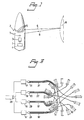
- Fig. 1 shows part of a missile indicated by reference numeral 1.
- the missile includes a proximity fuse section 2 which is housed in the missile in a per se known manner.
- the missile is provided with activation circuits 3 actuable by the proximity fuse, by means of which circuits the warhead 4 of the missile may be triggered or detonated.
- the transmitters of the proximity fuse are symbolized by a number of output openings 5 by the intermediary of which a plurality of narrow lobes 6 of optic radiation may be transmitted.
- the receiver of the proximity fuse is symbolized by a number of input openings 7 which may be exposed to optic radiation 8 deriving from the optical radiation emitted in part lobe form and reflected on a target 9.
- the number of transmitter devices is greater than the number of receiver devices, and one and the same input opening 7 constitutes the receiver input for the radiation from a plurality of output openings 5.
- the transmitter 10 shows a number of transmitter devices for optic radiation and are designated 101 ... 104; 111 ... 114; 121 ... 124; and 131 ... 134.
- Each respective transmitter device includes a per se known laser diode 1011 with associated collecting lens 1012. From each respective transmitter device, there departs a narrow part lobe 1013.
- the proximity fuse is an all-round sensor, which entails that the part lobes together cover the entire circumference of the proximity fuse (the missile).
- the transmitter devices are 16 in number.
- the transmitter devices may be divided into groups in two different manners, hereinafter designated first and second groups. Both the first and second groups are four in number. However, the number of groups may be varied.
- the transmitter devices 101, 111, 121, 131 form a first group.
- the transmitter devices 102, 112, 122, 132 form a second first group.
- the transmitter devices 103, 113, 123, 133; and 104, 114, 124 and 134 form the third and fourth first groups.
- the transmitter devices 101, 102, 103, 114 form a first second group.
- the transmitter devices 111, 112, 113, 114 form a second second group.
- the transmitter devices 121, 122, 123, 124; and 131, 132, 133, 134 form a third and fourth second group, respectively.
- the transmitter devices in each respective first group are energized from their drive unit 14, 15, 16 and 17, respectively.
- Energization from the drive unit 14 of the first first group is effected by the intermediary of electric lines 18.
- the drive units 15, 16 and 17 correspondingly energize their first groups by the intermediary of electric lines 19, 20 and 21.
- the transmitter devices included in each respective second group each cover their sector 22, 23, 24 and 25.
- the above-mentioned drive units 14-17 are controlled by a clock generator 26 which emits four parallel pulse trains for controlling each respective drive unit.
- the pulses/pulse trains are offset in relation to one another, such that the transmitter units within each respective second group are actuated in series from their respective drive unit.
- Activation from the drive units is, in this instance, such that the activation of one transmitter device in question within the group is initiated and terminated before activation is effected of subsequent transmitter devices, and so on.
- activation will be effected simultaneously of one transmitter device in each respective group.
- the simultaneously activated transmitter devices are, in this instance, directed substantially away from one another and, in the illustrated embodiment, all activated transmitter devices are arranged at 90° in relation to one another.
- the drive units may be constructed in a per se known manner by digital technology (flipflops, gates, etc.).
- the clock generator 26 may also consist of a per se known digital generator.
- the pulses in the pulse train from the clock generator are of the same amplitude and the mutual offset between the pulse trains may be arranged by previously known frequency distribution circuits in the clock generator.
- the pulse frequency is at most but a few kHz and the pulse time in each respective pulse train is shorter than 1 microsecond.
- Power supply is obtained in a per se known manner from a power source in the unit/missile.
- the number (m) of drive units is selected in dependence upon the number of first and second groups, respectively, and is preferably equal to the latter in number.
- a sensing circuit 27 is also connected to outputs on the drive units. The sensing circuit is intended to give an indication of that drive unit of the above-mentioned drive units which is activated at any given time.
- Fig. 3 shows an alternative embodiment of the transmitter.
- Electronic drive units 14′, 15′, 16′ and 17′ are also included in this particular embodiment and are driven by a digital clock generator 26′ in a manner corresponding to that according to the embodiment of Fig. 2.
- the drive units 14′-17′ are connected to LEDs or laser diodes 28, 29, 30 and 31, respectively.
- the ends of the fibre optic leads facing away from the above-mentioned transmitter units 28-31 are disposed at collecting lenses 32 of the same type as in the previously-described embodiment.
- the group arrangement and departing part lobes are disposed in a manner corresponding to that described in conjunction with the embodiment according to Fig. 2.
- Each respective now departing part lobe passes its associated opening 5 on the missile according to Fig. 1.
- the lens of the part lobe is disposed at each respective opening.
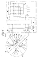
- Fig. 4 shows the receiver unit in the proximity fuse seen in a cross-sectional plane through the missile or the like.
- the sectors disclosed in Fig. 2 have also been included, having there been given the designations 22′, 23′, 24′ and 25′, respectively.
- the receiver comprises four receiver units 33, 34, 35 and 36 which each cover their sector of the incoming reflected radiation.
- Each respective receiver device displays a collimator lens 331 and a photodetector 332.
- the receiver devices 33-36 are arranged so as to cooperate with transmitter devices in each respective second group.
- the receiver device 33 may react to radiation transmitted by the transmitter devices 101, 102, 103, 104 and reflected on actual target.
- the receiver device 34 may react to transmitted radiation from the transmitter devices 111, 112, 113, 114 and reflected on the target, and so on.
- the radiation from each respective part lobe has been indicated.
- the received lobe 37 represents reflected radiation from the part lobe of the transmitter device 101.
- the incoming radiation 38, 39 and 40 respectively represents reflected radiation from the part lobes of the transmitter devices 102, 103 and 104.
- This incoming radiation 37-40 occurs successively in time sequence after one another.
- the lenses of the receivers are disposed at the openings 7 on the missile according to Fig. 1.
- the photodetectors in each respective receiver 33-36 are each connected to their amplifier 41-44.
- the outputs of the amplifiers are connected to a signal processing circuit 45 which processes received information in a per se known manner.
- the outputs of the amplifier circuits 41-44 are connected to sensing means 46.
- the sensors 27 of the transmitter devices and the sensors 46 of the receivers may, in one embodiment, be connected to a sensing matrix 47 to whose columns the outputs of the sensing circuit 27 are connected and to whose lines the outputs of the sensing circuit 46 are connected.
- Further sensing devices 48 are connected to the interstices in the matrix and, from the illustrated matrix sensing, it is possible to obtain, in the circuit 48, information as to that part lobe from which received radiation derives on each occasion.
- the lobe angles are selected to be so narrow that an individual lobe will, in its entirety, be accommodated on a smallest target which could be detectable even when the target is at the maximum detection range.
- the distribution angles between the different lobes are selected to be so small that one lobe always impinges upon the smallest target which it is possible to detect when it is at the maximum detection range.
- the lobe angles are suitably selected within the order of magnitude of between 5 and 45°, preferably within the range of between 5 and 30°.
- the transmitter and receiver devices may be disposed such that the lobes mutually overlap or not.
- the radiation of each respective part lobe reflected on the target and received in the missile may be identified and individually treated in relation to the radiation deriving from other part lobes.
- the missile fuselage is indicated by reference numeral 1 and its centre axis by reference numeral 49.
- the missile is fitted with a proximity fuse and here is illustrated only the receiving parts.
- the transmitter means of the proximity fuse are not shown, it being presupposed that these are of such type as emit the electromagnetic radiation in the form of narrow part lobes which, together, cover the entire circumference of the missile so that the emitted optical energy radiates outwardly in full circle.
- the number of part lobes may vary without in any manner effecting the inventive concept of the principles for receptive function as described in the following presentation.
- the receiver in the proximity fuse/missile is divided into at least two receiver units 52 and 53, the first receiver unit being intended to receive the first strobe 50 which impinges upon the robot in a direction R1, and the second receiver 53 is intended to receive the strobe 51 which impinges in a direction R2.
- the directions R1 and R2 are diametrically opposed to one another.
- the present invention functions for other mutual angles of incidence between the directions R1 and R2. The requirement is that the receivers must be directed in such a manner away from one another that the one receiver is not capable of receiving the part lobe of the other receiver when this is reflected on its largest imaginary target.
- Each respective receiver unit includes a collimator lens 52′ and 53′, respectively, and a photodetector 52 ⁇ and 53 ⁇ , respectively.
- the anode A1 in the first detector 52 ⁇ is interconnected, at a junction point S, with the cathode K2 in the detector 53 ⁇ .
- the cathode K1 in the detector 52 ⁇ is coupled to plus potential and the anode A2 in the detector 53 ⁇ is coupled to minus potential.
- An operational amplifier 54 of per se known type is connected, with its input 54a, to the above-mentioned interconnection point S.
- the output 54b of the operational amplifier is, in its turn, connected to a threshold circuit 55.
- This latter includes two threshold devices 55a, 55b of per se known type.
- the threshold devices are in the form of comparators with two inputs, the first inputs 55a′ and 55b′ respectively, being connected to the output 54b on the amplifier 54.
- the inputs 55a ⁇ and 55b ⁇ are each connected to their reference voltage which is realized by battery B′ and B ⁇ , respectively. Hence, the input 55a′ is connected to plus potential and the input 55b ⁇ to minus potential.
- the apparatus functions as follows. On an incoming strobe 50 from the direction R1, the receiver 52 is activated, in whose detector 52 ⁇ the pulse P1 then occurs. This pulse is amplified in the amplifier 54. The amplified pulse is impressed upon the input 55a′. If the amplitude in the pulse P1 exceeds a predetermined level, a signal will be obtained on the output 55a′′′. Using this signal, it is thus possible to single out the receiver section 52 activated on this particular occasion.
- the receiver section 53 will be correspondingly activated, whose detector 53 ⁇ gives the pulse P2.
- This latter pulse has a sign which is opposed to the sign in the pulse P1.
- the pulse P2 is amplified correspondingly in the amplifier 54 and the amplified pulse is impressed upon the input 55b′.
- the threshold 55b emits a signal on the output 55b′′′. The activated output thus singles out the receiver section 53 every time this is activated by an incoming strobe 51.
- the single-out function may also be employed within the missile for controlling its internal functions.
Landscapes
- Engineering & Computer Science (AREA)
- General Engineering & Computer Science (AREA)
- Physics & Mathematics (AREA)
- General Physics & Mathematics (AREA)
- Radar, Positioning & Navigation (AREA)
- Remote Sensing (AREA)
- Computer Networks & Wireless Communication (AREA)
- Optical Radar Systems And Details Thereof (AREA)
- Radar Systems Or Details Thereof (AREA)
- Air Bags (AREA)
- Geophysics And Detection Of Objects (AREA)
- Structure Of Receivers (AREA)
- Transplanting Machines (AREA)
- Investigating Or Analysing Materials By Optical Means (AREA)
- Aiming, Guidance, Guns With A Light Source, Armor, Camouflage, And Targets (AREA)
Priority Applications (1)
| Application Number | Priority Date | Filing Date | Title |
|---|---|---|---|
| EP92114850A EP0525822B1 (de) | 1986-12-11 | 1988-06-07 | Empfänger |
Applications Claiming Priority (1)
| Application Number | Priority Date | Filing Date | Title |
|---|---|---|---|
| SE8605332A SE460439C (sv) | 1986-12-11 | 1986-12-11 | Zonrör för robot, projektil eller liknande |
Related Child Applications (1)
| Application Number | Title | Priority Date | Filing Date |
|---|---|---|---|
| EP92114850.8 Division-Into | 1992-08-31 |
Publications (2)
| Publication Number | Publication Date |
|---|---|
| EP0345384A1 true EP0345384A1 (de) | 1989-12-13 |
| EP0345384B1 EP0345384B1 (de) | 1994-01-05 |
Family
ID=20366596
Family Applications (2)
| Application Number | Title | Priority Date | Filing Date |
|---|---|---|---|
| EP88201169A Expired - Lifetime EP0345384B1 (de) | 1986-12-11 | 1988-06-07 | Annäherungszünder |
| EP92114850A Expired - Lifetime EP0525822B1 (de) | 1986-12-11 | 1988-06-07 | Empfänger |
Family Applications After (1)
| Application Number | Title | Priority Date | Filing Date |
|---|---|---|---|
| EP92114850A Expired - Lifetime EP0525822B1 (de) | 1986-12-11 | 1988-06-07 | Empfänger |
Country Status (6)
| Country | Link |
|---|---|
| US (1) | US4903602A (de) |
| EP (2) | EP0345384B1 (de) |
| AT (2) | ATE99796T1 (de) |
| DE (2) | DE3855876T2 (de) |
| ES (2) | ES2099776T3 (de) |
| SE (1) | SE460439C (de) |
Families Citing this family (12)
| Publication number | Priority date | Publication date | Assignee | Title |
|---|---|---|---|---|
| DE3909188A1 (de) * | 1989-03-21 | 1990-09-27 | Messerschmitt Boelkow Blohm | Ausloesesensor |
| US5014621A (en) * | 1990-04-30 | 1991-05-14 | Motorola, Inc. | Optical target detector |
| PL175757B1 (pl) * | 1994-03-03 | 1999-02-26 | Geberit Technik Ag | Urządzenie do bezdotykowego sterowania instalacją sanitarną |
| US5753851A (en) * | 1997-06-16 | 1998-05-19 | The United States Of America As Represented By The Secretary Of The Army | Spinning mine with concentrated projectiles |
| US6718881B2 (en) * | 2001-09-07 | 2004-04-13 | Alliant Techsystems Inc. | Ordnance control and initiation system and related method |
| FR2873438B1 (fr) * | 2004-07-23 | 2006-11-17 | Tda Armements Sas Soc Par Acti | Procede et systeme d'activation de la charge d'une munition, munition equipee d'un dispositif d'activation a grande precision et systeme de neutralisation d'une cible |
| EP2318803B1 (de) * | 2008-08-08 | 2012-10-31 | MBDA UK Limited | Optischer annäherungszünder |
| EP2228619A1 (de) * | 2009-03-12 | 2010-09-15 | MBDA UK Limited | Optischer Näherungszünder |
| US10539403B2 (en) | 2017-06-09 | 2020-01-21 | Kaman Precision Products, Inc. | Laser guided bomb with proximity sensor |
| US10345087B2 (en) * | 2017-08-01 | 2019-07-09 | BAE Systems Informaticn and Electronic Systems Integration Inc. | Mid body seeker payload |
| US10935357B2 (en) | 2018-04-25 | 2021-03-02 | Bae Systems Information And Electronic Systems Integration Inc. | Proximity fuse having an E-field sensor |
| US11609073B2 (en) * | 2019-03-21 | 2023-03-21 | Corvid Technologies LLC | Munitions and methods for operating same |
Citations (4)
| Publication number | Priority date | Publication date | Assignee | Title |
|---|---|---|---|---|
| US4015530A (en) * | 1966-03-30 | 1977-04-05 | The United States Of America As Represented By The Secretary Of The Navy | Two channel optical fuzing system |
| US4306500A (en) * | 1978-09-05 | 1981-12-22 | General Dynamics, Pomona Division | Optical backscatter reduction technique |
| DE3424868C1 (de) * | 1984-07-06 | 1985-06-05 | Messerschmitt-Bölkow-Blohm GmbH, 8012 Ottobrunn | Zündsensoreinrichtung für Geschosse und Flugkörper |
| DE3531378A1 (de) * | 1985-09-03 | 1986-06-12 | Haberland, Rüdiger, Prof. Dr.-Ing., 6750 Kaiserslautern | Auswerteelektronik fuer differentialphotodioden |
Family Cites Families (4)
| Publication number | Priority date | Publication date | Assignee | Title |
|---|---|---|---|---|
| US2925965A (en) * | 1956-03-07 | 1960-02-23 | Collins Radio Co | Guided missile ordnance system |
| US3911438A (en) * | 1966-08-31 | 1975-10-07 | Us Navy | Proximity sensing device |
| US3793958A (en) * | 1972-06-22 | 1974-02-26 | Raytheon Co | Optical fusing arrangement |
| US4245560A (en) * | 1979-01-02 | 1981-01-20 | Raytheon Company | Antitank weapon system and elements therefor |
-
1986
- 1986-12-11 SE SE8605332A patent/SE460439C/sv not_active IP Right Cessation
-
1988
- 1988-06-07 DE DE3855876T patent/DE3855876T2/de not_active Expired - Lifetime
- 1988-06-07 DE DE88201169T patent/DE3886928T2/de not_active Expired - Fee Related
- 1988-06-07 EP EP88201169A patent/EP0345384B1/de not_active Expired - Lifetime
- 1988-06-07 AT AT88201169T patent/ATE99796T1/de not_active IP Right Cessation
- 1988-06-07 AT AT92114850T patent/ATE151887T1/de active
- 1988-06-07 ES ES92114850T patent/ES2099776T3/es not_active Expired - Lifetime
- 1988-06-07 ES ES88201169T patent/ES2047537T3/es not_active Expired - Lifetime
- 1988-06-07 EP EP92114850A patent/EP0525822B1/de not_active Expired - Lifetime
- 1988-06-10 US US07/205,247 patent/US4903602A/en not_active Expired - Fee Related
Patent Citations (4)
| Publication number | Priority date | Publication date | Assignee | Title |
|---|---|---|---|---|
| US4015530A (en) * | 1966-03-30 | 1977-04-05 | The United States Of America As Represented By The Secretary Of The Navy | Two channel optical fuzing system |
| US4306500A (en) * | 1978-09-05 | 1981-12-22 | General Dynamics, Pomona Division | Optical backscatter reduction technique |
| DE3424868C1 (de) * | 1984-07-06 | 1985-06-05 | Messerschmitt-Bölkow-Blohm GmbH, 8012 Ottobrunn | Zündsensoreinrichtung für Geschosse und Flugkörper |
| DE3531378A1 (de) * | 1985-09-03 | 1986-06-12 | Haberland, Rüdiger, Prof. Dr.-Ing., 6750 Kaiserslautern | Auswerteelektronik fuer differentialphotodioden |
Non-Patent Citations (1)
| Title |
|---|
| PATENT ABSTRACTS OF JAPAN, Vol. 9, No. 217 (P-387)(1940), September 4, 1985; & JP,A,60 076 676 (SOUGOU KEIBI HOSHIYOU K.K.) 01-05-1985, Abstract. * |
Also Published As
| Publication number | Publication date |
|---|---|
| DE3855876D1 (de) | 1997-05-22 |
| DE3886928T2 (de) | 1994-05-05 |
| SE460439C (sv) | 1999-06-14 |
| EP0525822A1 (de) | 1993-02-03 |
| ES2099776T3 (es) | 1997-06-01 |
| SE8605332L (sv) | 1988-06-12 |
| US4903602A (en) | 1990-02-27 |
| ES2047537T3 (es) | 1994-03-01 |
| ATE99796T1 (de) | 1994-01-15 |
| DE3855876T2 (de) | 1997-09-11 |
| SE460439B (sv) | 1989-10-09 |
| DE3886928D1 (de) | 1994-02-17 |
| EP0345384B1 (de) | 1994-01-05 |
| ATE151887T1 (de) | 1997-05-15 |
| EP0525822B1 (de) | 1997-04-16 |
| SE8605332D0 (sv) | 1986-12-11 |
Similar Documents
| Publication | Publication Date | Title |
|---|---|---|
| US5277113A (en) | Optical detection device | |
| US4903602A (en) | Proximity fuse | |
| US4086711A (en) | Laser hit indicator using reflective materials | |
| US5350134A (en) | Target identification systems | |
| US4859054A (en) | Proximity fuze | |
| US7193691B2 (en) | Active sensor receiver detector array for countermeasuring shoulder-fired missiles | |
| EP0208050B1 (de) | Annäherungszünder mit Entfernungseinstellung | |
| US5249470A (en) | Rotor blade tracking devices | |
| US4231533A (en) | Static self-contained laser seeker system for active missile guidance | |
| US3741111A (en) | Optical target sensor | |
| US5831724A (en) | Imaging lidar-based aim verification method and system | |
| US4047678A (en) | Modulated, dual frequency, optical tracking link for a command guidance missile system | |
| EP0108643B1 (de) | System zur Identifizierung von Tieren | |
| US3320420A (en) | Infrared detection system for use in early stages of missile launching | |
| US4896031A (en) | Proximity fuse optical radiation receiver having wedge-shaped damping filter positioned adjacent photocell | |
| US4222632A (en) | Light receiving and reflecting device | |
| US4213394A (en) | Spin processing active optical fuze | |
| US3942447A (en) | Fuzing system | |
| GB2122004A (en) | Apparatus for detection of incoming objects | |
| US4289960A (en) | Artillery training rounds target scoring system | |
| EP0392152A2 (de) | Infrarotannäherungszünder mit Doppelgesichtsfeld für bewegte Trägeranwendungen | |
| US20110164240A1 (en) | Sea clutter identification with a laser sensor for detecting a distant seaborne target | |
| USH333H (en) | Nonimaging identification structure | |
| US5142984A (en) | Optical detection device | |
| CA1335212C (en) | Target identification systems |
Legal Events
| Date | Code | Title | Description |
|---|---|---|---|
| PUAI | Public reference made under article 153(3) epc to a published international application that has entered the european phase |
Free format text: ORIGINAL CODE: 0009012 |
|
| AK | Designated contracting states |
Kind code of ref document: A1 Designated state(s): AT BE CH DE ES FR GB GR IT LI NL SE |
|
| 17P | Request for examination filed |
Effective date: 19900504 |
|
| 17Q | First examination report despatched |
Effective date: 19920122 |
|
| ITTA | It: last paid annual fee | ||
| GRAA | (expected) grant |
Free format text: ORIGINAL CODE: 0009210 |
|
| AK | Designated contracting states |
Kind code of ref document: B1 Designated state(s): AT BE CH DE ES FR GB GR IT LI NL SE |
|
| PG25 | Lapsed in a contracting state [announced via postgrant information from national office to epo] |
Ref country code: NL Effective date: 19940105 Ref country code: LI Effective date: 19940105 Ref country code: GR Free format text: LAPSE BECAUSE OF FAILURE TO SUBMIT A TRANSLATION OF THE DESCRIPTION OR TO PAY THE FEE WITHIN THE PRESCRIBED TIME-LIMIT Effective date: 19940105 Ref country code: CH Effective date: 19940105 Ref country code: BE Effective date: 19940105 Ref country code: AT Effective date: 19940105 |
|
| REF | Corresponds to: |
Ref document number: 99796 Country of ref document: AT Date of ref document: 19940115 Kind code of ref document: T |
|
| XX | Miscellaneous (additional remarks) |
Free format text: TEILANMELDUNG 92114850.8 EINGEREICHT AM 07/06/88. |
|
| ET | Fr: translation filed | ||
| REF | Corresponds to: |
Ref document number: 3886928 Country of ref document: DE Date of ref document: 19940217 |
|
| REG | Reference to a national code |
Ref country code: ES Ref legal event code: FG2A Ref document number: 2047537 Country of ref document: ES Kind code of ref document: T3 |
|
| ITF | It: translation for a ep patent filed | ||
| REG | Reference to a national code |
Ref country code: CH Ref legal event code: PL |
|
| NLV1 | Nl: lapsed or annulled due to failure to fulfill the requirements of art. 29p and 29m of the patents act | ||
| PLBE | No opposition filed within time limit |
Free format text: ORIGINAL CODE: 0009261 |
|
| STAA | Information on the status of an ep patent application or granted ep patent |
Free format text: STATUS: NO OPPOSITION FILED WITHIN TIME LIMIT |
|
| 26N | No opposition filed | ||
| EAL | Se: european patent in force in sweden |
Ref document number: 88201169.5 |
|
| PGFP | Annual fee paid to national office [announced via postgrant information from national office to epo] |
Ref country code: SE Payment date: 19980515 Year of fee payment: 11 Ref country code: FR Payment date: 19980515 Year of fee payment: 11 |
|
| PGFP | Annual fee paid to national office [announced via postgrant information from national office to epo] |
Ref country code: GB Payment date: 19980529 Year of fee payment: 11 |
|
| PGFP | Annual fee paid to national office [announced via postgrant information from national office to epo] |
Ref country code: ES Payment date: 19980608 Year of fee payment: 11 |
|
| PGFP | Annual fee paid to national office [announced via postgrant information from national office to epo] |
Ref country code: DE Payment date: 19980824 Year of fee payment: 11 |
|
| PG25 | Lapsed in a contracting state [announced via postgrant information from national office to epo] |
Ref country code: GB Free format text: LAPSE BECAUSE OF NON-PAYMENT OF DUE FEES Effective date: 19990607 |
|
| PG25 | Lapsed in a contracting state [announced via postgrant information from national office to epo] |
Ref country code: ES Free format text: LAPSE BECAUSE OF EXPIRATION OF PROTECTION Effective date: 19990608 |
|
| PG25 | Lapsed in a contracting state [announced via postgrant information from national office to epo] |
Ref country code: SE Free format text: THE PATENT HAS BEEN ANNULLED BY A DECISION OF A NATIONAL AUTHORITY Effective date: 19990629 |
|
| PG25 | Lapsed in a contracting state [announced via postgrant information from national office to epo] |
Ref country code: FR Free format text: THE PATENT HAS BEEN ANNULLED BY A DECISION OF A NATIONAL AUTHORITY Effective date: 19990630 |
|
| GBPC | Gb: european patent ceased through non-payment of renewal fee |
Effective date: 19990607 |
|
| EUG | Se: european patent has lapsed |
Ref document number: 88201169.5 |
|
| PG25 | Lapsed in a contracting state [announced via postgrant information from national office to epo] |
Ref country code: DE Free format text: LAPSE BECAUSE OF NON-PAYMENT OF DUE FEES Effective date: 20000503 |
|
| REG | Reference to a national code |
Ref country code: FR Ref legal event code: ST |
|
| REG | Reference to a national code |
Ref country code: ES Ref legal event code: FD2A Effective date: 20010601 |
|
| PG25 | Lapsed in a contracting state [announced via postgrant information from national office to epo] |
Ref country code: IT Free format text: LAPSE BECAUSE OF NON-PAYMENT OF DUE FEES;WARNING: LAPSES OF ITALIAN PATENTS WITH EFFECTIVE DATE BEFORE 2007 MAY HAVE OCCURRED AT ANY TIME BEFORE 2007. THE CORRECT EFFECTIVE DATE MAY BE DIFFERENT FROM THE ONE RECORDED. Effective date: 20050607 |