EP0345397A2 - Tennisschläger - Google Patents
Tennisschläger Download PDFInfo
- Publication number
- EP0345397A2 EP0345397A2 EP88311544A EP88311544A EP0345397A2 EP 0345397 A2 EP0345397 A2 EP 0345397A2 EP 88311544 A EP88311544 A EP 88311544A EP 88311544 A EP88311544 A EP 88311544A EP 0345397 A2 EP0345397 A2 EP 0345397A2
- Authority
- EP
- European Patent Office
- Prior art keywords
- frame
- racquet
- guide
- guides
- plane
- Prior art date
- Legal status (The legal status is an assumption and is not a legal conclusion. Google has not performed a legal analysis and makes no representation as to the accuracy of the status listed.)
- Withdrawn
Links
- 239000000463 material Substances 0.000 claims abstract description 21
- 230000035939 shock Effects 0.000 claims abstract description 15
- 230000002745 absorbent Effects 0.000 claims abstract description 11
- 239000002250 absorbent Substances 0.000 claims abstract description 11
- 230000000284 resting effect Effects 0.000 claims abstract description 8
- 239000000853 adhesive Substances 0.000 claims description 2
- 230000001070 adhesive effect Effects 0.000 claims description 2
- 239000004677 Nylon Substances 0.000 description 2
- 239000004809 Teflon Substances 0.000 description 2
- 229920006362 Teflon® Polymers 0.000 description 2
- 238000010276 construction Methods 0.000 description 2
- 229920001778 nylon Polymers 0.000 description 2
- 239000007787 solid Substances 0.000 description 2
- 235000009854 Cucurbita moschata Nutrition 0.000 description 1
- 240000001980 Cucurbita pepo Species 0.000 description 1
- 235000009852 Cucurbita pepo Nutrition 0.000 description 1
- 229920004943 Delrin® Polymers 0.000 description 1
- 239000002131 composite material Substances 0.000 description 1
- 239000004033 plastic Substances 0.000 description 1
- 230000001681 protective effect Effects 0.000 description 1
- 239000011359 shock absorbing material Substances 0.000 description 1
- 235000020354 squash Nutrition 0.000 description 1
- 210000000707 wrist Anatomy 0.000 description 1
Images


Classifications
-
- A—HUMAN NECESSITIES
- A63—SPORTS; GAMES; AMUSEMENTS
- A63B—APPARATUS FOR PHYSICAL TRAINING, GYMNASTICS, SWIMMING, CLIMBING, OR FENCING; BALL GAMES; TRAINING EQUIPMENT
- A63B49/00—Stringed rackets, e.g. for tennis
- A63B49/02—Frames
- A63B49/022—String guides on frames, e.g. grommets
Definitions
- Tennis racquets are strung with a single string which is threaded continuously through apertures in the racquet frame to form a grid, in the manner shown for instance in United States Patent No. 3,843,121 issued October 22, 1974 to Thomas B. Edlefson.
- the string is bent at a severe angle where it engages the frame.
- the grid is impacted by a ball the string stretches in those portions which are impacted but the tensile force is not distributed through the entire string because the string binds where it engages the frame. Consequently the tension in the string becomes uneven over the whole area of the grid.
- the invention consists of a racquet for tennis or the like, comprising: a circumferential frame with an appended handle; a plurality of guides mounted on the frame in spaced relationship along the frame in the plane thereof, each guide having at least an outwardly oriented portion concave transversely to the frame and being constructed of a self-lubricating and shock absorbing material; and a string laced over the guides in the concavities thereof to form a ball impact grid within the frame.
- the guides are spools positioned between a pair of laterally opposed members forming the frame and in another embodiment the guides are bosses fixed to the outside of the frame with tangential apertures through the frame. In a further embodiment the guides are spools resting in sockets or in a circumscribing channel on the frame in its plane.
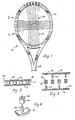
- FIG. 1 to 3 of the drawings consists of a tennis racquet 10 having an oval head or frame 12 with an appended handle 14.
- Frame 12 comprises a pair of spaced members 16 which are laterally opposed to each other with respect to the plane of the frame and carry between them a plurality of spaced sheaves or guides 18 each comprising a hollow cylindrical spool of self-lubricating and shock absorbent material having a concave circumferential surface 20 with a portion of the concavity being outwardly oriented with respect to the frame and being transverse to the frame.
- guides 18 are mounted for free rotation each on a pin 22 fixed on one frame member 16 and extending normally from that frame member to meet the opposing frame member, the frame members being held together by the pins which press fit into holes 23 and additionally may be glued in the holes.
- Frame 12 is strung by lacing a string 24 around each of guides 18 to form a ball impact grid 26.
- a ball striking grid 26 will produce shock and tensile forces in string 24 in the area of impact and the shock will be absorbed by guides 18 while the tension will be transmitted throughout the entire string because the string passes in an uninterrupted curve around guides 18.
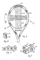
- the first alternate embodiment shown in Figures 5 to 7 of the drawings consists of a conventional racquet 30 having a solid circumferential frame 32 with an outside surface 34 in the plane of the frame and having spaced passages 35 about its circumference, the passages passing through the frame in the plane thereof to the outside surface.
- a ring of spaced, semi-cylindrical guides in the form of half sheaves or bosses 36 of self-lubricating and shock absorbent material are carried on surface 34 of racquet 30.
- Each boss 36 has a concave circumferential surface outwardly oriented with respect to the frame.
- each boss 36 has a cylindrical diameter equal to the shortest distance between any two passages 35 whereby the passages are substantially tangential to the bosses.
- each boss 36 may be a separate element carrying an adhesive protected by an overlying sheet of removable protective material 37 (a peel-off cover) which allows the boss to be fixed on frame 32.
- Rhquet 30 is prepared for stringing by adhering bosses 36 to outside surface 34 of frame 32 between each two adjacent apertures 35 as seen in Figures 6 and 7.
- Bosses 36 may be supplied in bulk for this purpose. Thereafter racquet 30 is strung by passing a string 40 through passages 35 and around bosses 36 in the usual manner to form a ball impact grid 42.
- bosses 36 can vary in diameter in accordance with the distance between any two passages 35 in order that string 40 will pass through the passages without touching them, thus preventing shock forces from passing into frame 32.
- the shock forces created in the string by a ball striking grid 26 will be absorbed by bosses 36 and the tensile forces will be distributed evenly throughout string 24 because the string passes around bosses 36 and has no angled bend to interfere with such forces.
- the second alternate embodiment shown in Figures 8 to 12 of the drawings consists of a racquet 50 having a solid circumferential fram 51 with a plurality of spaced outwardly opening sockets 52 each having sidewalls 54 and a bottom 56 which has a centrally disposed ridge 58 lying in the plane of the frame.
- a plurality of spaced passages 60 extend through frame 50 about its circumference, one pair of adjacent passages opening into each socket 52.
- Guides 62 each consisting of a cylindrical spool with a concave circumferential surface 64, rest one in each socket 52 astride ridge 58, the spool being located between adjacent passages 60.
- a circumferential groove 65 is centrally located in surface 64 of each guide 62.
- Guides 62 are held in sockets 52 by stringing racquet 50 to have a string 66 pass sequentially around each guide 62.
- the radius of groove 65 is only slightly larger than the radius of string 66 whereby the string is able to slip along the groove but lateral movement is inhibited.
- grooves similar to grooves 65 could be carried by guides 20 or bosses 36 in the previously described embodiments, and the grooves could comprise the concavities.
- This second embodiment allows pressure to be passed directly inwardly from guides 62 against frame 51 and also allows rotational movement of the guides.
- an outwardly opening channel 70 is located circumferentially about frame 51 in the plane of the frame.
- Channel 70 has a pair of opposed side walls 72 and a bottom74 with a centrally disposed longitudinal ridge 76.
- Guides 62 are held in channel 70 by strings 66 as before.
- Guides 18, bosses 36 and guides 62 are each formed of a self-lubricating and shock absorbent material, such as nylon, Teflon (a trade mark) or Delrin (a trade mark) or similar polymeric material, which provides a smooth, low friction and low wear surface. Such material is necessarily different from the material of frame 12 which is chosen to withstand stresses of another type.
- the invention is applicable to squash racquets or racquets of like construction used in other sports, and the shape of the frame may be other than oval, for example round.
- the plurality of guides 36 in Figures 5 to 7 could be replaced by a continuous composite strip 80 resting in a longitudinal, outwardly facing groove 82 in frame 12.
- Strip 80 comprises an inner element 84 of shock absorbent material and an outer element 86 cradled in the inner element out of contact with frame 12.
- Inner element 84 may be made of material such as teflon or nylon while outer element 86 may be made of material such as hard plastic.
- element 86 is shaped semi-cylindrically to form guides in the form of bosses 88 preferably each with an outwardly oriented concave circumferential surface 90.
- shock absorbent inner element 84 cradles outer element 86 which carries strings 40 and separates the outer element from frame 23 of racquet 10.
- Guides 88 could be formed separately from element 86.
- strip 80 could be set on the outer periphery of frame 12 without the existence of groove 82.
Landscapes
- Health & Medical Sciences (AREA)
- General Health & Medical Sciences (AREA)
- Physical Education & Sports Medicine (AREA)
- Golf Clubs (AREA)
- Vibration Dampers (AREA)
Applications Claiming Priority (6)
| Application Number | Priority Date | Filing Date | Title |
|---|---|---|---|
| US236832 | 1981-02-23 | ||
| US12838187A | 1987-12-03 | 1987-12-03 | |
| US128381 | 1987-12-03 | ||
| US23683288A | 1988-08-26 | 1988-08-26 | |
| US24933788A | 1988-09-26 | 1988-09-26 | |
| US249337 | 1988-09-26 |
Publications (2)
| Publication Number | Publication Date |
|---|---|
| EP0345397A2 true EP0345397A2 (de) | 1989-12-13 |
| EP0345397A3 EP0345397A3 (en) | 1990-10-31 |
Family
ID=27383724
Family Applications (1)
| Application Number | Title | Priority Date | Filing Date |
|---|---|---|---|
| EP19880311544 Withdrawn EP0345397A3 (en) | 1987-12-03 | 1988-12-06 | Tennis racquet |
Country Status (3)
| Country | Link |
|---|---|
| EP (1) | EP0345397A3 (de) |
| JP (1) | JPH01262878A (de) |
| AU (1) | AU2645388A (de) |
Cited By (1)
| Publication number | Priority date | Publication date | Assignee | Title |
|---|---|---|---|---|
| FR2820644A1 (fr) * | 2001-02-12 | 2002-08-16 | Babolat Vs | Element de garniture d'un cadre de raquette, cadre de raquette pourvu d'au moins un tel element et raquette comprenant un tel cadre |
Families Citing this family (1)
| Publication number | Priority date | Publication date | Assignee | Title |
|---|---|---|---|---|
| EP1151762A3 (de) * | 2000-04-28 | 2003-01-29 | Wilson Sporting Goods Company | Schläger mit Lagern im Rahmen zum Erleichtern der Bewegung der Schlägersaiten ausserhalb der Bespannungsfläche |
Family Cites Families (8)
| Publication number | Priority date | Publication date | Assignee | Title |
|---|---|---|---|---|
| GB309238A (en) * | 1928-01-11 | 1929-04-11 | Howard Brooks | Improvements in or relating to tennis racquets and like sports articles |
| FR826698A (fr) * | 1936-12-22 | 1938-04-06 | Raquette pour jeu de tennis et jeux analogues | |
| US3083968A (en) * | 1958-12-17 | 1963-04-02 | Takahashi Yoshiaki | Game racket construction |
| US3528658A (en) * | 1968-03-06 | 1970-09-15 | Charger Corp | Racket and method of making same |
| DE2611970A1 (de) * | 1976-03-20 | 1977-09-29 | Helmut Bausch | Tennisschlaeger |
| US4331331A (en) * | 1979-09-20 | 1982-05-25 | Leach Industries, Inc. | Game racquet and method of making |
| JPS59500628A (ja) * | 1982-03-30 | 1984-04-12 | フレキシボツクス リミテツド | メカニカル・シ−ルの改良 |
| FR2587903A1 (fr) * | 1985-09-28 | 1987-04-03 | Ramond Marcel | Raquette de tennis perfectionnee equipee d'un dispositif de tension de son cordage |
-
1988
- 1988-11-30 JP JP63303842A patent/JPH01262878A/ja active Pending
- 1988-12-01 AU AU26453/88A patent/AU2645388A/en not_active Abandoned
- 1988-12-06 EP EP19880311544 patent/EP0345397A3/en not_active Withdrawn
Cited By (1)
| Publication number | Priority date | Publication date | Assignee | Title |
|---|---|---|---|---|
| FR2820644A1 (fr) * | 2001-02-12 | 2002-08-16 | Babolat Vs | Element de garniture d'un cadre de raquette, cadre de raquette pourvu d'au moins un tel element et raquette comprenant un tel cadre |
Also Published As
| Publication number | Publication date |
|---|---|
| JPH01262878A (ja) | 1989-10-19 |
| AU2645388A (en) | 1989-06-08 |
| EP0345397A3 (en) | 1990-10-31 |
Similar Documents
| Publication | Publication Date | Title |
|---|---|---|
| US5054779A (en) | Tennis racquet | |
| US4595201A (en) | Tensionable racket having unique stringing pattern | |
| CA1124104A (en) | Transmission chain | |
| US6336877B1 (en) | Racket stringing guide recessed on the frame side | |
| US5141228A (en) | Shock absorbing string post for sports rackets | |
| CN101991937A (zh) | 具有铰接式护线管组件的球拍 | |
| CA1230354A (en) | Racket | |
| JP4295053B2 (ja) | スポーツ用ラケット | |
| US7297080B2 (en) | Game racquet with separate head and handle portions for reducing vibration | |
| US6840874B2 (en) | Game racquet with separate head and handle portions for reducing vibration | |
| US4889337A (en) | Racquet shock absorbing device | |
| US4997186A (en) | Racket frame having multi-dimensional cross-sectional construction | |
| EP0601701A2 (de) | Sportschläger, an dem alle Saiten schwingungsgedämpft sind | |
| EP0345397A2 (de) | Tennisschläger | |
| CN101428174A (zh) | 球类运动的球拍 | |
| US5232220A (en) | Ball game racket, especially for tennis or squash racket | |
| US4462592A (en) | Metallic frame for tennis rackets | |
| US4591165A (en) | Racket having strings which pass over rockable tension transmitting means | |
| EP0771224B1 (de) | Sportschläger mit leistungsring | |
| US5257781A (en) | Retained rocker string sports racket | |
| US4828260A (en) | Racquet vibration absorbing device | |
| US4930782A (en) | String tension transmitting apparatus | |
| US6935975B2 (en) | Racquet with channeled handle for receiving racquet string | |
| US5342044A (en) | Game racket | |
| US4366959A (en) | Racket for tennis and similar games |
Legal Events
| Date | Code | Title | Description |
|---|---|---|---|
| PUAI | Public reference made under article 153(3) epc to a published international application that has entered the european phase |
Free format text: ORIGINAL CODE: 0009012 |
|
| AK | Designated contracting states |
Kind code of ref document: A2 Designated state(s): DE FR GB IT |
|
| PUAL | Search report despatched |
Free format text: ORIGINAL CODE: 0009013 |
|
| AK | Designated contracting states |
Kind code of ref document: A3 Designated state(s): DE FR GB IT |
|
| STAA | Information on the status of an ep patent application or granted ep patent |
Free format text: STATUS: THE APPLICATION IS DEEMED TO BE WITHDRAWN |
|
| 18D | Application deemed to be withdrawn |
Effective date: 19910703 |
|
| APAF | Appeal reference modified |
Free format text: ORIGINAL CODE: EPIDOSCREFNE |