EP0345421B1 - Plateforme pour scène de théatre à hauteur réglable - Google Patents
Plateforme pour scène de théatre à hauteur réglable Download PDFInfo
- Publication number
- EP0345421B1 EP0345421B1 EP89103634A EP89103634A EP0345421B1 EP 0345421 B1 EP0345421 B1 EP 0345421B1 EP 89103634 A EP89103634 A EP 89103634A EP 89103634 A EP89103634 A EP 89103634A EP 0345421 B1 EP0345421 B1 EP 0345421B1
- Authority
- EP
- European Patent Office
- Prior art keywords
- platform
- stage platform
- height
- unlocking
- spindles
- Prior art date
- Legal status (The legal status is an assumption and is not a legal conclusion. Google has not performed a legal analysis and makes no representation as to the accuracy of the status listed.)
- Expired - Lifetime
Links
- 238000010168 coupling process Methods 0.000 claims description 21
- 238000005859 coupling reaction Methods 0.000 claims description 21
- 230000008878 coupling Effects 0.000 claims description 19
- 230000007246 mechanism Effects 0.000 claims description 7
- 230000005484 gravity Effects 0.000 claims description 2
- NJPPVKZQTLUDBO-UHFFFAOYSA-N novaluron Chemical compound C1=C(Cl)C(OC(F)(F)C(OC(F)(F)F)F)=CC=C1NC(=O)NC(=O)C1=C(F)C=CC=C1F NJPPVKZQTLUDBO-UHFFFAOYSA-N 0.000 description 34
- 210000002414 leg Anatomy 0.000 description 29
- 230000006835 compression Effects 0.000 description 8
- 238000007906 compression Methods 0.000 description 8
- 210000000689 upper leg Anatomy 0.000 description 4
- 206010017577 Gait disturbance Diseases 0.000 description 1
- 238000010276 construction Methods 0.000 description 1
- 230000000694 effects Effects 0.000 description 1
- 210000003746 feather Anatomy 0.000 description 1
- 230000000284 resting effect Effects 0.000 description 1
Images


Classifications
-
- F—MECHANICAL ENGINEERING; LIGHTING; HEATING; WEAPONS; BLASTING
- F16—ENGINEERING ELEMENTS AND UNITS; GENERAL MEASURES FOR PRODUCING AND MAINTAINING EFFECTIVE FUNCTIONING OF MACHINES OR INSTALLATIONS; THERMAL INSULATION IN GENERAL
- F16B—DEVICES FOR FASTENING OR SECURING CONSTRUCTIONAL ELEMENTS OR MACHINE PARTS TOGETHER, e.g. NAILS, BOLTS, CIRCLIPS, CLAMPS, CLIPS OR WEDGES; JOINTS OR JOINTING
- F16B7/00—Connections of rods or tubes, e.g. of non-circular section, mutually, including resilient connections
- F16B7/06—Turnbuckles
-
- E—FIXED CONSTRUCTIONS
- E04—BUILDING
- E04H—BUILDINGS OR LIKE STRUCTURES FOR PARTICULAR PURPOSES; SWIMMING OR SPLASH BATHS OR POOLS; MASTS; FENCING; TENTS OR CANOPIES, IN GENERAL
- E04H3/00—Buildings or groups of buildings for public or similar purposes; Institutions, e.g. infirmaries or prisons
- E04H3/10—Buildings or groups of buildings for public or similar purposes; Institutions, e.g. infirmaries or prisons for meetings, entertainments, or sports
- E04H3/22—Theatres; Concert halls; Studios for broadcasting, cinematography, television or similar purposes
- E04H3/24—Constructional features of stages
- E04H3/26—Revolving stages; Stages able to be lowered
Definitions
- the invention relates to a height-adjustable, rectangular pedestal for theater stages or the like.
- four scissors supporting a platform, of which two scissor legs are each guided and locked in the longitudinal direction of the platform, and with an unlocking device for unlocking the movable scissor legs for a height.
- Quick adjustment so that when the scissor legs are unlocked, a quick height adjustment can be carried out by lifting or lowering the platform by hand or by a quick drive.
- the movable scissor legs are articulated on slides which are guided on the longitudinal side rails of an upper frame carrying a platform and carry spring-loaded locking pins which are assigned locking holes on the longitudinal side rails.
- the locking bolts can be pulled out of the locking holes from the narrow sides of the pedestal using Bowden cables.
- the platform on its two narrow sides is brought to the desired new height by two people - after unlocking the pins can be executed very quickly.
- the platform can only be adjusted in height by the hole spacing on the long side rails.
- a pedestal which has a longitudinally extending under the platform screw with threaded nut pieces running on opposite thread sections, which are in driving connection with the upper ends of the displaceable scissor legs.
- the height is adjusted there by means of an electromotive drive that can be coupled to the spindle, but the locking of the movable scissor legs takes place in turn by means of spring-loaded locking pins which snap into holes in the longitudinal bars, which is why the platform pedestal there can only be adjusted in height in certain increments.
- screw spindles require an electric motor drive. If the thread pitch were so small that the spindle could be turned by hand, it would be very time-consuming to bring a folded pedestal, for example, to a height of 1 meter.
- DE-U 7332414 describes a continuously height-adjustable pedestal that has two screw spindles provided with opposite threads on each longitudinal side of the platform, on each of which a spindle nut runs, which is rigidly connected to a housing that is held in a torsion-proof manner along the platform frame and is displaceable along the platform frame which is articulated to one of the four movable scissor legs.
- the height of the pedestal can be infinitely adjusted by turning the screw spindles, but this is very time-consuming with large adjustment heights.
- the invention has for its object to provide a generic pedestal that is on the one hand very quickly and on the other hand continuously adjustable to any height.
- the pedestal according to the invention can be roughly adjusted and locked to the desired height, for example, by two people accessing the narrow sides of the platform after unlocking the scissor legs, but now the locking engagement is synonymous with coupling to a fine drive, through which the Scissor legs can still be moved sensitively and the platform can be adjusted exactly to the desired height.
- the movable scissor legs can each carry a coupling member to which a counter-coupling element on the drive side is assigned is which extends along the entire adjustment distance of the coupling member and is designed as a locking device for the respective height adjustment.
- a separately operable fine drive device can be provided for each pair of scissors.
- This makes it possible to incline the platform of the pedestal either obliquely in the longitudinal direction or in the transverse direction, for example to compensate for height differences between the right and left of the platform surfaces adjacent to the pedestal.
- the play between the individual components of the pedestal generally already allows fine adjustment of a height difference both between the longitudinal edges of the platform and between the transverse ends of the platform, i.e. thus an inclination adjustment in the longitudinal and transverse directions.
- the platform is thus adjustable in the manner of a swashplate.
- each fine drive device comprises a spindle which extends parallel to the longitudinal sides of the pedestal and has a self-locking thread
- the coupling members are each part nuts which can be engaged or disengaged by means of the unlocking device.
- spindles Since only relatively short adjustment paths are carried out by means of the spindles, these can be provided with a low, self-locking thread inclination, so that the spindles can now be actuated effortlessly via a drive handwheel or a hand crank.
- the displaceably guided part nuts can be withdrawn or lifted off the spindles against spring or gravity.
- Bowden cables, cable pulls or push or pull linkages can be provided, which are expediently operable from the transverse edge of the pedestal or from above through openings in the platform by means of hand or foot levers.
- the movable scissor legs are articulated on slides which are articulated on the longitudinal side members of an upper frame which supports the platform, each of which is penetrated by one of the spindles and in which one of the partial nuts is arranged in each case.
- the movable scissor legs can also be guided on longitudinal spars, which are arranged in the region of the pedestal base or base frame.
- the movable scissor legs of the pedestal in addition to their coupling members for the fine drive, each carry a spring-loaded latching pin, which are assigned latching holes on the longitudinal side members of the pedestal and which operate via a second, separately operable unlocking device the locking holes are retractable.
- the pedestal is therefore provided with two locking systems for height adjustment, both of which are released must be in order to carry out a quick height adjustment.
- the pedestal can be set in a simple manner, as is customary in the prior art (DE-PS 2305145), at predetermined height levels, which in practice can already meet the majority of the height settings required for a special stage structure.
- the coupling elements of the fine drive are now brought into engagement with the spindles and the locking bolts are withdrawn from the locking holes. Thereafter, the pedestal can then be continuously adjusted to the desired height or inclination by means of the fine drive, after which the coupling elements engaging in the spindle then effect the height locking.
- the unlocking devices for the coupling members of the fine drive can be fixed in their unlocking position, in which the coupling members are out of engagement with the counter coupling element on the drive side, or in which the locking bolts are withdrawn from the locking holes.
- the unlocking device for the fine drive coupling members consists of Bowden cables which are connected to a pawl mechanism are who, after a first tightening, holds the Bowden cables in the pulled-in unlocked position and only after a renewed tightening can the Bowden cables return to their basic position.
- a pawl mechanism makes it possible to completely disable the fine drive and thus to quickly and gradually adjust the pedestal in the usual manner and to lock it in place using the locking bolts.
- the fine drive can only be activated by pulling its assigned Bowden cables if necessary.
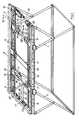
- FIG. 1 shows a pedestal with a platform 2 carried by a rectangular upper frame 1, here only indicated by dash-dotted lines, with a base frame 3 of the same size and with four Y-shaped scissors 4. While the shorter scissor arm 5 is articulated in the area of a corner of the upper frame 1 is, the other scissor leg 6, 7, 8, 9 is articulated at the bottom of a corner of the base frame 3 and at the top of a carriage 10. The carriage 10 can be moved on the side rails 11 of the upper frame 1.
- the pitch of the thread 21 of the part nut 19 and the pitch of the spindles 14, 15, 16, 17 is so small that self-locking is given and therefore the pedestal is securely locked in any height setting - with the part nuts 19 engaged.
- the partial nuts 19 are pulled off the spindles against the force of the compression spring 20 by means of unlocking devices 23 that can be actuated from the narrow sides of the pedestal, after which the platform, for example, gripped by two people on the narrow sides 2 can be moved up and down in "fast gear" as desired.
- 23 Bowden cables 24, 25, 26, 27 are provided as unlocking devices, of which two Bowden cables 24, 25 and 26, 27 can be actuated simultaneously via a common hand lever 28.
- the unlocking device arranged on the right transverse side member is not shown, but instead the cross-sectional profile of the upper frame 1 is illustrated.
- the Bowden cables 24 to 27 are released so that the partial nuts 19 snap into their spindles 14 to 17 and lock the height adjustment.
- the spindles 14 to 17, together with the partial nuts 19 that can be engaged and disengaged, represent a fine drive that allows a continuous fine height adjustment.
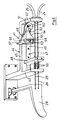
- the carriages 30 which can be moved along the longitudinal spars 29 also contain a guide part 31 lying under the extension part 18 for a locking bolt 33 loaded by a compression spring 32, to which 29 locking holes 34 are assigned on the longitudinal spars.
- the locking bolts 33 are by an unlocking device which comprises the Bowden cables 35, 36, 37, 38 can be tightened in pairs via a hand lever 39, 40, can be pulled out of the latching holes 34, and in Fig. 4 one of the latching bolts 33 is shown in the retracted unlocking position.
- the Bowden cable pairs 24, 25 and 26, 27 are each connected to a ratchet mechanism 41, which is shown in perspective in FIG. 6.
- the souls of the Bowden cables 24, 25 are fastened there to the hand lever 28 and pass through the U-legs 42, 43 of an approximately U-shaped bearing part 44, on the bottom leg 45 of which the longitudinal leg 46 of an angle piece is slidably mounted, on the other, parallel to it the two U-legs 42, 43 directed cross leg 48, the souls of the Bowden cables 24, 25 are each rigidly attached.
- a pawl 49 is pivotably mounted about an axis 50 perpendicular to the bottom leg against the force of a leg spring 51, the rear side of the pawl 49 resting against the longitudinal leg 46 of the angle piece 47.
- the pawl 49 is mounted in such a way that at its front end it can also be lifted a certain distance from the longitudinal leg 46 against the force of the leg spring 51 - in FIG. 6 from the plane of the illustration.
- any desired height adjustment can now be carried out using the fine drives.
- the hand levers 28 are first pulled again, the locking pin 53 reaching position 53 in the front pawl cutout 56, in which it no longer holds the pawl 49 up, which rather pivots about its axis 50 until it bends with its angled upper tongue 57 rests on the U-bearing part 44.
- the locking pin is in the position 53 'shown in dashed lines directly in front of the tongue 58 of the pawl which is angled slightly forward.
- the partial or locking nuts 19 are of relatively long design and are each loaded by a compression spring 20 at both longitudinal ends. Between the two compression springs, an arcuate channel 61 is formed in a back 60 of the partial nut 19, through which the associated Bowden cable 27 can be inserted from the outside until the Bowden cable end emerges again from the upper housing opening. The upper end 62 is then fixed. With this design, if a Bowden cable 24 to 27 breaks, it is possible to replace it without having to dismantle the slide 30.
- the invention is not restricted to the exemplary embodiments shown.
- the pedestals shown could also be constructed upside down, in which case the platform 2 would be removed from the upper frame 1 and mounted on the foot frame 3.
- cable pulls or pull rods can also be provided.
Landscapes
- Engineering & Computer Science (AREA)
- Architecture (AREA)
- General Engineering & Computer Science (AREA)
- Mechanical Engineering (AREA)
- Structural Engineering (AREA)
- Civil Engineering (AREA)
- Multimedia (AREA)
- Chairs For Special Purposes, Such As Reclining Chairs (AREA)
- Legs For Furniture In General (AREA)
- Circuit Arrangement For Electric Light Sources In General (AREA)
- Road Signs Or Road Markings (AREA)
- Harvester Elements (AREA)
- Accommodation For Nursing Or Treatment Tables (AREA)
- Flexible Shafts (AREA)
Claims (12)
Priority Applications (1)
| Application Number | Priority Date | Filing Date | Title |
|---|---|---|---|
| AT89103634T ATE71170T1 (de) | 1988-06-09 | 1989-03-02 | Hoehenverstellbarer podestbock fuer theaterbuehnen. |
Applications Claiming Priority (2)
| Application Number | Priority Date | Filing Date | Title |
|---|---|---|---|
| DE8807508U | 1988-06-09 | ||
| DE8807508U DE8807508U1 (de) | 1988-06-09 | 1988-06-09 | Höhenverstellbarer Podestbock für Theaterbühnen |
Publications (2)
| Publication Number | Publication Date |
|---|---|
| EP0345421A1 EP0345421A1 (fr) | 1989-12-13 |
| EP0345421B1 true EP0345421B1 (fr) | 1992-01-02 |
Family
ID=6824857
Family Applications (1)
| Application Number | Title | Priority Date | Filing Date |
|---|---|---|---|
| EP89103634A Expired - Lifetime EP0345421B1 (fr) | 1988-06-09 | 1989-03-02 | Plateforme pour scène de théatre à hauteur réglable |
Country Status (3)
| Country | Link |
|---|---|
| EP (1) | EP0345421B1 (fr) |
| AT (1) | ATE71170T1 (fr) |
| DE (2) | DE8807508U1 (fr) |
Cited By (1)
| Publication number | Priority date | Publication date | Assignee | Title |
|---|---|---|---|---|
| CN108843054A (zh) * | 2018-08-23 | 2018-11-20 | 广州马其纳工程技术有限公司 | 一种提拉式舞台 |
Families Citing this family (2)
| Publication number | Priority date | Publication date | Assignee | Title |
|---|---|---|---|---|
| US5727655A (en) * | 1996-07-12 | 1998-03-17 | Milliken Research Corporation | Platform lifter |
| DE102006002184B4 (de) * | 2005-01-20 | 2011-06-22 | Bühnenbau Schnakenberg GmbH & Co. KG, 42369 | Verfahren zum motorischen Anheben eines Scherenpodestes und Scherenpodest |
Family Cites Families (9)
| Publication number | Priority date | Publication date | Assignee | Title |
|---|---|---|---|---|
| DE7332414U (de) * | 1973-12-13 | Schroeder & Co Sico - Patent - Buehnen | Stufenlos hohenverstellbares Buhnen element für mobile Buhnen, Podien, Tribunen und dergleichen | |
| CH102173A (de) * | 1922-10-25 | 1923-11-16 | Fenestra Fabrik Fuer Eisenhoch | Transportwagen mit Heb- und Senkvorrichtung der Plattform. |
| US1794165A (en) * | 1929-08-01 | 1931-02-24 | W C And D J Casey | Automobile lift |
| US2740165A (en) * | 1954-11-16 | 1956-04-03 | Bryant L Ward | Convertible stage |
| US3345038A (en) * | 1965-10-08 | 1967-10-03 | Taylor Frederick George | Trailer jack |
| FR1459313A (fr) * | 1965-10-08 | 1966-04-29 | Dispositif de levage de plancher en particulier pour scène de théâtre | |
| FR2151497A5 (fr) * | 1971-08-31 | 1973-04-20 | Geffroy Jean | |
| DE2305145C2 (de) * | 1973-02-02 | 1975-03-06 | Hans Jochen 5600 Wuppertal Eisenberg | Von Hand höhenverstellbarer Podestbock für Theaterbühnen od.dgl |
| DE2941912A1 (de) * | 1979-10-17 | 1981-04-30 | Bühnenbau Rolf Schnakenberg GmbH & Co KG, 5600 Wuppertal | Hoehenverstellbarer, rechteckiger podestbock fuer theaterbuehnen o.dgl. |
-
1988
- 1988-06-09 DE DE8807508U patent/DE8807508U1/de not_active Expired
-
1989
- 1989-03-02 EP EP89103634A patent/EP0345421B1/fr not_active Expired - Lifetime
- 1989-03-02 DE DE8989103634T patent/DE58900657D1/de not_active Expired - Lifetime
- 1989-03-02 AT AT89103634T patent/ATE71170T1/de not_active IP Right Cessation
Cited By (1)
| Publication number | Priority date | Publication date | Assignee | Title |
|---|---|---|---|---|
| CN108843054A (zh) * | 2018-08-23 | 2018-11-20 | 广州马其纳工程技术有限公司 | 一种提拉式舞台 |
Also Published As
| Publication number | Publication date |
|---|---|
| DE8807508U1 (de) | 1989-10-12 |
| ATE71170T1 (de) | 1992-01-15 |
| EP0345421A1 (fr) | 1989-12-13 |
| DE58900657D1 (de) | 1992-02-13 |
Similar Documents
| Publication | Publication Date | Title |
|---|---|---|
| DE3003392A1 (de) | Hoehenverstellbarer podestbock fuer theaterbuehnen o.dgl. | |
| EP0034221B1 (fr) | Plateforme à tréteau déplaçable en hauteur pour scènes de théâtre ou analogues | |
| DE102019213710A1 (de) | Handwagen | |
| DE19815466A1 (de) | Be- und Entladegerät | |
| DE3636979C2 (fr) | ||
| DE4413444A1 (de) | Laderampe für Kraftfahrzeuge | |
| DE69228381T2 (de) | Faltbare bühne mit mehreren ebenen | |
| DE19525594A1 (de) | Motorisiertes Instandsetzungsgerät, insbesondere zur Instandsetzung eines Panzers | |
| DE3100163C2 (fr) | ||
| DE2524962A1 (de) | Oberschrank | |
| EP0345421A1 (fr) | Plateforme pour scène de théatre à hauteur réglable | |
| DE102019133319A1 (de) | Unterflurinstallationsbauteil | |
| DE3207177C2 (de) | Tisch mit einer in der Höhe und in der Neigung verstellbaren Tischplatte | |
| DE2941912C2 (fr) | ||
| EP2640557B1 (fr) | Table de travail, en particulier pour les ateliers | |
| DE3639216A1 (de) | Von hand hoehenverstellbarer podestbock | |
| DE1941803C3 (de) | Gleitführung mit Verriegelungsvorrichtung für klappbare Möbelteile, insbesondere zur Verwendung bei höhenverstellbaren Stühlen und Bänken | |
| DE19522967A1 (de) | Integrierbarer Kindersitz für einen Kraftfahrzeugsitz | |
| DE8620414U1 (de) | Hubpodium bzw. -podest | |
| EP1283129B1 (fr) | Marchepied escamotable pour camping-car ou caravan | |
| DE3831895C1 (fr) | ||
| DE4342016A1 (de) | Vorrichtung zum Verstellen der Höhe und/oder Neigung einer Tischplatte | |
| DE2943095C2 (fr) | ||
| DE19517227A1 (de) | Leiter | |
| EP0032226A2 (fr) | Ambulance automobile |
Legal Events
| Date | Code | Title | Description |
|---|---|---|---|
| PUAI | Public reference made under article 153(3) epc to a published international application that has entered the european phase |
Free format text: ORIGINAL CODE: 0009012 |
|
| AK | Designated contracting states |
Kind code of ref document: A1 Designated state(s): AT CH DE ES FR GB IT LI SE |
|
| 17P | Request for examination filed |
Effective date: 19900601 |
|
| 17Q | First examination report despatched |
Effective date: 19900927 |
|
| GRAA | (expected) grant |
Free format text: ORIGINAL CODE: 0009210 |
|
| AK | Designated contracting states |
Kind code of ref document: B1 Designated state(s): AT CH DE ES FR GB IT LI SE |
|
| PG25 | Lapsed in a contracting state [announced via postgrant information from national office to epo] |
Ref country code: SE Effective date: 19920102 Ref country code: IT Free format text: LAPSE BECAUSE OF FAILURE TO SUBMIT A TRANSLATION OF THE DESCRIPTION OR TO PAY THE FEE WITHIN THE PRE;WARNING: LAPSES OF ITALIAN PATENTS WITH EFFECTIVE DATE BEFORE 2007 MAY HAVE OCCURRED AT ANY TIME BEFORE 2007. THE CORRECT EFFECTIVE DATE MAY BE DIFFERENT FROM THE ONE RECORDED.SCRIBED TIME-LIMIT Effective date: 19920102 Ref country code: GB Effective date: 19920102 Ref country code: ES Free format text: THE PATENT HAS BEEN ANNULLED BY A DECISION OF A NATIONAL AUTHORITY Effective date: 19920102 |
|
| REF | Corresponds to: |
Ref document number: 71170 Country of ref document: AT Date of ref document: 19920115 Kind code of ref document: T |
|
| REF | Corresponds to: |
Ref document number: 58900657 Country of ref document: DE Date of ref document: 19920213 |
|
| PG25 | Lapsed in a contracting state [announced via postgrant information from national office to epo] |
Ref country code: AT Effective date: 19920302 |
|
| PG25 | Lapsed in a contracting state [announced via postgrant information from national office to epo] |
Ref country code: LI Effective date: 19920331 Ref country code: CH Effective date: 19920331 |
|
| EN | Fr: translation not filed | ||
| PG25 | Lapsed in a contracting state [announced via postgrant information from national office to epo] |
Ref country code: FR Effective date: 19920522 |
|
| GBV | Gb: ep patent (uk) treated as always having been void in accordance with gb section 77(7)/1977 [no translation filed] | ||
| PLBE | No opposition filed within time limit |
Free format text: ORIGINAL CODE: 0009261 |
|
| STAA | Information on the status of an ep patent application or granted ep patent |
Free format text: STATUS: NO OPPOSITION FILED WITHIN TIME LIMIT |
|
| REG | Reference to a national code |
Ref country code: CH Ref legal event code: AUV Free format text: DAS OBENGENANNTE PATENT IST, MANGELS BEZAHLUNG DER 4.JAHRESGEBUEHR, GELOESCHT WORDEN. Ref country code: CH Ref legal event code: PL |
|
| 26N | No opposition filed | ||
| REG | Reference to a national code |
Ref country code: FR Ref legal event code: ST |
|
| PGFP | Annual fee paid to national office [announced via postgrant information from national office to epo] |
Ref country code: DE Payment date: 19990305 Year of fee payment: 11 |
|
| PG25 | Lapsed in a contracting state [announced via postgrant information from national office to epo] |
Ref country code: DE Free format text: LAPSE BECAUSE OF NON-PAYMENT OF DUE FEES Effective date: 20010103 |