EP0345442A2 - Soupape de chasse d'eau avec détecteur électronique et clapet à solénoide - Google Patents
Soupape de chasse d'eau avec détecteur électronique et clapet à solénoide Download PDFInfo
- Publication number
- EP0345442A2 EP0345442A2 EP89106857A EP89106857A EP0345442A2 EP 0345442 A2 EP0345442 A2 EP 0345442A2 EP 89106857 A EP89106857 A EP 89106857A EP 89106857 A EP89106857 A EP 89106857A EP 0345442 A2 EP0345442 A2 EP 0345442A2
- Authority
- EP
- European Patent Office
- Prior art keywords
- solenoid
- valve body
- diaphragm
- cover
- outlet
- Prior art date
- Legal status (The legal status is an assumption and is not a legal conclusion. Google has not performed a legal analysis and makes no representation as to the accuracy of the status listed.)
- Withdrawn
Links
Images


Classifications
-
- F—MECHANICAL ENGINEERING; LIGHTING; HEATING; WEAPONS; BLASTING
- F16—ENGINEERING ELEMENTS AND UNITS; GENERAL MEASURES FOR PRODUCING AND MAINTAINING EFFECTIVE FUNCTIONING OF MACHINES OR INSTALLATIONS; THERMAL INSULATION IN GENERAL
- F16K—VALVES; TAPS; COCKS; ACTUATING-FLOATS; DEVICES FOR VENTING OR AERATING
- F16K31/00—Actuating devices; Operating means; Releasing devices
- F16K31/12—Actuating devices; Operating means; Releasing devices actuated by fluid
- F16K31/36—Actuating devices; Operating means; Releasing devices actuated by fluid in which fluid from the circuit is constantly supplied to the fluid motor
- F16K31/40—Actuating devices; Operating means; Releasing devices actuated by fluid in which fluid from the circuit is constantly supplied to the fluid motor with electrically-actuated member in the discharge of the motor
- F16K31/402—Actuating devices; Operating means; Releasing devices actuated by fluid in which fluid from the circuit is constantly supplied to the fluid motor with electrically-actuated member in the discharge of the motor acting on a diaphragm
-
- E—FIXED CONSTRUCTIONS
- E03—WATER SUPPLY; SEWERAGE
- E03D—WATER-CLOSETS OR URINALS WITH FLUSHING DEVICES; FLUSHING VALVES THEREFOR
- E03D3/00—Flushing devices operated by pressure of the water supply system flushing valves not connected to the water-supply main, also if air is blown in the water seal for a quick flushing
- E03D3/02—Self-closing flushing valves
- E03D3/06—Self-closing flushing valves with diaphragm valve and pressure chamber for retarding the valve-closing movement
-
- E—FIXED CONSTRUCTIONS
- E03—WATER SUPPLY; SEWERAGE
- E03D—WATER-CLOSETS OR URINALS WITH FLUSHING DEVICES; FLUSHING VALVES THEREFOR
- E03D5/00—Special constructions of flushing devices, e.g. closed flushing system
- E03D5/10—Special constructions of flushing devices, e.g. closed flushing system operated electrically, e.g. by a photo-cell; also combined with devices for opening or closing shutters in the bowl outlet and/or with devices for raising/or lowering seat and cover and/or for swiveling the bowl
- E03D5/105—Special constructions of flushing devices, e.g. closed flushing system operated electrically, e.g. by a photo-cell; also combined with devices for opening or closing shutters in the bowl outlet and/or with devices for raising/or lowering seat and cover and/or for swiveling the bowl touchless, e.g. using sensors
-
- Y—GENERAL TAGGING OF NEW TECHNOLOGICAL DEVELOPMENTS; GENERAL TAGGING OF CROSS-SECTIONAL TECHNOLOGIES SPANNING OVER SEVERAL SECTIONS OF THE IPC; TECHNICAL SUBJECTS COVERED BY FORMER USPC CROSS-REFERENCE ART COLLECTIONS [XRACs] AND DIGESTS
- Y10—TECHNICAL SUBJECTS COVERED BY FORMER USPC
- Y10S—TECHNICAL SUBJECTS COVERED BY FORMER USPC CROSS-REFERENCE ART COLLECTIONS [XRACs] AND DIGESTS
- Y10S4/00—Baths, closets, sinks, and spittoons
- Y10S4/03—Electric flushing
Definitions
- This invention is concerned with a flush valve which is rendered operative in response to activation by an electronic sensor. More particularly, the invention is concerned with an electronic sensor and solenoid valve contained in a single unit for operating a flush valve.
- the invention is concerned with improving the operation of a diaphragm-type flush valve which is rendered operative by means of an external handle.
- a heretofore known conventional flush valve of the diaphragm-type operated by an external handle there is a water inlet and a water outlet on a conventional flush valve, the outlet being connected to a device such as a urinal which is to be flushed; and the inlet and outlet are separated by a diaphragm so as to provide two chambers, an upper and a lower chamber, filled with water at supply line pressure.
- the external handle is depressed and operates an operating stem which pushes against the stem of an auxiliary valve and thereby tilts the head of the auxiliary valve off from its auxiliary valve seat.
- the upper chamber releases a quantity of water into the outlet.
- the diaphragm is completely moved off its seat, which diaphragm normally closes off the outlet of the flush valve, and then the inlet and lower chamber provide for a continuous flow of a quantity of water from the lower chamber into the outlet of the flush valve.
- the flushing action continues until enough water enters the upper chamber through a bypass orifice in the diaphragm to refill the upper chamber and equalize the pressure to that of the lower chamber.
- the area of the diaphragm subject to pressure on the upper side of the diaphragm is greater than the area subject to pressure on the lower side. Therefore once the pressure has been equalized, the diaphragm begins to slowly descend to the main valve seat and closes off the flow of water and completes the cycle.
- a solenoid-type operated flush valve or an electrically operated flush valve from U.S. Patent No. 3,011,751 to John J. Delany and Edwin C. Baisel.
- Use is made of main and auxiliary bleed ports which are directly and successively opened by the solenoid plunger. Opening of the auxiliary bleed port by the initial movement of the plunger reduces the pressure above the main bleed port in order to effect rapid opening thereof.
- the plunger of the flush valve forms an integral part of the solenoid and controls the direct flow of water from the upper chamber of one side of the diaphragm into the outlet so as to render the inlet and outlet in direct communication and have the water flow from the inlet to the lower chamber and then into the outlet.
- This device uses contact the body of the flush electrical wires which may valve.
- Another object of the present invention is to provide for retro-fitting and of a conventional diaphragm type flush valve by merely removing the handle and top cover providing a novel valve body cover and a control module to provide for and permit operation of the flush valve without the use of an external handle.
- a further object of the invention is to provide a solenoid valve and a solenoid valve body therefor for a sensor operated flush valve to render the flush valve operable.
- Yet another object of the invention is to provide a replacement operating mechanism for a standard manufacturers flush valve and replace the conventional cover with a novel replacement cover and control module containing a solenoid valve and a sensor module, and a solenoid valve controlled by the solenoid and which cooperates with the cover and the remainder of the conventional flush valve.
- the invention consists in the provision of a sensor operated flush valve, such as for a urinal or a water closet, in which the flush valve has a valve body with a water inlet and a water outlet, and a valve body cover for the valve body, and cooperating connection elements on the valve body and the housing, respectively for holding the housing to the valve body in a water tight fitting relationship while permitting separation thereof; a diaphragm held in a fixed relationship between the valve body and the cover for separating the inlet from the outlet, and by-pass means associated with the diaphragm for permitting water under pressure supplied to the water inlet to pass into the cover; a solenoid valve associated with and an electronic component casing associated with the cover; received within the cover a solenoid housed within the component casing, a solenoid plunger associated with the solenoid and the solenoid valve; the cover having a through opening communicating with the solenoid valve, the solenoid valve including a first water passageway communicating with the interior of the flush valve passageway communicating with the
- the invention also contemplates a cover and a control module housing for a conventional flush valve which is to replace the conventional cover.
- the cover and control module housing according to the invention includes a sensing device and a hand-free operating mechanism therefor.
- the flush valve is associated with an infra-red sensing device and a solenoid valve which is rendered operative in response thereto to operate a solenoid for controlling the flushing operations.
- the infra-red light sensor includes a transmitter for directing an infra-red light pulse towards an object, such as an individual within a particular predetermined range, and a receiving device for receiving or capturing reflections of the transmitted light pulse reflected from the object or individual within the predetermined range.
- circuitry is provided for converting the reflected pulse into controlled electronic signals to open and close a solenoid valve so as to operate the conventional flush valve without the use of an external handle.
- control the solenoid and the solenoid valve by external means separate and apart from the infra-red sensor mechanism or in conjunction with the infra-red sensor mechanism.
- a separate transmitter can be used to transmit a signal from an external source to the electrical circuitry within the control module for operation thereof so that no external wiring goes to the control module.
- the control module is operable with twenty-four volts A.C. which is connected to twenty-four volts D.C. or less using some milliamperes with small power requirements so that should a fault in the circuitry occur, there is no possibility of external shock to a user of the urinal or other device to which the flush valve is attached. This is an important safety feature over the earlier heretofore known devices.
- FIG. 1 show the presently preferred mode for carrying out the invention according to the teachings of the present invention and illustrate a flush valve 10 having a conventional water inlet 12 having an axis as shown by arrow 13 and forming a transverse axis, a conventional water outlet 14 having an axis as shown by arrow 15 forming a longitudinal axis of the flush valve, a valve body 16, and additionally including according to the invention a novel valve body cover 18, an operating or control portion or module 20 containing novel control elements as explained later.
- a diaphragm 22 is held at one end 24 thereof between valve body 16 and valve body cover 18. End 24 is firmly held in a water-tight manner between surface 17 on valve body 16 and scaling edge 19 on valve body cover 18.
- the conventional cover is different from novel cover 18, but the holding of the one end 24 between the novel valve body cover 18 and valve body 16 forms no part of the invention.
- the center portion of conventional diaphragm 22 also includes a central opening 26 that is in communication with water outlet 14.
- Diaphragm 22 also includes a bypass valve 28 so as to permit water to flow from inlet 12 into the volume or upper chamber 39 between an upper face 30 of diaphragm 22 and cover 18.
- Flush valve 10 also includes a main valve seat member 32 and a diaphragm bushing holder 34 having a first holding portion 35 and a second holding portion 36 positioned on opposite sides of the other end 37 of diaphragm 22 proximate to and surrounding central opening 26 and positioned to hold the portion of bushing around central opening 26 in a tight manner while permitting movement of diaphragm 22 off from main valve seat 32.
- Diaphragm 22 divides the flush valve into a lower chamber 38 and the upper chamber 39. Diaphragm 22 forms with valve body 16 and inlet 12 the lower chamber 38.
- Valve body cover 18 forms with diaphragm 22 the upper chamber 39 with bypass valve 28 providing for communication between lower chamber 38 and upper chamber 39 to supply water from inlet 12 to the lower chamber 38 and thence to the upper chamber 39 through bypass valve 28 in order to fill the upper chamber 39 through diaphragm 22.
- bypass valve 28 providing for communication between lower chamber 38 and upper chamber 39 to supply water from inlet 12 to the lower chamber 38 and thence to the upper chamber 39 through bypass valve 28 in order to fill the upper chamber 39 through diaphragm 22.
- bypass valve 28 providing for communication between lower chamber 38 and upper chamber 39 to supply water from inlet 12 to the lower chamber 38 and thence to the upper chamber 39 through bypass valve 28 in order to fill the upper chamber 39 through diaphragm 22.
- bypass valve 28 providing for communication between lower chamber 38 and upper chamber 39 to supply water from inlet 12 to the lower chamber 38 and thence to the upper chamber 39 through bypass valve 28 in order to fill the upper chamber 39 through diaphragm 22.
- Diaphragm bushing holder 34 which includes lower or first holding portion 35, upper or second holding portion 36, a cup-shaped member 31 and a disc or metal washer 33. Cup-shaped member 31, disc 33 and upper holding portion 36 are threaded in a complementary manner to lower holding portion 35 for holding other end 37 of diaphragm 22 so that diaphragm 22 and diaphragm bushing holder 34 move as a unit.
- Control module 20 positioned on valve body cover 18 includes an electronic cover 40 containing part of a solenoid valve 42 which includes a solenoid 44 for movement of and operating of a solenoid plunger 46 and a solenoid valve body 48 received within a cup-shaped opening portion 50 in valve body cover 18.
- Valve body cover 18 is provided with a roof portion 82 to provide for opening 50 to be aligned with solenoid valve 42 to cooperate together with diaphragm 22 and main valve seat member 32 to provide for water flow through the solenoid valve body 48 to outlet 14.
- Cover opening 50 is substantially U-shaped in section and includes a base 49 to support and hold the solenoid valve body 48 and a leg portion 51 which surrounds the valve body 48.
- Solenoid 44 fits within opening 50 and provides a water-tight fit with cover 18 to prevent water from coming into contact with the inside of electronic cover 40.
- Solenoid valve body 48 includes a first passageway 52 communicating between upper chamber 39 and a second passageway 54 having one end proximate to plunger 46 and closed off by plunger 46 which is held by gravity against solenoid valve body 48, and its other end communicating with and opening to outlet 14.
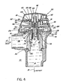
- plunger 46 When solenoid 44 is activated, plunger 46 is raised and is moved in a vertical direction so as to be drawn upwardly, as shown in Figure 3 of the drawing, into the solenoid 44 so as to remove it from engagement with solenoid valve body 48, and thereby first and second passageways 52 and 54 are open to each other as shown by curved arrow 55 and rendered in communication with each other by means of a third passageway 56 so that water can flow from upper chamber 39 through first passageway 52, through third passageway 56 and thence into second passageway 54 and into outlet 14. This reduces the pressure in chamber 39 and relieves the pressure balance in chamber 39 so that the pressure on diaphragm 22 from chamber 38 is greater than the pressure from chamber 39.
- Plunger 46 is retained in its elevated position for a predetermined period of time in accordance with a pre-set time of flush which can be pre-set in the electronic circuitry. After the pre-set period of time, plunger 46 drops due to gravity to close off the connecting passageway 56.
- Solenoid 44 in operation is controlled by and rendered operative by means of an infra-red sensor mechanism 57 which includes an infra-red transmitter 58 and an infra-red receiver 59.
- an infra-red filter 60 Positioned in front of infra-red transmitter 58 is an infra-red filter 60 and positioned in front of infra-red receiver 59 is an infra-red filter 61.
- the infra-red transmitter 58 and infra-red receiver 59 are connected with circuitry 62 shown schematically which renders plunger 46 moveable in response to the energization of solenoid 44.
- the infra-red transmitter 58 and infra-red receiver 59 including the schematic circuitry 62 associated therewith are held and supported by holder 64. While it is not an essential element of the invention, it is desired that the circuitry and the holder as well as the portions of the transmitter 58, receiver 59, and filters 60, 61 be potted as shown at 66 in Figure 3, but omitted from other views for sake of clarity and held within electronic cover 40 so as to avoid any moisture contamination. Potting 66 may be a clear see-through type of plastic so that all internal parts are visible, and at the same time contamination from moisture is prevented.
- the potting compound can also be formed from a hard compound in which a block is formed from black epoxy or the circuit elements can be sprayed on with a clear material which also seals all of the elements.
- the lower portion of lower holding portion 35 forms a water guide 68.
- the diaphragm bushing holder 34 is held to second holding portion 36 by the upper portion of guide 68 to sandwich the other end 37 of diaphragm 22 and, one side of guide 68 surrounds central opening 26.
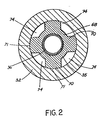
- the other side of guide 68 includes four substantially equally spaced legs 70 extending transversely of the longitudinal axis of outlet 14 and in a direction along the transverse axis of inlet 12. The ends of legs 70 abut against side 71 of main valve seat member 32 and together therewith provide for passageways 74 for the flow of water from inlet 12 to outlet 14 when diaphragm 22 is moved away from seating portion 72 of main valve seat member.
- Main valve seat member 32 can,if desired, include peripherally spaced legs 70 projecting therefrom and cooperate with guide 68 to provide passageways 74. If main valve seat member 32 includes legs 70, then the legs abut against the guide 68 which forms a unitary member lower holding portion 35. What is important is that one or more passageways 74 be provided between guide 68 and side 71 of main valve seat member 32.
- Main valve seat 32 is provided with the seating portion 72 on which diaphragm 22 normally sits in its closed position to seal off chambers 38 and 39 from each other, and to assure that diaphragm 22 is held against seating portion 72 by the water pressure in upper chamber 39.
- Legs 70 are also used to provide alignment control for cylindrically-shaped guide 68 as it moves relative to main valve seat member 32 in a vertical or longitudinal direction axially of the longitudinal axis 15 of outlet 14 as shown in the drawing. Between each pair of adjacent legs 70, there is provided the water passageway 74 to permit water from inlet 12 and chamber 38 to flow to outlet 14 when the diaphragm 22 is shown in its raised or open position as shown in Figure 4.
- Legs 70 guide the vertical movement of the upper holding portion 36 of diaphragm bushing holder 34 as diaphragm 22 moves in an upward direction axially along the longitudinal axis as shown by the arrow 15 to provide communication between inlet 12, lower chamber 38 and outlet 14 through channel 76 formed between seating portion 72 and diaphragm 22 when in its raised position as best seen in Figure 4 to permit water to flow in the direction of arrows 78; channel 76 is in effect provided when diaphragm 22 is moved off seating portion 72 in an upward direction along longitudinal axis 15 away from seating portion 72.
- a conventional choke 80 Below the legs 70, there is provided a conventional choke 80.
- Valve body cover 18 includes a roof portion 82 having a central portion 84 forming the base 49 and leg portion 51, including a first opening 86 in base 49 in communication with first passageway 52, an outer circumferential extension 85 having at the end thereof sealing edge 19 to clamp one end 24 of diaphragm 22 between face plate or bearing plate 87, and a second opening 88 in base 49 in communication with second passageway 54 for receiving a mating portion 90 of solenoid valve body 48 both of which are provided with mating threaded portions 89, 91, respectively or any other suitable mating connectors.
- Extending from valve body cover 18 is a cylindrical member 92 which extends into diaphragm bushing holder 34 through the central opening in diaphragm 22 and passes through central opening 26.
- cylindrical member 92 is provided on an outer circumferential portion thereof with a circumferential channel 93 to receive a cup washer 94.
- Cup washer 94 extends circumferentially about the outer peripheral extent of cylindrical member 92 and expands to create a tight seal as it expands between second holding portion 36 and cylindrical member 92.
- This cup washer 94 provides for a permanent separation between outlet 14 and upper chamber 39 while permitting second holding portion 36 to move axially along cylindrical member 92 in the direction of longitudinal axis 15.
- Solenoid chamber O-rings 96 are also provided to provide a tight seal between valve body cover 18 and control module 20 and more specifically between solenoid valve body 48 and base 49 in central portion 84.
- Outer cover 40 of control module 20 may also be provided with a decorative front portion 98.
- the flush valve is rendered operative when an object such as an individual is within the range of infra-red sensor mechanism 57 and a transmitted infra-red ray from infra-red transmitter 58 is reflected back from the object or person (not shown) when such object is within a preselected range or distance and is received by infra-red receiver 59, then solenoid 44 is rendered operative and plunger 46 is raised and moved in an upward direction longitudinally along axis 15 as shown in the drawing, and the first and second passageways 52, 54 respectively are rendered in communication through third passageway 56 (as best seen in Figure 3) and the water in upper chamber 39 goes through the second passageway 54 into outlet 14.
- Outer circumferential extension 85 of cover 18 is in contact with diaphragm 22 and holds the outer end of diaphragm 22 on face plate or bearing plate 87 of valve body 16, and diaphragm bushing holder 34 cooperates with seating portion 72 to hold diaphragm 22 in place and prevent flow of water from inlet 12 to outlet 14 and to permit flow of water when diaphragm 22 is moved off seating portion 72 when sensor activated to activate the flush valve to move plunger 46 and provide for flushing a urinal or water closet.
- the electronic module, solenoid and sensor to activate the flush valve are all contained in a single unit in control module 20 and are potted in potting 66 to prevent contamination by water and the outside environment.
- the sensor mechanism 57 includes a power on reset circuit that makes use of a resistor-capacitor network and a voltage threshold comparing device to create a time delay that will inhibit the operation of the flush valve for a nominal pre-selected time period when current is first supplied to the sensor. Thus, the sensor cannot activate if the user steps up to the unit and steps away for less than a pre-selected predetermined period of time.
- the replacement unit includes the valve body cover 18 and the outer cover 40 of control module 20 containing the solenoid 44, solenoid valve 42 and a decorative front portion 98 of the cover containing the sensor module or sensor mechanism 57.
- Electronic circuitry 62 of the low voltage type, twenty-four volts or less, is contained within unit for controlling the time the solenoid maintains the solenoid valve body 48 with plunger 46 away from the solenoid valve body 48 and in its open position, and the circuitry also includes means for controlling the length, duration and commencement time of flushing in response to the infra-red sensor mechanism 57.
- the guide extends from the cover containing the solenoid valve with a passage to the outlet of the flush valve. The guide slides into the unmodified portion of the flush valves diaphragm assembly.
Landscapes
- Engineering & Computer Science (AREA)
- General Engineering & Computer Science (AREA)
- Health & Medical Sciences (AREA)
- Life Sciences & Earth Sciences (AREA)
- Hydrology & Water Resources (AREA)
- Public Health (AREA)
- Water Supply & Treatment (AREA)
- Mechanical Engineering (AREA)
- Aviation & Aerospace Engineering (AREA)
- Magnetically Actuated Valves (AREA)
- Sanitary Device For Flush Toilet (AREA)
Applications Claiming Priority (2)
| Application Number | Priority Date | Filing Date | Title |
|---|---|---|---|
| US183042 | 1988-04-19 | ||
| US07/183,042 US4793588A (en) | 1988-04-19 | 1988-04-19 | Flush valve with an electronic sensor and solenoid valve |
Publications (2)
| Publication Number | Publication Date |
|---|---|
| EP0345442A2 true EP0345442A2 (fr) | 1989-12-13 |
| EP0345442A3 EP0345442A3 (fr) | 1990-03-07 |
Family
ID=22671187
Family Applications (1)
| Application Number | Title | Priority Date | Filing Date |
|---|---|---|---|
| EP89106857A Withdrawn EP0345442A3 (fr) | 1988-04-19 | 1989-04-17 | Soupape de chasse d'eau avec détecteur électronique et clapet à solénoide |
Country Status (3)
| Country | Link |
|---|---|
| US (1) | US4793588A (fr) |
| EP (1) | EP0345442A3 (fr) |
| CA (1) | CA1320716C (fr) |
Cited By (5)
| Publication number | Priority date | Publication date | Assignee | Title |
|---|---|---|---|---|
| FR2668517A1 (fr) * | 1990-10-31 | 1992-04-30 | Asamade Joseph | Appareil sanitaire pour l'evacuation forcee d'eaux usees. |
| GB2268942A (en) * | 1992-07-24 | 1994-01-26 | Cistermiser Ltd | Electrical control apparatus for flushing system |
| DE4328064A1 (de) * | 1992-08-21 | 1994-02-24 | Sloan Valve Co | Sensor- und batteriebetriebenes Spülventil mit Membrananschlag |
| WO2003002824A1 (fr) * | 2001-06-28 | 2003-01-09 | Isidro Gonzalez Benavides | Debitmetre electronique a joint mobile |
| EP1144889A4 (fr) * | 1998-12-23 | 2005-03-16 | Goyen Controls Co | Soupape de commande d'ecoulement d'air |
Families Citing this family (101)
| Publication number | Priority date | Publication date | Assignee | Title |
|---|---|---|---|---|
| US4914758A (en) * | 1988-06-27 | 1990-04-10 | Bauer Industries Inc. | Fresh water control system and method |
| US5175892A (en) * | 1988-06-27 | 1993-01-05 | Bauer Industries, Inc. | Fresh water control system and method |
| US4941215A (en) * | 1989-01-19 | 1990-07-17 | Liu Su Haw | Automatic flushing device for a flush toilet |
| US4911401A (en) * | 1989-05-15 | 1990-03-27 | The Toro Company | Valve having improved bleed assembly |
| US4915347A (en) * | 1989-05-18 | 1990-04-10 | Kohler Co. | Solenoid operated faucet |
| USD328488S (en) | 1989-09-05 | 1992-08-04 | Bauer Industries, Inc. | Adaptor assembly unit for converting a manual flush valve to electrical operation |
| US5438714A (en) * | 1989-10-31 | 1995-08-08 | Bauer Industries, Inc. | Fresh water manifold distribution system and method |
| US4971287A (en) * | 1989-11-28 | 1990-11-20 | Bauer Industries, Inc. | Solenoid operated flush valve and flow control adapter valve insert therefor |
| CA2015417C (fr) * | 1990-04-25 | 1996-06-25 | Su-Hwa Liu | Dispositif automatique de chasse pour w.-c. |
| JP3072773B2 (ja) * | 1990-10-27 | 2000-08-07 | 株式会社椿井 | 自動尿量測定装置 |
| US5062453A (en) * | 1991-03-06 | 1991-11-05 | Zurn Industries, Inc. | On demand sensor flush valve |
| US5125621A (en) * | 1991-04-01 | 1992-06-30 | Recurrent Solutions Limited Partnership | Flush system |
| GB2261532B (en) * | 1991-11-20 | 1994-11-23 | Chen Chi Electro Chemical | Automatic flushing device |
| US5169118A (en) * | 1992-02-11 | 1992-12-08 | Sloan Valve Company | Sensor-operated battery-powered flush valve |
| JP3128790B2 (ja) * | 1992-06-15 | 2001-01-29 | 東陶機器株式会社 | 給水制御装置 |
| US5195720A (en) | 1992-07-22 | 1993-03-23 | Sloan Valve Company | Flush valve cover |
| GB2270932B (en) * | 1992-09-29 | 1996-02-07 | Liao Su Lan | Automatic flushing apparatus for urinals |
| IL104235A (en) * | 1992-12-25 | 1997-11-20 | Bermad Fa | Valve particularly useful in fire extinguishing systems |
| IT1262712B (it) * | 1993-03-18 | 1996-07-04 | Sol Spa | Perfezionamenti ai rubinetti miscelatori a comando elettronico |
| US5313673A (en) * | 1993-03-19 | 1994-05-24 | Zurn Industries, Inc. | Electronic flush valve arrangement |
| US5431181A (en) * | 1993-10-01 | 1995-07-11 | Zurn Industries, Inc. | Automatic valve assembly |
| US5508510A (en) * | 1993-11-23 | 1996-04-16 | Coyne & Delany Co. | Pulsed infrared sensor to detect the presence of a person or object whereupon a solenoid is activated to regulate fluid flow |
| US5584465A (en) * | 1993-12-07 | 1996-12-17 | Snap-Tite, Inc. | Solenoid latching valve |
| US5432959A (en) * | 1994-01-05 | 1995-07-18 | Dakota Technologies Corp. | System for regulating water flow in a toilet |
| US5680879A (en) * | 1994-09-12 | 1997-10-28 | Technical Concepts, Inc. | Automatic flush valve actuation apparatus for replacing manual flush handles |
| US5535781A (en) * | 1995-01-04 | 1996-07-16 | Speakman Company | Push button flush activation system for urinal |
| USD377520S (en) * | 1995-04-20 | 1997-01-21 | Zurn Industries, Inc. | Faucet control casing |
| US5611517A (en) * | 1995-04-20 | 1997-03-18 | Zurn Industries, Inc. | Control unit for automatic faucet |
| CA2301081A1 (fr) * | 1997-08-14 | 1999-02-25 | Isidro Gonzalez Benavides | Robinet de chasse d'eau pourvu d'un systeme de desodorisation et desinfection, avec une seule piece en mouvement, commande par capteur ou bouton electronique |
| US6056261A (en) * | 1997-10-31 | 2000-05-02 | Sloan Valve Company | Sensor-operated solenoid direct drive flush valve |
| US6299127B1 (en) | 2000-06-23 | 2001-10-09 | Sloan Valve Company | Solenoid valve piston |
| US6349921B1 (en) | 2000-07-03 | 2002-02-26 | Sloan Valve Company | Institutional flush valve operating system |
| US6382586B1 (en) * | 2000-12-14 | 2002-05-07 | Sloan Valve Company | Flush valve assembly with flex tube |
| US6499152B2 (en) | 2001-01-18 | 2002-12-31 | Geberit Technik Ag | Flush controller |
| US6560790B2 (en) | 2001-03-06 | 2003-05-13 | Geberit Technik Ag | Flush control |
| US20030015416A1 (en) * | 2001-07-02 | 2003-01-23 | Meeeh Robert F. | Apparatus for stimulating removal of electrolytic energy from fluids |
| US7921480B2 (en) | 2001-11-20 | 2011-04-12 | Parsons Natan E | Passive sensors and control algorithms for faucets and bathroom flushers |
| US7437778B2 (en) | 2001-12-04 | 2008-10-21 | Arichell Technologies Inc. | Automatic bathroom flushers |
| US6685158B2 (en) * | 2001-12-04 | 2004-02-03 | Arichell Technologies, Inc. | Assembly of solenoid-controlled pilot-operated valve |
| EP1451415B1 (fr) | 2001-12-04 | 2007-08-29 | Arichell Technologies, Inc. | Chasse d'eau automatique |
| US6619614B2 (en) * | 2001-12-04 | 2003-09-16 | Arichell Technologies, Inc. | Automatic flow controller employing energy-conservation mode |
| US7396000B2 (en) | 2001-12-04 | 2008-07-08 | Arichell Technologies Inc | Passive sensors for automatic faucets and bathroom flushers |
| US7367541B2 (en) * | 2001-12-21 | 2008-05-06 | Technical Concepts, Llc | Automatic flush valve actuation apparatus |
| EP1466118A4 (fr) | 2001-12-26 | 2008-11-12 | Arichell Tech Inc | Dispositifs de chasse d'eau equipes de nouveaux capteurs et regulateurs |
| US9169626B2 (en) | 2003-02-20 | 2015-10-27 | Fatih Guler | Automatic bathroom flushers |
| WO2004005628A2 (fr) | 2002-06-24 | 2004-01-15 | Arichell Technologies, Inc. | Systemes de distribution d'eau automatises a commande asservie |
| US7124997B2 (en) * | 2002-09-23 | 2006-10-24 | Sloan Valve Company | Flush valve assembly with flex tube |
| US7185876B2 (en) * | 2002-10-12 | 2007-03-06 | Technical Concepts, Llc | Overrun braking system and method |
| US7731154B2 (en) | 2002-12-04 | 2010-06-08 | Parsons Natan E | Passive sensors for automatic faucets and bathroom flushers |
| CA2458063C (fr) | 2003-02-20 | 2013-04-30 | Arichell Technologies, Inc. | Chasses d'eau de conception modulaire |
| USD598974S1 (en) | 2004-02-20 | 2009-08-25 | Sloan Valve Company | Automatic bathroom flusher cover |
| US6845524B2 (en) * | 2003-06-11 | 2005-01-25 | Hydrotek Corporation | Manual and automatic flusher |
| JP3861206B2 (ja) * | 2003-12-08 | 2006-12-20 | 株式会社フジキン | 流体制御器 |
| USD600781S1 (en) | 2004-02-20 | 2009-09-22 | Sloan Valve Company | Enclosure for automatic bathroom flusher |
| USD600318S1 (en) | 2004-02-20 | 2009-09-15 | Sloan Valve Company | Enclosure for automatic bathroom flusher |
| USD600782S1 (en) | 2004-02-20 | 2009-09-22 | Sloan Valve Company | Enclosure for automatic bathroom flusher |
| USD598976S1 (en) | 2004-02-20 | 2009-08-25 | Sloan Valve Company | Enclosure for automatic bathroom flusher |
| USD601224S1 (en) | 2004-02-20 | 2009-09-29 | Sloan Valve Company | Enclosure for automatic bathroom flusher |
| USD620554S1 (en) | 2004-02-20 | 2010-07-27 | Sloan Valve Company | Enclosure for automatic bathroom flusher |
| USD621909S1 (en) | 2004-02-20 | 2010-08-17 | Sloan Valve Company | Enclosure for automatic bathroom flusher |
| USD623268S1 (en) | 2004-02-20 | 2010-09-07 | Sloan Valve Company | Enclosure for automatic bathroom flusher |
| USD599435S1 (en) | 2004-02-20 | 2009-09-01 | Sloan Valve Company | Enclosure for automatic bathroom flusher |
| USD599886S1 (en) | 2004-02-20 | 2009-09-08 | Sloan Valve Company | Enclosure for automatic bathroom flusher |
| USD629069S1 (en) | 2004-02-20 | 2010-12-14 | Sloan Valve Company | Enclosure for automatic bathroom flusher |
| USD598977S1 (en) | 2004-02-20 | 2009-08-25 | Sloan Valve Company | Enclosure for automatic bathroom flusher |
| USD599436S1 (en) | 2004-02-20 | 2009-09-01 | Sloan Valve Company | Enclosure for automatic bathroom flusher |
| USD598978S1 (en) | 2004-02-20 | 2009-08-25 | Sloan Valve Company | Enclosure for automatic bathroom flusher |
| USD602561S1 (en) | 2004-02-20 | 2009-10-20 | Sloan Valve Company | Enclosure for automatic bathroom flusher |
| USD599885S1 (en) | 2004-02-20 | 2009-09-08 | Sloan Valve Company | Enclosure for automatic bathroom flusher |
| USD598975S1 (en) | 2004-02-20 | 2009-08-25 | Sloan Valve Company | Enclosure for automatic bathroom flusher |
| US6837264B1 (en) | 2004-03-11 | 2005-01-04 | Mjsi, Inc. | Toilet fill valve with valve lock |
| US7743436B1 (en) | 2004-03-11 | 2010-06-29 | Mjsi, Inc. | Toilet fill valve with adjustable bowl fill flow |
| US6823889B1 (en) | 2004-03-11 | 2004-11-30 | Mjsi, Inc. | Toilet fill valve with adjustable bowl fill flow |
| US7082624B2 (en) * | 2004-12-22 | 2006-08-01 | Flushtech Corporation | Water-separating apparatus for toilet tank |
| US8590067B2 (en) * | 2005-02-03 | 2013-11-26 | Danco, Inc. | Control of toilet bowl fill flow |
| WO2006088937A2 (fr) | 2005-02-16 | 2006-08-24 | Mjsi, Inc. | Limiteur de debit au robinet de remplissage de reservoir de chasse d'eau et procede |
| US7484420B2 (en) * | 2005-10-18 | 2009-02-03 | Mjsi, Inc. | Fastener assembly and method |
| US7926511B1 (en) | 2006-04-21 | 2011-04-19 | Mjsi, Inc. | Toilet fill valve with valve lock |
| US7952261B2 (en) | 2007-06-29 | 2011-05-31 | Bayer Materialscience Ag | Electroactive polymer transducers for sensory feedback applications |
| EP2239793A1 (fr) | 2009-04-11 | 2010-10-13 | Bayer MaterialScience AG | Montage de film polymère électrique commutable et son utilisation |
| US8485496B2 (en) * | 2009-11-23 | 2013-07-16 | Sloan Valve Company | Electronic flush valve with optional manual override |
| USD635219S1 (en) | 2010-04-20 | 2011-03-29 | Zurn Industries, LCC | Flush valve actuator |
| WO2012118916A2 (fr) | 2011-03-01 | 2012-09-07 | Bayer Materialscience Ag | Procédés de fabrication automatisés pour la production de dispositifs et de films polymères déformables |
| JP2014517331A (ja) | 2011-03-22 | 2014-07-17 | バイエル・インテレクチュアル・プロパティ・ゲゼルシャフト・ミット・ベシュレンクテル・ハフツング | 電場応答性高分子アクチュエータレンチキュラシステム |
| US8585007B2 (en) * | 2011-07-20 | 2013-11-19 | Bayer Intellectual Property, GmbH | Valve operated by its own medium |
| US9876160B2 (en) | 2012-03-21 | 2018-01-23 | Parker-Hannifin Corporation | Roll-to-roll manufacturing processes for producing self-healing electroactive polymer devices |
| US9222584B2 (en) | 2012-04-20 | 2015-12-29 | Sdb Ip Holdings, Llc | Rigid piston retrofit for a diaphragm flush valve |
| CA2946628C (fr) * | 2012-04-20 | 2018-05-15 | Sdb Ip Holdings, Llc | Piston rigide adapte a un robinet de chasse a membrane |
| KR20150031285A (ko) | 2012-06-18 | 2015-03-23 | 바이엘 인텔렉쳐 프로퍼티 게엠베하 | 연신 공정을 위한 연신 프레임 |
| US9590193B2 (en) | 2012-10-24 | 2017-03-07 | Parker-Hannifin Corporation | Polymer diode |
| US20140117265A1 (en) | 2012-10-26 | 2014-05-01 | Kohler Co. | Dispensing device and battery package |
| EP2813628B1 (fr) | 2013-03-15 | 2019-02-27 | Sloane Valve Company | Commande de chasse à double mode |
| EP2813627A1 (fr) | 2013-03-15 | 2014-12-17 | Sloan Valve Company | Actionneur de chasse d'eau automatique comprenant une commande manuelle additionelle |
| US10578228B2 (en) | 2016-09-26 | 2020-03-03 | Zurn Industries, Llc | Sensing mechanism for valve operation |
| US10753075B2 (en) * | 2016-09-26 | 2020-08-25 | Zurn Industries, Llc | Flush valve |
| US10689837B2 (en) | 2016-12-15 | 2020-06-23 | Kohler Co. | Flushometer |
| US10047873B2 (en) | 2017-01-10 | 2018-08-14 | Masco Canada Limited | Cover assembly for an automatic flushometer |
| US10487486B2 (en) * | 2017-02-08 | 2019-11-26 | Zurn Industries, Llc | Flush valve with relief valve having axially-translatable valve element |
| US10975559B2 (en) | 2018-01-31 | 2021-04-13 | Mac Faucets, Llc | Electronic flush valve system for tankless water fixtures |
| USD883444S1 (en) | 2018-12-04 | 2020-05-05 | Zurn Industries, Llc | Flush valve housing |
| USD1103340S1 (en) | 2023-03-21 | 2025-11-25 | Kohler Co. | Flush valve housing |
Family Cites Families (13)
| Publication number | Priority date | Publication date | Assignee | Title |
|---|---|---|---|---|
| US1614468A (en) * | 1924-06-05 | 1927-01-18 | Haas Philip | Hydraulically-operated flushing-valve mechanism |
| US3011751A (en) * | 1957-03-18 | 1961-12-05 | Delany Realty Corp | Electrically operated flush valve |
| US3079952A (en) * | 1959-12-28 | 1963-03-05 | Jackes Evans Mfg Company | Valve |
| US3291439A (en) * | 1963-02-08 | 1966-12-13 | Goldstein Mira | Push-button flushing valve |
| US3202396A (en) * | 1964-06-02 | 1965-08-24 | Coyne & Delany Co | Pilot operated diaphragm flush valve |
| US3493008A (en) * | 1966-10-10 | 1970-02-03 | Paul J Scaglione | Pressure balanced regulating valve |
| US4295631A (en) * | 1980-03-21 | 1981-10-20 | Allen Walter E | Solenoid operated valve |
| US4309781A (en) * | 1980-05-09 | 1982-01-12 | Sloan Valve Company | Automatic flushing system |
| AU1403283A (en) * | 1983-04-28 | 1984-11-01 | Automatic Switch Company | Dual flow rate valve |
| JPS6040440A (ja) * | 1983-08-11 | 1985-03-02 | 松下電工株式会社 | 便器水洗装置 |
| US4624017A (en) * | 1983-12-20 | 1986-11-25 | Foletta John D | Automatic flushing system |
| US4604764A (en) * | 1984-10-03 | 1986-08-12 | Fava Enzo | Tap for the delivery of liquids for the conversion from automatic to manual |
| US4709427A (en) * | 1985-09-30 | 1987-12-01 | Coyne & Delany Co. | Disabler system for plumbing fixture |
-
1988
- 1988-04-19 US US07/183,042 patent/US4793588A/en not_active Expired - Fee Related
-
1989
- 1989-03-29 CA CA000595078A patent/CA1320716C/fr not_active Expired - Fee Related
- 1989-04-17 EP EP89106857A patent/EP0345442A3/fr not_active Withdrawn
Cited By (8)
| Publication number | Priority date | Publication date | Assignee | Title |
|---|---|---|---|---|
| FR2668517A1 (fr) * | 1990-10-31 | 1992-04-30 | Asamade Joseph | Appareil sanitaire pour l'evacuation forcee d'eaux usees. |
| EP0484213A1 (fr) * | 1990-10-31 | 1992-05-06 | Joseph Asamade | Appareil sanitaire pour l'évacuation forcée d'eaux usées |
| GB2268942A (en) * | 1992-07-24 | 1994-01-26 | Cistermiser Ltd | Electrical control apparatus for flushing system |
| GB2268942B (en) * | 1992-07-24 | 1995-10-04 | Cistermiser Ltd | Control apparatus for flushing systems |
| DE4328064A1 (de) * | 1992-08-21 | 1994-02-24 | Sloan Valve Co | Sensor- und batteriebetriebenes Spülventil mit Membrananschlag |
| DE4328064C2 (de) * | 1992-08-21 | 1999-03-25 | Sloan Valve Co | Spülventil für Sanitärzwecke |
| EP1144889A4 (fr) * | 1998-12-23 | 2005-03-16 | Goyen Controls Co | Soupape de commande d'ecoulement d'air |
| WO2003002824A1 (fr) * | 2001-06-28 | 2003-01-09 | Isidro Gonzalez Benavides | Debitmetre electronique a joint mobile |
Also Published As
| Publication number | Publication date |
|---|---|
| EP0345442A3 (fr) | 1990-03-07 |
| CA1320716C (fr) | 1993-07-27 |
| US4793588A (en) | 1988-12-27 |
Similar Documents
| Publication | Publication Date | Title |
|---|---|---|
| US4793588A (en) | Flush valve with an electronic sensor and solenoid valve | |
| CA2245449C (fr) | Dispositif de derivation et de filtration pour robinet de chasse | |
| US5169118A (en) | Sensor-operated battery-powered flush valve | |
| CA2045099C (fr) | Commande d'evacuation pour vannes de refoulement | |
| JP5160007B2 (ja) | 自動タンク式フラッシャ | |
| CA2133256C (fr) | Soupape automatique | |
| EP0353096B1 (fr) | Obturateur à fermeture automatique | |
| EP0828103B1 (fr) | Soupape à flotteur | |
| GB2149534A (en) | Liquid level control system | |
| EP0321376B1 (fr) | Appareil pour contrôler la mise en marche et l'arrêt d'une pompe hydraulique | |
| GB2159503A (en) | Filling means for filling receptacles with liquid | |
| US3115643A (en) | Electrical flush valve actuating means | |
| EP1162320B1 (fr) | Dispositif pour le rinçage d'une cuvette de toilette ou analogue | |
| US5920919A (en) | Toilet flush system | |
| US5513394A (en) | Chemicals mixed type automatic flushing device | |
| CA2946626C (fr) | Robinet a piston rigide comprenant un solenoide | |
| JPS6350697A (ja) | 給水装置の制御配設 | |
| JPH0752209Y2 (ja) | 水洗便器用洗浄弁ユニット | |
| US5448784A (en) | Urinal assembly and electrically actuated valve for same | |
| US5195558A (en) | Automatic/manual double-function urinal flush valve | |
| DE3165089D1 (en) | Valve unit for water closets | |
| US5788217A (en) | Cuspidor water supply valving | |
| WO2002084035A1 (fr) | Systeme de chasse d'eau pour toilettes ou urinoirs | |
| AU725659B2 (en) | Flush system | |
| JPH0718488B2 (ja) | 遮断弁 |
Legal Events
| Date | Code | Title | Description |
|---|---|---|---|
| PUAI | Public reference made under article 153(3) epc to a published international application that has entered the european phase |
Free format text: ORIGINAL CODE: 0009012 |
|
| AK | Designated contracting states |
Kind code of ref document: A2 Designated state(s): DE FR GB IT |
|
| PUAL | Search report despatched |
Free format text: ORIGINAL CODE: 0009013 |
|
| AK | Designated contracting states |
Kind code of ref document: A3 Designated state(s): DE FR GB IT |
|
| 17P | Request for examination filed |
Effective date: 19900816 |
|
| 17Q | First examination report despatched |
Effective date: 19911029 |
|
| STAA | Information on the status of an ep patent application or granted ep patent |
Free format text: STATUS: THE APPLICATION IS DEEMED TO BE WITHDRAWN |
|
| 18D | Application deemed to be withdrawn |
Effective date: 19911105 |