EP0345498A1 - Gerät zur Entkeimung und Desodorisierung von Räumen - Google Patents
Gerät zur Entkeimung und Desodorisierung von Räumen Download PDFInfo
- Publication number
- EP0345498A1 EP0345498A1 EP89108929A EP89108929A EP0345498A1 EP 0345498 A1 EP0345498 A1 EP 0345498A1 EP 89108929 A EP89108929 A EP 89108929A EP 89108929 A EP89108929 A EP 89108929A EP 0345498 A1 EP0345498 A1 EP 0345498A1
- Authority
- EP
- European Patent Office
- Prior art keywords
- electrode
- insulator
- circuit
- voltage
- converter
- Prior art date
- Legal status (The legal status is an assumption and is not a legal conclusion. Google has not performed a legal analysis and makes no representation as to the accuracy of the status listed.)
- Granted
Links
- 238000004659 sterilization and disinfection Methods 0.000 title claims description 8
- 238000004332 deodorization Methods 0.000 title claims description 5
- 239000012212 insulator Substances 0.000 claims abstract description 19
- 150000001875 compounds Chemical class 0.000 claims description 6
- 229910052751 metal Inorganic materials 0.000 claims description 6
- 239000002184 metal Substances 0.000 claims description 6
- 238000005266 casting Methods 0.000 claims description 5
- 229910001369 Brass Inorganic materials 0.000 claims description 4
- RYGMFSIKBFXOCR-UHFFFAOYSA-N Copper Chemical compound [Cu] RYGMFSIKBFXOCR-UHFFFAOYSA-N 0.000 claims description 4
- 229910000831 Steel Inorganic materials 0.000 claims description 4
- 229910052782 aluminium Inorganic materials 0.000 claims description 4
- XAGFODPZIPBFFR-UHFFFAOYSA-N aluminium Chemical compound [Al] XAGFODPZIPBFFR-UHFFFAOYSA-N 0.000 claims description 4
- 239000010951 brass Substances 0.000 claims description 4
- 229910052802 copper Inorganic materials 0.000 claims description 4
- 239000010949 copper Substances 0.000 claims description 4
- 239000004033 plastic Substances 0.000 claims description 4
- 229920003023 plastic Polymers 0.000 claims description 4
- 239000010959 steel Substances 0.000 claims description 4
- 238000001816 cooling Methods 0.000 claims description 3
- 239000011521 glass Substances 0.000 claims description 3
- 230000001681 protective effect Effects 0.000 claims description 3
- 238000010276 construction Methods 0.000 claims description 2
- 230000000903 blocking effect Effects 0.000 claims 1
- 239000011888 foil Substances 0.000 claims 1
- 239000004814 polyurethane Substances 0.000 claims 1
- 239000004800 polyvinyl chloride Substances 0.000 claims 1
- 238000004382 potting Methods 0.000 claims 1
- 238000005057 refrigeration Methods 0.000 claims 1
- 229910052760 oxygen Inorganic materials 0.000 abstract description 3
- 239000001301 oxygen Substances 0.000 abstract description 3
- -1 oxygen ions Chemical class 0.000 abstract description 3
- 241000894006 Bacteria Species 0.000 abstract description 2
- CBENFWSGALASAD-UHFFFAOYSA-N Ozone Chemical compound [O-][O+]=O CBENFWSGALASAD-UHFFFAOYSA-N 0.000 description 4
- 229940125810 compound 20 Drugs 0.000 description 3
- JAXFJECJQZDFJS-XHEPKHHKSA-N gtpl8555 Chemical compound OC(=O)C[C@H](N)C(=O)N[C@@H](CCC(O)=O)C(=O)N[C@@H](C(C)C)C(=O)N[C@@H](C(C)C)C(=O)N1CCC[C@@H]1C(=O)N[C@H](B1O[C@@]2(C)[C@H]3C[C@H](C3(C)C)C[C@H]2O1)CCC1=CC=C(F)C=C1 JAXFJECJQZDFJS-XHEPKHHKSA-N 0.000 description 3
- 238000004804 winding Methods 0.000 description 3
- 238000010586 diagram Methods 0.000 description 2
- 235000019645 odor Nutrition 0.000 description 2
- 239000007787 solid Substances 0.000 description 2
- 241000234282 Allium Species 0.000 description 1
- 235000002732 Allium cepa var. cepa Nutrition 0.000 description 1
- 230000005540 biological transmission Effects 0.000 description 1
- 235000013351 cheese Nutrition 0.000 description 1
- 230000000249 desinfective effect Effects 0.000 description 1
- 230000007613 environmental effect Effects 0.000 description 1
- 230000002070 germicidal effect Effects 0.000 description 1
- 239000012774 insulation material Substances 0.000 description 1
- 150000002500 ions Chemical class 0.000 description 1
- 230000007794 irritation Effects 0.000 description 1
- 239000007788 liquid Substances 0.000 description 1
- 239000000463 material Substances 0.000 description 1
- 150000002739 metals Chemical class 0.000 description 1
- 238000000034 method Methods 0.000 description 1
- 239000008267 milk Substances 0.000 description 1
- 210000004080 milk Anatomy 0.000 description 1
- 235000013336 milk Nutrition 0.000 description 1
- 210000004400 mucous membrane Anatomy 0.000 description 1
- 239000007800 oxidant agent Substances 0.000 description 1
- 150000002926 oxygen Chemical class 0.000 description 1
- 125000004430 oxygen atom Chemical group O* 0.000 description 1
- 238000012545 processing Methods 0.000 description 1
- 210000002345 respiratory system Anatomy 0.000 description 1
- 230000001954 sterilising effect Effects 0.000 description 1
- 229920001169 thermoplastic Polymers 0.000 description 1
- 229920001187 thermosetting polymer Polymers 0.000 description 1
- 239000004416 thermosoftening plastic Substances 0.000 description 1
- 238000011282 treatment Methods 0.000 description 1
- 239000008256 whipped cream Substances 0.000 description 1
Images

Classifications
-
- A—HUMAN NECESSITIES
- A61—MEDICAL OR VETERINARY SCIENCE; HYGIENE
- A61L—METHODS OR APPARATUS FOR STERILISING MATERIALS OR OBJECTS IN GENERAL; DISINFECTION, STERILISATION OR DEODORISATION OF AIR; CHEMICAL ASPECTS OF BANDAGES, DRESSINGS, ABSORBENT PADS OR SURGICAL ARTICLES; MATERIALS FOR BANDAGES, DRESSINGS, ABSORBENT PADS OR SURGICAL ARTICLES
- A61L9/00—Disinfection, sterilisation or deodorisation of air
- A61L9/16—Disinfection, sterilisation or deodorisation of air using physical phenomena
- A61L9/22—Ionisation
-
- A—HUMAN NECESSITIES
- A61—MEDICAL OR VETERINARY SCIENCE; HYGIENE
- A61N—ELECTROTHERAPY; MAGNETOTHERAPY; RADIATION THERAPY; ULTRASOUND THERAPY
- A61N1/00—Electrotherapy; Circuits therefor
- A61N1/10—Applying static electricity
-
- H—ELECTRICITY
- H01—ELECTRIC ELEMENTS
- H01T—SPARK GAPS; OVERVOLTAGE ARRESTERS USING SPARK GAPS; SPARKING PLUGS; CORONA DEVICES; GENERATING IONS TO BE INTRODUCED INTO NON-ENCLOSED GASES
- H01T23/00—Apparatus for generating ions to be introduced into non-enclosed gases, e.g. into the atmosphere
Definitions
- the invention relates to a device for the disinfection and deodorization of rooms, in particular rooms connected to cooling and cooling systems, which device has an insulator and two electrodes on the insulator, to which high voltage is applied to produce a coronary discharge.
- Ozone ozone
- Discharge tubes are used to generate this air ionization, in which an electrode is applied to an insulator, usually a glass tube, to the inner and outer walls. High voltage is applied to these two opposite electrodes, which lead to discharge coronaries with a corresponding electron emission.
- the known device is therefore arranged in a housing and is used for air disinfection, deodorization and processing of used air in larger rooms.
- the invention also lies in the field of improving the air by disinfection, deodorization and treatment by ionization of the air.
- the invention has for its object to further develop a device of the type described above so that it is a small, compact device with a perfect protection against contact and also protected against temperature and humidity.
- This object is achieved according to the invention in that the insulator, the two electrodes and the circuit for generating high voltage and high frequency are arranged in a layered construction.
- the circuit is expediently embedded in a casting compound, for example made of a plastic.
- the device preferably has a cuboid shape, within which the Circuit, the electrodes and the insulator are arranged, wherein the walls of the device are formed by the electrode lying on the ground.
- the invention is based on the consideration that a device for the disinfection of rooms in which there are extreme conditions with regard to temperature and humidity can be operated reliably if all sensitive parts are protected against the environmental factors mentioned and on the other hand meets the official regulations on protection against contact can be. Furthermore, the device should have the smallest possible expansion so that it takes up as little space as possible in the room to be sterilized.
- Such a device is shown in Fig. 1. It essentially consists of a circuit part 1 and an ionization part 2.
- the circuit part 1 and the ionization part 2 are formed together as a cuboid body and have dimensions of less than 10 cm in length and width and less than 4 cm in height.
- An electronic printed circuit board 4 (electronic print) is arranged on a basic printed circuit board 3 (basic print), which contains all the electronic components required for the operation of the ionization part 2.
- the electronic printed circuit board 4 can also be inserted into the basic printed circuit board 3 be integrated so that only one circuit board is required.
- a transformer 7 is fastened to two holder plates 5, 6, on the two legs of which windings 10, 11 are arranged, the primary winding 10 being arranged on one leg and the secondary winding on the other leg.
- Mounting brackets 12 are supported on the base circuit board 3, with the aid of which the disinfection device can be attached to a base.
- the mounting brackets 12 are arranged on two sides of the base circuit board 4, but they could also be arranged in a different way. They are expediently located within the surface of the base circuit board 3.
- the mounting brackets 12 can also be designed as parts of a solid wall.
- a first electrode 14 of the ionization part 2 is arranged on the side of the base circuit board 3 opposite the transformer 7.
- the first electrode 14 is a solid or perforated flat plate made of a metal, preferably from the group steel, copper, aluminum and brass. However, the first electrode 14 can also be evaporated as a film onto the surface of the casting compound.
- An insulator plate 16 which is made of an insulation material, for example glass or a plastic, is placed on the first electrode 14. As can be seen from Fig. 1, this insulator plate 16 has slightly larger dimensions than the first Electrode 14 and thus extends beyond the first electrode 14 over its entire circumference.
- the insulator plate 16 has a greater thickness, for example 0.5-4.0 mm.
- a second electrode 15 is placed on the insulator plate 16.
- This is made of a metal, preferably the group steel, copper, aluminum, brass, but is composed of wires of the metals mentioned and forms a sieve or grid, on the meshes of which electrons are emitted during operation of the device and when combined with oxygen -Atoms form negative oxygen ions.
- the second electrode 15 is composed of a flat base surface 17 and side surfaces 18.
- the second electrode 15 thus forms a hood, which covers not only the ionization part 2, but also the circuit part 1, see FIG. 3. So that the second electrode 15 is not contaminated by a liquid or another material, the second electrode 15 can be covered a protective cage, which has openings, so that the electron emission into the air is not hindered.
- a pouring compound 20 is used.
- This is a thermoplastic or thermosetting plastic that hardens after casting.
- the pouring compound 20 extends to the mounting bracket 12 or the casing 12, which are partially embedded in the pouring compound, but are sufficiently accessible that the second electrode 15 can be connected to the mounting bracket 12 or the wall, for which purpose holes or Threaded holes 21, 22 are provided, by means of which the attachment of the second electrode 15 with the Mounting bracket 12 or the wall can be done.
- the mounting bracket 12 or the wall are angled at their free end and have a bore 23 there.
- the device cast into a cube can be fastened to a base, these bolts and thus also the second electrode 15 being grounded, so that the official regulation on contact protection is thereby fulfilled.
- the base circuit board 3 can also be surrounded on both sides by the pouring compound 20.
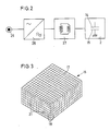
- Fig. 2 the electronic circuit is shown as a block diagram.
- the voltage is transformed by a converter 27 to approximately three kilovolts (KV) from an electrical current source 25, which can be, for example, the public network of 220 volts or a direct current source.
- the frequency required for the converter 27 is generated with a chopper circuit 26. This frequency depends on the ionization area of the first electrode 15 of the ionization part 2 and must be tuned to resonance.
- the converter 27 can be a flow-through, push-pull or resonance converter, the secondary circuit of which is designed as a resonance circuit and is connected with one connection to the first electrode 14 and with the second connection to the protective earth. The frequencies required are approx. 10 kHz.
- the grounding of the second electrode 15 is indicated in the ionization part 2 shown schematically in FIG. 2.
- Fig. 3 the outer appearance of the sterilization device is shown.
- the second electrode 15 with its base surface 17 and the side surfaces 18 is visible.
- the device described fulfills the requirements for trouble-free operation in various rooms, for example in refrigerators and freezers, but also in cars, telephone booths and toilet facilities.
- a size of the device of 90x90x35 mm achieved a secondary power of two watts and a voltage of three KV.
- the isonization area is 49 cm2.
- the ionization surface is essentially the active part of the first electrode 14.
- the electron emission that occurs during operation generates negative ions, in particular oxygen ions. These have the ability to kill bacteria and spores in the air as well as neutralize odors and thus prevent odor transmission, for example smell of onions or cheese on milk or whipped cream.
Landscapes
- Health & Medical Sciences (AREA)
- Animal Behavior & Ethology (AREA)
- Veterinary Medicine (AREA)
- Public Health (AREA)
- General Health & Medical Sciences (AREA)
- Life Sciences & Earth Sciences (AREA)
- Radiology & Medical Imaging (AREA)
- Nuclear Medicine, Radiotherapy & Molecular Imaging (AREA)
- Biomedical Technology (AREA)
- Engineering & Computer Science (AREA)
- Epidemiology (AREA)
- Disinfection, Sterilisation Or Deodorisation Of Air (AREA)
- Apparatus For Disinfection Or Sterilisation (AREA)
- Brushes (AREA)
- Electrostatic Separation (AREA)
- Treating Waste Gases (AREA)
Abstract
Description
- Die Erfindung betrifft ein Gerät zur Entkeimung und Desodorisierung von Räumen, insbesondere von mit Kühl- und Kälteanlagen in Verbindung stehenden Räumen, welches Gerät einen Isolator und zwei am Isolator gegenüberliegende Elektroden aufweist, an welche Hochspannung zur Entstehung einer Koronarentladung angelegt ist.
- Geräte zur Entkeimung von Räumen sind in verschiedenen Ausführungen bekannt. Trotz ihres oft stark verschiedenen Aufbaus erzeugen diese Geräte vor allem Ozon (O₃). Ozon hat eine indirekte, keimtötende Wirkung, jedoch ist Ozon eines der stärksten Oxidationsmittel, welches die Schleimhäute des menschlichen Organismus, insbesondere der Atemwege, angreift und zu lästigen Reizungen führt.
- Für die Erzeugung dieser Luftionisation werden Entladungsröhren verwendet, bei denen an einem Isolator, meistens an einer Glasröhre, an der Innen- und an der Aussenwand je eine Elektrode angelegt wird. An diese beiden gegenüberliegenden Elektroden wird Hochspannung angelegt, die zu Entladungskoronaren mit einer entsprechenden Elektronenemission führen.
- Aus der CH-PS ... ... ist ein Verfahren und eine Vorrichtung zum Erzeugen von Koronarentladungen in Luft bekannt, bei welchen eine Isolatorröhre verwendet wird, in deren Innenraum in der Nähe der Innenwand eine hülsenförmige erste Elektrode angeordnet ist. Eine zweite hülsenförmige Elektrode wird auf die Aussenwand der Isolatorröhre geschoben, welche aus einem Drahtgitter geformt ist und an welcher nach Anlegen einer Hochspannung Koronaren entstehen, welche eine Luftionisation zur Folge hat. Mit diesem Gerät erfolgt die Luftionisation in Form von Sauerstoff-Cluster, deren Verträglichkeit grösser ist als von Ozon (O₃).
- Da jedoch die Isolatorröhre und der dazu gehörende Transformator mit seiner Steuerung ein verhältnismässig grosses Volumen aufweist, sind Geräte dieser Art in kleineren Räumen, wie sie etwa bei Kühlschränken vorliegen, nicht anwendbar, im übrigen auch deshalb nicht, weil bei der benötigten Hochspannung ein amtlich vorgeschriebener Berührungsschutz verlangt wird. Die bekannte Vorrichtung ist deshalb in einem Gehäuse angeordnet und dient der Luftdesinfektion, der Desodorisierung und der Aufbereitung von verbrauchter Luft in grösseren Räumen.
- Die Erfindung liegt ebenfalls im Gebiet der Verbesserung der Luft durch Desinfektion, Desodorisierung und der Aufbereitung durch Ionisation der Luft. Der Erfindung liegt die Aufgabe zugrunde, ein Gerät der eingangs beschriebenen Art so weiterauszugestalten, dass es als kleines, kompaktes Gerät mit einem einwandfreien Berührungsschutz und zudem gegen Temperatur und Feuchtigkeitseinflüsse geschützt ist.
- Diese Aufgabe wird gemäss der Erfindung dadurch gelöst, dass der Isolator, die beiden Elektroden und die Schaltung zur Erzeugung von Hochspannung und Hochfrequenz in Schichtbauweise angeordnet sind.
- Zweckmässig ist hierbei mindestens die Schaltung in einer Vergussmasse, z.B. aus einem Kunststoff, eingebettet. Hierbei weist das Gerät vorzugsweise eine Quaderform auf, innerhalb welcher die Schaltung, die Elektroden und der Isolator angeordnet sind, wobei die Wände des Gerätes durch die an der Masse liegende Elektrode gebildet sind.
- Die Erfindung ist in der Zeichnung in einem Ausführungsbeispiel dargestellt und nachfolgend beschrieben. Es zeigen:
- Fig. 1 ein schematisch dargestelltes Gerät, dessen Teile in auseinandergezogener Lage und in räumlicher Darstellung ersichtlich sind,
- Fig. 2 ein Blockdiagramm der Schaltung des Gerätes nach Fig. 1 und
- Fig. 3 eine Ansicht des Gerätes nach Fig. 1 in räumlicher Darstellung.
- Die Erfindung geht von der Ueberlegung aus, dass ein Gerät zur Entkeimung von Räumen, in denen extreme Verhältnisse bezüglich Temperatur und Feuchtigkeit herrschen, zuverlässig betrieben werden kann, wenn alle empfindlichen Teile gegenüber den genannten Umweltfaktoren geschützt sind und andererseits die offiziellen Vorschriften über den Berührungsschutz erfüllt werden können. Im weiteren soll das Gerät eine möglichst kleine Ausdehnung aufweisen, damit es in dem zu entkeimenden Raum möglichst wenig Platz einnimmt.
- Ein solchen Gerät ist in Fig. 1 dargestellt. Es setzt sich im wesentlichen aus einem Schaltungsteil 1 und einem Ionisationsteil 2 zusammen. Der Schaltungsteil 1 und der Ionisationsteil 2 sind zusammen als quaderförmiger Körper geformt und weisen Dimensionen von weniger als 10 cm in der Länge und Breite sowie weniger als 4 cm in der Höhe auf.
- Aus Fig. 1 sind die einzelnen, schichtweise übereinanderliegenden Teile der Schaltung zu erkennen. Auf einer Grund-Leiterplatte 3 (Grund-Print) ist eine Elektronik-Leiterplatte 4 (Elektronik-Print) angeordnet, welche sämtliche elektronischen Komponenten enthält, die für den Betrieb des Ionisationsteils 2 erforderlich sind Die Elektronik-Leiterplatte 4 kann auch in die Grundleiterplatte 3 integriert sein, so dass dann nur eine Leiterplatte benötigt wird.
- An zwei Halterplatten 5, 6 ist ein Transformator 7 befestigt, an dessen beiden Schenkeln 9 Wicklungen 10, 11 angeordnet sind, wobei die Primärwicklung 10 auf dem einen Schenkel und die Sekundärwicklung auf dem anderen Schenkel angeordnet ist.
- Auf der Grund-Leiterplatte 3 sind Montagebügel 12 abgestützt, mit Hilfe welcher das Entkeimungsgerät auf einer Unterlage befestigt werden kann. Die Montagebügel 12 sind auf zwei Seiten der Grund-Leiterplatte 4 angeordnet, jedoch könnten Sie auch in anderer Weise angeordnet sein. Zweckmässig liegen sie innerhalb der Fläche der Grund-Leiterplatte 3. Die Montagebügel 12 können auch als Teile einer vollen Wand ausgebildet sein.
- Auf der dem Transformator 7 entgegengesetzten Seite der Grund-Leiterplatte 3 ist eine erste Elektrode 14 des Ionisationsteils 2 angeordnet. Die erste Elektrode 14 ist eine massive oder gelochte ebene Platte aus einem Metall, vorzugsweise der Gruppe Stahl, Kupfer, Aluminium und Messing. Die erste Elektrode 14 kann aber auch als Film auf die Oberfläche der Vergussmasse aufgedampft werden.
- Auf der ersten Elektrode 14 ist eine Isolatorplatte 16 gelegt, die aus einem Isolationsmaterial, beispielsweise Glas oder einem Kunststoff, hergestellt ist. Wie aus Fig. 1 ersichtlich ist, weist diese Isolatorplatte 16 etwas grössere Dimensionen als die erste Elektrode 14 auf und überragt somit die erste Elektrode 14 auf ihrem gesamten Umfang.
- Während die erste Elektrode 14 aus einem verhältnismässig dünnen Blech oder Film hergestellt ist, weist die Isolatorplatte 16 eine grössere Dicke auf, beispielsweise 0,5 - 4, 0 mm auf.
- Auf die Isolatorplatte 16 ist eine zweite Elektrode 15 aufgesetzt. Diese ist aus einem Metall, vorzugsweise der Gruppe Stahl, Kupfer, Aluminium, Messing, hergestellt, ist jedoch aus Drähten der genannten Metalle zusammengesetzt und bildet ein Sieb oder Gitter, an dessen Maschen beim Betrieb des Gerätes Elektronen emittiert werden und bei der Verbindung mit Sauerstoff-Atomen negative Sauerstoff-Ionen bilden.
- Die zweite Elektrode 15 setzt sich aus einer ebenen Grundfläche 17 und Seitenflächen 18 zusammen. Die zweite Elektrode 15 bildet somit eine Haube, welche nicht nur den Ionisationsteil 2, sondern auch den Schaltungsteil 1 abdeckt, siehe Fig. 3. Damit die zweite Elektrode 15 nicht durch eine Flüssigkeit oder ein anderes Material verschmutzt wird, kann die zweite Elektrode 15 durch einen Schutzkorb abgedeckt werden, welcher Durchbrechungen aufweist, damit die Elektronenemission in die Luft nicht behindert wird.
- Damit der Schaltungsteil 1 vollständig geschützt ist, wird er vollständig ausgegossen, wozu eine Ausgussmasse 20 verwendet wird. Diese ist ein thermoplastischer oder duroplastischer Kunststoff, der nach dem Vergiessen aushärtet. Die Ausgussmasse 20 erstreckt sich bis zu den Montagebügeln 12 bzw. der Ummantelung 12, die zwar teilweise in der Ausgussmasse eingebettet sind, jedoch soweit zugänglich sind, dass die zweite Elektrode 15 mit den Montagebügeln 12 bzw. der Wand verbunden werden kann, wozu Bohrungen oder Gewindelöcher 21, 22 vorgesehen sind, mit Hilfe welcher die Befestigung der zweiten Elektrode 15 mit den Montagebügeln 12 bzw. der Wand erfolgen kann. Die Montagebügel 12 bzw. die Wand sind an ihrem freien Ende abgewinkelt und weisen dort eine Bohrung 23 auf. Mit diesen Bohrungen kann das zu einem Würfel vergossene Gerät auf einer Unterlage befestigt werden, wobei diese Bolzen und damit auch die zweite Elektrode 15 geerdet sind, so dass damit die amtliche Vorschrift über den Berührungschutz erfüllt ist. Die Grund-Leiterplatte 3 kann auch beidseitig von der Ausgussmasse 20 umgeben sein.
- In Fig. 2 ist die elektronische Schaltung als Blockschema dargestellt. Von einer elektrischen Stromquelle 25, welche beispielsweise das öffentliche Netz von 220 Volt oder eine Gleichstromquelle sein kann, wird die Spannung mit einem Wandler 27 auf etwa drei Kilovolt (KV) transformiert. Mit einer Zerhackerschaltung 26 wird die für den Wandler 27 erforderliche Frequenz erzeugt. Diese Frequenz ist von der lonisationsfläche der ersten Elektrode 15 des Ionisationsteiles 2 abhängig und muss auf Resonanz abgestimmt werden. Der Wandler 27 kann hierbei ein Durchfluss-, Gegentakt- oder Resonanz-Wandler sein, dessen Sekundärkreis als Resonanzkreis ausgebildet ist und mit einem Anschluss mit der ersten Elektrode 14 und mit dem zweiten Anschluss mit der Schutzerde verbunden ist. Die benötigten Frequenzen betragen ca. 10 Khz. In dem in Fig. 2 schematisch dargestellten Ionisationsteil 2 ist die Erdung der zweiten Elektrode 15 angedeutet.
- In Fig. 3 ist das äussere Aussehen des Entkeimungsgerätes dargestellt. Sichtbar ist die zweite Elektrode 15 mit ihrer Grundfläche 17 und den Seitenflächen 18.
- Das beschriebene Gerät erfüllt die Voraussetzungen eines störungsfreien Betriebes in verschiedenen Räumen, z.B. in Kühl- und Gefrierräumen, aber auch in Autos, Telefonkabinen und WC-Anlagen. Bei einer Grösse des Gerätes von 90x90x35 mm wird eine Sekundärleistung von zwei Watt und eine Spannung von drei KV erreicht. Die Isonisationsfläche beträgt hierbei 49 cm². Die Ionisationsfläche ist im wesentlichen der aktive Teil der ersten Elektrode 14. Die im Betrieb auftretende Elektronenemission erzeugt negative Ionen, insbesondere Sauerstoff-Ionen. Diese haben die Fähigkeit, Bakterien und Sporen in der Luft abzutöten sowie Gerüche zu neutralisieren und damit Geruchübertragungen zu verhindern, z.B. Zwiebel- oder Käsegeruch auf Milch oder Schlagrahm.
Claims (8)
Applications Claiming Priority (2)
| Application Number | Priority Date | Filing Date | Title |
|---|---|---|---|
| CH2163/88 | 1988-06-07 | ||
| CH2163/88A CH677400A5 (de) | 1988-06-07 | 1988-06-07 |
Publications (2)
| Publication Number | Publication Date |
|---|---|
| EP0345498A1 true EP0345498A1 (de) | 1989-12-13 |
| EP0345498B1 EP0345498B1 (de) | 1995-03-15 |
Family
ID=4227349
Family Applications (1)
| Application Number | Title | Priority Date | Filing Date |
|---|---|---|---|
| EP89108929A Expired - Lifetime EP0345498B1 (de) | 1988-06-07 | 1989-05-18 | Gerät zur Entkeimung und Desodorisierung von Räumen |
Country Status (9)
| Country | Link |
|---|---|
| US (1) | US5136461A (de) |
| EP (1) | EP0345498B1 (de) |
| KR (1) | KR970011446B1 (de) |
| AT (1) | ATE120045T1 (de) |
| CA (1) | CA1331476C (de) |
| CH (1) | CH677400A5 (de) |
| DE (1) | DE58909105D1 (de) |
| HK (1) | HK79096A (de) |
| ZA (1) | ZA894108B (de) |
Cited By (4)
| Publication number | Priority date | Publication date | Assignee | Title |
|---|---|---|---|---|
| WO1994007359A1 (en) * | 1992-09-29 | 1994-04-14 | Ferplast Spa | Container for domestic animals provided with air purifying/ionising device |
| AT407296B (de) * | 1998-06-16 | 2001-02-26 | Ingo Ing Kohlhauser | Luftionisator |
| WO2003028179A1 (en) * | 2001-08-01 | 2003-04-03 | Sharp Kabushiki Kaisha | Ion generator, and electric apparatus and air conditioning apparatus incorporating the same |
| DE19931662B4 (de) * | 1998-07-08 | 2005-05-04 | Dieckmann, Bastian | Vorrichtung zur Erzeugung ionisierter Gase mittels Korona-Entladungen |
Families Citing this family (41)
| Publication number | Priority date | Publication date | Assignee | Title |
|---|---|---|---|---|
| JP2637693B2 (ja) * | 1994-04-05 | 1997-08-06 | 三星電子株式会社 | 冷蔵庫の多機能付加装置 |
| US5480615A (en) * | 1994-12-12 | 1996-01-02 | Curry; Jeanette | Germicide diffuser |
| DE19651402A1 (de) * | 1996-12-11 | 1998-06-18 | T E M Tech Entwicklung Und Man | Apparat zur physikalischen Aufbereitung von Luft, insbesondere von Atemluft |
| US6565805B2 (en) | 1997-10-23 | 2003-05-20 | Hartz International Inc. | Ozone generator for deodorizing shoes |
| US6504308B1 (en) * | 1998-10-16 | 2003-01-07 | Kronos Air Technologies, Inc. | Electrostatic fluid accelerator |
| US6176977B1 (en) | 1998-11-05 | 2001-01-23 | Sharper Image Corporation | Electro-kinetic air transporter-conditioner |
| US7695690B2 (en) | 1998-11-05 | 2010-04-13 | Tessera, Inc. | Air treatment apparatus having multiple downstream electrodes |
| US7220295B2 (en) | 2003-05-14 | 2007-05-22 | Sharper Image Corporation | Electrode self-cleaning mechanisms with anti-arc guard for electro-kinetic air transporter-conditioner devices |
| US6544485B1 (en) | 2001-01-29 | 2003-04-08 | Sharper Image Corporation | Electro-kinetic device with enhanced anti-microorganism capability |
| US20030206837A1 (en) | 1998-11-05 | 2003-11-06 | Taylor Charles E. | Electro-kinetic air transporter and conditioner device with enhanced maintenance features and enhanced anti-microorganism capability |
| US7318856B2 (en) | 1998-11-05 | 2008-01-15 | Sharper Image Corporation | Air treatment apparatus having an electrode extending along an axis which is substantially perpendicular to an air flow path |
| US20050210902A1 (en) | 2004-02-18 | 2005-09-29 | Sharper Image Corporation | Electro-kinetic air transporter and/or conditioner devices with features for cleaning emitter electrodes |
| EP1293216A4 (de) | 2000-05-18 | 2003-08-20 | Sharp Kk | Verfahren zur sterilisation, ionenerzeugendes element, ionen erzeugende vorrichtung und klimaanlage |
| US6752970B2 (en) * | 2001-08-14 | 2004-06-22 | Shaklee Corporation | Air treatment apparatus and methods |
| US6668563B2 (en) * | 2002-02-09 | 2003-12-30 | Bernard J. Mirowsky | Air treatment system for airplanes |
| US6727657B2 (en) * | 2002-07-03 | 2004-04-27 | Kronos Advanced Technologies, Inc. | Electrostatic fluid accelerator for and a method of controlling fluid flow |
| US6963479B2 (en) | 2002-06-21 | 2005-11-08 | Kronos Advanced Technologies, Inc. | Method of and apparatus for electrostatic fluid acceleration control of a fluid flow |
| US6919698B2 (en) * | 2003-01-28 | 2005-07-19 | Kronos Advanced Technologies, Inc. | Electrostatic fluid accelerator for and method of controlling a fluid flow |
| US6937455B2 (en) | 2002-07-03 | 2005-08-30 | Kronos Advanced Technologies, Inc. | Spark management method and device |
| US7122070B1 (en) | 2002-06-21 | 2006-10-17 | Kronos Advanced Technologies, Inc. | Method of and apparatus for electrostatic fluid acceleration control of a fluid flow |
| US7150780B2 (en) | 2004-01-08 | 2006-12-19 | Kronos Advanced Technology, Inc. | Electrostatic air cleaning device |
| US7053565B2 (en) | 2002-07-03 | 2006-05-30 | Kronos Advanced Technologies, Inc. | Electrostatic fluid accelerator for and a method of controlling fluid flow |
| US7157704B2 (en) | 2003-12-02 | 2007-01-02 | Kronos Advanced Technologies, Inc. | Corona discharge electrode and method of operating the same |
| US7405672B2 (en) | 2003-04-09 | 2008-07-29 | Sharper Image Corp. | Air treatment device having a sensor |
| US20050051420A1 (en) | 2003-09-05 | 2005-03-10 | Sharper Image Corporation | Electro-kinetic air transporter and conditioner devices with insulated driver electrodes |
| US7724492B2 (en) | 2003-09-05 | 2010-05-25 | Tessera, Inc. | Emitter electrode having a strip shape |
| US7077890B2 (en) | 2003-09-05 | 2006-07-18 | Sharper Image Corporation | Electrostatic precipitators with insulated driver electrodes |
| US7517503B2 (en) | 2004-03-02 | 2009-04-14 | Sharper Image Acquisition Llc | Electro-kinetic air transporter and conditioner devices including pin-ring electrode configurations with driver electrode |
| US7906080B1 (en) | 2003-09-05 | 2011-03-15 | Sharper Image Acquisition Llc | Air treatment apparatus having a liquid holder and a bipolar ionization device |
| US7767169B2 (en) | 2003-12-11 | 2010-08-03 | Sharper Image Acquisition Llc | Electro-kinetic air transporter-conditioner system and method to oxidize volatile organic compounds |
| US7638104B2 (en) | 2004-03-02 | 2009-12-29 | Sharper Image Acquisition Llc | Air conditioner device including pin-ring electrode configurations with driver electrode |
| US20060016333A1 (en) | 2004-07-23 | 2006-01-26 | Sharper Image Corporation | Air conditioner device with removable driver electrodes |
| US7285155B2 (en) | 2004-07-23 | 2007-10-23 | Taylor Charles E | Air conditioner device with enhanced ion output production features |
| US7311762B2 (en) | 2004-07-23 | 2007-12-25 | Sharper Image Corporation | Air conditioner device with a removable driver electrode |
| US7410532B2 (en) | 2005-04-04 | 2008-08-12 | Krichtafovitch Igor A | Method of controlling a fluid flow |
| CN100360189C (zh) * | 2005-12-20 | 2008-01-09 | 仇剑梅 | 离子捕捉型广谱高效动态快速空气消毒净化机 |
| WO2007085113A1 (fr) * | 2006-01-24 | 2007-08-02 | Shanghai Air Clean Systems Engineering Co., Ltd. | Tube de génération d'ions oxygène |
| US7833322B2 (en) | 2006-02-28 | 2010-11-16 | Sharper Image Acquisition Llc | Air treatment apparatus having a voltage control device responsive to current sensing |
| DE102006033612B3 (de) * | 2006-07-18 | 2007-09-27 | Universität Bremen | Ionisationsvorrichtung zur Gasionisierung, sowie Vorrichtungen und Verfahren zum Aufbereiten von verunreinigtem Wasser |
| WO2010074654A1 (en) * | 2008-12-23 | 2010-07-01 | Oxion Pte. Ltd. | Air ionizer electrode assembly |
| US12239999B1 (en) * | 2020-11-24 | 2025-03-04 | Aqmc Llc | Air quality control |
Citations (4)
| Publication number | Priority date | Publication date | Assignee | Title |
|---|---|---|---|---|
| DE2064690A1 (de) * | 1970-12-31 | 1972-07-27 | Hildebrand A | Bioklimagerät |
| DE2413275A1 (de) * | 1973-03-20 | 1974-09-26 | Wilhelm Van Den Berg | Verfahren zur erzeugung von ionen und ionengenerator zur ausuebung desselben |
| EP0053647A1 (de) * | 1980-12-06 | 1982-06-16 | Baumgartner, Reinhard, Dipl.-Wirtsch.-Ing., Dipl.-Kaufm. | Impulsfelderzeugendes Kompaktgerät |
| DE3106187A1 (de) * | 1981-02-19 | 1982-09-09 | Static Inc., 01238 Lee, Mass. | Duennschichtionisator und verfahren zu seiner herstellung |
Family Cites Families (6)
| Publication number | Priority date | Publication date | Assignee | Title |
|---|---|---|---|---|
| US4096544A (en) * | 1976-12-09 | 1978-06-20 | Vladimir Ignatjev | Air ionizer |
| US4496375A (en) * | 1981-07-13 | 1985-01-29 | Vantine Allan D Le | An electrostatic air cleaning device having ionization apparatus which causes the air to flow therethrough |
| JPS6059104B2 (ja) * | 1982-02-03 | 1985-12-23 | 株式会社東芝 | 静電チヤツク板 |
| US4533598A (en) * | 1983-11-18 | 1985-08-06 | Caschem, Inc. | Extended polyurethanes |
| US4589053A (en) * | 1984-06-07 | 1986-05-13 | Canon Kabushiki Kaisha | Method and device for charging or discharging a member |
| US4792680A (en) * | 1987-01-12 | 1988-12-20 | Xerox Corporation | Corona device having a beryllium copper screen |
-
1988
- 1988-06-07 CH CH2163/88A patent/CH677400A5/de not_active IP Right Cessation
-
1989
- 1989-05-18 EP EP89108929A patent/EP0345498B1/de not_active Expired - Lifetime
- 1989-05-18 AT AT89108929T patent/ATE120045T1/de not_active IP Right Cessation
- 1989-05-18 DE DE58909105T patent/DE58909105D1/de not_active Expired - Fee Related
- 1989-05-30 ZA ZA894108A patent/ZA894108B/xx unknown
- 1989-06-05 KR KR1019890007757A patent/KR970011446B1/ko not_active Expired - Fee Related
- 1989-06-06 CA CA000601923A patent/CA1331476C/en not_active Expired - Fee Related
- 1989-06-07 US US07/362,359 patent/US5136461A/en not_active Expired - Lifetime
-
1996
- 1996-05-02 HK HK79096A patent/HK79096A/xx not_active IP Right Cessation
Patent Citations (4)
| Publication number | Priority date | Publication date | Assignee | Title |
|---|---|---|---|---|
| DE2064690A1 (de) * | 1970-12-31 | 1972-07-27 | Hildebrand A | Bioklimagerät |
| DE2413275A1 (de) * | 1973-03-20 | 1974-09-26 | Wilhelm Van Den Berg | Verfahren zur erzeugung von ionen und ionengenerator zur ausuebung desselben |
| EP0053647A1 (de) * | 1980-12-06 | 1982-06-16 | Baumgartner, Reinhard, Dipl.-Wirtsch.-Ing., Dipl.-Kaufm. | Impulsfelderzeugendes Kompaktgerät |
| DE3106187A1 (de) * | 1981-02-19 | 1982-09-09 | Static Inc., 01238 Lee, Mass. | Duennschichtionisator und verfahren zu seiner herstellung |
Cited By (5)
| Publication number | Priority date | Publication date | Assignee | Title |
|---|---|---|---|---|
| WO1994007359A1 (en) * | 1992-09-29 | 1994-04-14 | Ferplast Spa | Container for domestic animals provided with air purifying/ionising device |
| AT407296B (de) * | 1998-06-16 | 2001-02-26 | Ingo Ing Kohlhauser | Luftionisator |
| DE19931662B4 (de) * | 1998-07-08 | 2005-05-04 | Dieckmann, Bastian | Vorrichtung zur Erzeugung ionisierter Gase mittels Korona-Entladungen |
| WO2003028179A1 (en) * | 2001-08-01 | 2003-04-03 | Sharp Kabushiki Kaisha | Ion generator, and electric apparatus and air conditioning apparatus incorporating the same |
| US7256979B2 (en) | 2001-08-01 | 2007-08-14 | Sharp Kabushiki Kaisha | Ion generator, and electric apparatus and air conditioning apparatus incorporating the same |
Also Published As
| Publication number | Publication date |
|---|---|
| ATE120045T1 (de) | 1995-04-15 |
| HK79096A (en) | 1996-05-10 |
| KR970011446B1 (ko) | 1997-07-11 |
| KR900000094A (ko) | 1990-01-30 |
| CA1331476C (en) | 1994-08-16 |
| US5136461A (en) | 1992-08-04 |
| DE58909105D1 (de) | 1995-04-20 |
| EP0345498B1 (de) | 1995-03-15 |
| ZA894108B (en) | 1990-03-28 |
| CH677400A5 (de) | 1991-05-15 |
Similar Documents
| Publication | Publication Date | Title |
|---|---|---|
| EP0345498B1 (de) | Gerät zur Entkeimung und Desodorisierung von Räumen | |
| DE19618771C2 (de) | Wasserentnahmearmatur | |
| DE3208895C2 (de) | Schaltungsanordnung zum impulsförmigen Betreiben von einem oder mehreren Hochfrequenz-Ozonisatoren | |
| DE69404698T2 (de) | Vorrichtung für die Befeuchtung und Ionisation von Luft | |
| DE3204534C2 (de) | Elektromagnetisch betätigte Membranpumpe | |
| EP1666074A1 (de) | Entkeimungsleuchte | |
| EP0329849B1 (de) | Variable Schockwellenenergie durch angepassten ohmschen Verbraucher | |
| DE4103763A1 (de) | Ozonisator | |
| EP0158038A1 (de) | Nebelgenerator | |
| DE4420038A1 (de) | Gerät zum Entkeimen und Desodorieren von Räumen | |
| DE102017002210A1 (de) | Kühlvorrichtung für Röntgengeneratoren | |
| DE102020104533B4 (de) | Fluidbehandlungsvorrichtung, Elektrodengitter dafür und Baueinheit aus einer Mehrzahl solcher Elektrodengitter | |
| EP0647594A2 (de) | Elektrostatische Wassersterilisierapparat | |
| DE102021203211B3 (de) | Vorrichtung für die atmosphärische dielektrische Barriereentladung sowie Herstellungsverfahren dafür | |
| EP0687869A2 (de) | Verfahren und Vorrichtung zum Entwesen von Luft | |
| DE19931662B4 (de) | Vorrichtung zur Erzeugung ionisierter Gase mittels Korona-Entladungen | |
| DE102018119216B4 (de) | Gehäuse für eine elektronische Komponente mit einem Innenbehälter und einer Außenumhüllung | |
| DE3331803A1 (de) | Vorrichtung zur erzeugung eines ueberschusses von negativen ionen in geschlossenen raeumen bzw. einem luftstrom | |
| DE4400503C2 (de) | Elektrochemische Feuchtigkeitssperre | |
| AT235524B (de) | Verfahren zur elektrischen Raumklimatisierung und Einrichtung zur Durchführung des Verfahrens | |
| DE2926123C2 (de) | ||
| DE10308749A1 (de) | Vorrichtung zur Kühlung elektrischer Bauteile | |
| DE3331804A1 (de) | Vorrichtung zur erzeugung von negativen ionen | |
| DE2452824A1 (de) | Luftionisierungsanlage | |
| DE102023117341B3 (de) | Vorrichtung und Verfahren zur kombinierten Luft- und Oberflächendesinfektion |
Legal Events
| Date | Code | Title | Description |
|---|---|---|---|
| PUAI | Public reference made under article 153(3) epc to a published international application that has entered the european phase |
Free format text: ORIGINAL CODE: 0009012 |
|
| AK | Designated contracting states |
Kind code of ref document: A1 Designated state(s): AT BE DE ES FR GB GR IT LU NL SE |
|
| 17P | Request for examination filed |
Effective date: 19900519 |
|
| 17Q | First examination report despatched |
Effective date: 19920907 |
|
| GRAA | (expected) grant |
Free format text: ORIGINAL CODE: 0009210 |
|
| AK | Designated contracting states |
Kind code of ref document: B1 Designated state(s): AT BE DE ES FR GB GR IT LU NL SE |
|
| PG25 | Lapsed in a contracting state [announced via postgrant information from national office to epo] |
Ref country code: IT Free format text: LAPSE BECAUSE OF FAILURE TO SUBMIT A TRANSLATION OF THE DESCRIPTION OR TO PAY THE FEE WITHIN THE PRESCRIBED TIME-LIMIT;WARNING: LAPSES OF ITALIAN PATENTS WITH EFFECTIVE DATE BEFORE 2007 MAY HAVE OCCURRED AT ANY TIME BEFORE 2007. THE CORRECT EFFECTIVE DATE MAY BE DIFFERENT FROM THE ONE RECORDED. Effective date: 19950315 Ref country code: NL Free format text: LAPSE BECAUSE OF FAILURE TO SUBMIT A TRANSLATION OF THE DESCRIPTION OR TO PAY THE FEE WITHIN THE PRESCRIBED TIME-LIMIT Effective date: 19950315 Ref country code: ES Free format text: THE PATENT HAS BEEN ANNULLED BY A DECISION OF A NATIONAL AUTHORITY Effective date: 19950315 Ref country code: GR Free format text: LAPSE BECAUSE OF FAILURE TO SUBMIT A TRANSLATION OF THE DESCRIPTION OR TO PAY THE FEE WITHIN THE PRESCRIBED TIME-LIMIT Effective date: 19950315 |
|
| REF | Corresponds to: |
Ref document number: 120045 Country of ref document: AT Date of ref document: 19950415 Kind code of ref document: T |
|
| ET | Fr: translation filed | ||
| GBT | Gb: translation of ep patent filed (gb section 77(6)(a)/1977) |
Effective date: 19950309 |
|
| REF | Corresponds to: |
Ref document number: 58909105 Country of ref document: DE Date of ref document: 19950420 |
|
| PG25 | Lapsed in a contracting state [announced via postgrant information from national office to epo] |
Ref country code: LU Free format text: LAPSE BECAUSE OF NON-PAYMENT OF DUE FEES Effective date: 19950531 |
|
| PG25 | Lapsed in a contracting state [announced via postgrant information from national office to epo] |
Ref country code: SE Effective date: 19950615 |
|
| NLV1 | Nl: lapsed or annulled due to failure to fulfill the requirements of art. 29p and 29m of the patents act | ||
| PLBE | No opposition filed within time limit |
Free format text: ORIGINAL CODE: 0009261 |
|
| STAA | Information on the status of an ep patent application or granted ep patent |
Free format text: STATUS: NO OPPOSITION FILED WITHIN TIME LIMIT |
|
| 26N | No opposition filed | ||
| REG | Reference to a national code |
Ref country code: GB Ref legal event code: IF02 |
|
| PGFP | Annual fee paid to national office [announced via postgrant information from national office to epo] |
Ref country code: BE Payment date: 20020422 Year of fee payment: 14 |
|
| PGFP | Annual fee paid to national office [announced via postgrant information from national office to epo] |
Ref country code: AT Payment date: 20020506 Year of fee payment: 14 |
|
| PG25 | Lapsed in a contracting state [announced via postgrant information from national office to epo] |
Ref country code: AT Free format text: LAPSE BECAUSE OF NON-PAYMENT OF DUE FEES Effective date: 20030518 |
|
| PG25 | Lapsed in a contracting state [announced via postgrant information from national office to epo] |
Ref country code: BE Free format text: LAPSE BECAUSE OF NON-PAYMENT OF DUE FEES Effective date: 20030531 |
|
| BERE | Be: lapsed |
Owner name: *ZELLWEGER MAX Effective date: 20030531 |
|
| PGFP | Annual fee paid to national office [announced via postgrant information from national office to epo] |
Ref country code: GB Payment date: 20050511 Year of fee payment: 17 |
|
| PGFP | Annual fee paid to national office [announced via postgrant information from national office to epo] |
Ref country code: FR Payment date: 20050530 Year of fee payment: 17 |
|
| PGFP | Annual fee paid to national office [announced via postgrant information from national office to epo] |
Ref country code: DE Payment date: 20050727 Year of fee payment: 17 |
|
| PG25 | Lapsed in a contracting state [announced via postgrant information from national office to epo] |
Ref country code: GB Free format text: LAPSE BECAUSE OF NON-PAYMENT OF DUE FEES Effective date: 20060518 |
|
| PG25 | Lapsed in a contracting state [announced via postgrant information from national office to epo] |
Ref country code: DE Free format text: LAPSE BECAUSE OF NON-PAYMENT OF DUE FEES Effective date: 20061201 |
|
| GBPC | Gb: european patent ceased through non-payment of renewal fee |
Effective date: 20060518 |
|
| REG | Reference to a national code |
Ref country code: FR Ref legal event code: ST Effective date: 20070131 |
|
| PG25 | Lapsed in a contracting state [announced via postgrant information from national office to epo] |
Ref country code: FR Free format text: LAPSE BECAUSE OF NON-PAYMENT OF DUE FEES Effective date: 20060531 |