EP0345516A2 - Centrifugeuse pour la séparation de mélanges de fluides et de particules solides - Google Patents
Centrifugeuse pour la séparation de mélanges de fluides et de particules solides Download PDFInfo
- Publication number
- EP0345516A2 EP0345516A2 EP89109134A EP89109134A EP0345516A2 EP 0345516 A2 EP0345516 A2 EP 0345516A2 EP 89109134 A EP89109134 A EP 89109134A EP 89109134 A EP89109134 A EP 89109134A EP 0345516 A2 EP0345516 A2 EP 0345516A2
- Authority
- EP
- European Patent Office
- Prior art keywords
- centrifuge
- centrifuge according
- ring part
- centrifugal drum
- sieve
- Prior art date
- Legal status (The legal status is an assumption and is not a legal conclusion. Google has not performed a legal analysis and makes no representation as to the accuracy of the status listed.)
- Granted
Links
Images

Classifications
-
- B—PERFORMING OPERATIONS; TRANSPORTING
- B04—CENTRIFUGAL APPARATUS OR MACHINES FOR CARRYING-OUT PHYSICAL OR CHEMICAL PROCESSES
- B04B—CENTRIFUGES
- B04B3/00—Centrifuges with rotary bowls in which solid particles or bodies become separated by centrifugal force and simultaneous sifting or filtering
Definitions
- the invention relates to a centrifuge for separating mixtures of liquids and solid particles, in particular plastic granules, with a centrifugal drum which widens towards its upper end which serves to discharge the particles and which comprises a sieve part and a baffle ring part, the baffle ring part adjacent to the discharge end and the Sieve part are arranged adjacent to the lower end of the centrifugal drum, with a drive device and with a feed device for the mixtures.
- centrifuges also called baffle ring centrifuges
- baffle ring centrifuges are known for example from DE-PS 24 59 796, in which the mixtures of liquids and solid particles are placed in the lower, tapered area of the centrifugal drum, the mixtures initially being subjected to a rough separation in the sieve section and then undergo another separation process in the baffle ring part.
- impact ring Centrifuges the centrifugal drum is stored and driven on its lower end. The mixtures are supplied from above via a pipeline which extends essentially into the sieve part at the lower end of the centrifugal drum.
- the object of the invention is to simplify the construction of the centrifuge and to make it more economical to load the centrifuge.
- the hanging storage of the centrifugal drum also simplifies the construction and it can be provided that the centrifugal drum, together with the drive, can be removed from the centrifuge can be taken so that the centrifuge together with the centrifuge housing can be cleaned very easily and completely when changing the type of granulate to be processed.
- the drive motor is preferably arranged on a cover located on the top of the centrifuge.
- the centrifugal drum is expediently mounted on the drive shaft.
- the drive shaft can be connected to the motor shaft of the drive device via a coupling or can be formed in one piece with the motor shaft. In the latter case, the bearing of the motor shaft is used to support the centrifugal drum.
- the drive shaft projects into the interior of the centrifugal drum and carries an annular flange to which the sieve part and the impact ring part of the centrifugal drum can be fastened.
- a ring part is attached to the ring flange for mounting the sieve part and the impact ring part.
- the embodiments in which the sieve part and the impact ring part are arranged on opposite sides of the ring part and can be fixed thereon with common fastening elements are advantageous here.
- the complete centrifugal drum can be removed from the centrifuge housing, serviced and cleaned together with the drive device.
- the ring part is held on the ring flange by means of radially extending webs, the spaces between the webs forming passage channels which connect the centrifuge space of the sieve part with the centrifuge space of the impact ring part.
- the webs can be designed so that they accelerate the solid particles entering the passage channels from the sieve part in the circumferential direction of the centrifugal drum via a driving device.
- the difference in the peripheral speed between the solid particles and the baffle ring surface on which the particle strikes is significantly reduced, so that a much gentler treatment of the solid particles in the centrifuge is achieved.
- the webs can also be designed as air compressor blades that maintain a pressure drop between the screen section and the impact ring section. Since the wetted sieve surface of the sieve part prevents air from entering the centrifuge space outside the centrifugal drum, this slight negative pressure in the sieve part can support the introduction of the solid / liquid mixture.
- This effect is particularly pronounced when the ring flange on the drive shaft essentially completely separates the centrifuge space of the sieve part from that of the baffle ring part, so that there is a connection between these subspaces in the centrifuge only via the passage channels between the webs.
- This embodiment has the additional advantage that no splash water can get from the sieve part into the baffle ring part of the centrifuge, as a result of which the material to be dried would be moistened again.
- the baffle ring part of the centrifuge is advantageously equipped with baffles which prevent the solid particles from jumping up and ensure that they pass through all stages of the baffle ring part.
- the baffles can also contribute to the acceleration of the particles in the circumferential direction of the centrifuge, so that a treatment of the particles which is as gentle as possible, that is to say generates as little abrasion as possible, is also realized in the impact ring part.
- the noise generated by the centrifuge can be significantly reduced if the impact rings are made as solid parts.
- the reduction of the noise level serves both the use of solid cast parts and / or those made from mechanically processed, solid materials.
- the drive device comprises a drive motor cooled by means of an air flow, the air flow coming from the drive motor being able to be fed to the discharge end of the centrifugal drum via feed lines.
- the centrifugal drum and / or the drive device carry air compressor blades.
- These air compressor blades which lead to a suction of the ambient and / or the cooling air of the engine are, of course, also useful without the provision of a pneumatic conveying path for the solid particles in connection with the centrifuge according to the invention, since they generate an overpressure in the area of the discharge channel, which causes the transfer of Moist air from the lower part of the housing is prevented by the annular gap between the upper part of the centrifugal drum and the seal.
- the supply device When the mixtures of liquids and solid particles can be supplied from below according to the invention, it is advisable to provide the supply device with a siphon tube, the riser tube of which is arranged adjacent to the lower end of the centrifugal drum.
- the arrangement of a siphon tube in the feed device has the advantage that fluctuations in the volume flow of the mixture through the siphon tube are automatically compensated.
- the siphon tube is preferably part of a thickening and / or metering device by means of which excess liquid portions of the mixture can be separated beforehand, so that only those liquid portions which are necessary for further cooling and especially for the transport of the solid particles are fed to the centrifuge .
- the riser pipe should always have a smaller height than the down pipe of the siphon.
- the siphon tube on the centrifuge or the siphon tube parts are connected to one another with quick-release fasteners.
- the centrifuge with its feed device becomes particularly interference-free for a certain type of granulate if the height difference of the inlet and outlet side of the siphon and the cross sections of the riser are matched to one another in such a way that the flow rate of the mixture in the riser is greater than or equal to the sinking speed of the solid particles contained in the mixture.
- the volume flow of the mixture can be adapted to the absorption capacity of the centrifugal drum.
- the absorption capacity of the centrifugal drum can be different for different solid / liquid mixtures, since depending on the density of the solid particles, different ratios of solid particles and liquid are necessary for maintaining trouble-free transport conditions.
- optimal operating conditions will be achieved, for example, with a weight ratio of 1: 1.
- the signal from the measuring probe can be evaluated on the one hand in the event that in the event of a lack of liquid, additional liquid components are added to the mixture via a feed line, so that stable transport conditions for the solid particles result again, or that in the event of an undesired increase in the liquid level beyond the intended maximum an alarm signal is generated which draws the operator's attention to the malfunction.
- baffle ring centrifuge which comprises a suspended rotor which has a baffle ring part and a sieve part, each of which is individually detachably attached to a disk, since here too the mixtures are fed in via the hanging bearing of the rotor below and due to the easy disassembly of the impact ring part and sieve part, easy cleaning and maintenance of the centrifuge is possible.
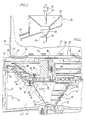
- FIG. 1 shows a schematic view of a centrifuge 10 according to the invention in a housing 12, to which a lateral chamber 14 is attached, which receives a feed device 16 in the form of a thickening and / or metering device.
- Fig. 1 shows the essential features of a centrifuge 10 constructed according to the invention, namely a hanging rotor or a centrifugal drum 18, which has an opening 20 at its lower end through which the feed device 16 extends with a riser pipe 22 of its siphon 24.
- the rotor 18 is suspended from a drive device 26, which extends with its drive shaft 28 into the interior of the housing 12 of the centrifuge 10.
- the centrifugal drum 18 is fastened via a ring part 30, which forms the discharge end of the centrifugal drum, to a circular plate 32 which has a sleeve 34 in the center, which is pushed over the drive shaft 28 and connected to it in a rotationally fixed manner.
- the drive device 26 comprises a drive motor 27 which is flanged onto a cover 13 of the housing 12, the drive shaft 28 protruding through the cover 13 into the interior of the centrifuge 10.
- a discharge channel 40 is flanged, which is tangential to the centrifugal drum 18 in its longitudinal direction. The liquid portions are separated off via the discharge channel 40 Removed th solid particles from the centrifuge 12.
- the lid 13 is fastened to the surface of the housing 12 with hand screws 42 and can be removed from the housing 12 of the centrifuge 10 together with the drive device 26 and the rotor or centrifugal drum 18 fastened thereon.
- the chamber 42 is connected to the side chamber 14 via an opening 46 so that the liquid components occurring in both chambers can flow off via a common drain 48.
- the feed device 16 essentially consists of an inlet area or inlet box 50 which has a lateral inlet opening 51. The outlet opening of a granulator preceding in the production process can be flanged to this inlet opening 51, for example.
- the inlet box 50 comprises a sieve plate 53 standing vertically on its base plate 52, which is bent in a U-shape and points with its opening to the inlet opening 51.
- a weir 54 is attached to the lower end of the sieve plate 53 and defines a minimum liquid level in the inlet box 50.
- the bottom plate 52 of the inlet box 50 has an inlet funnel 56 which opens into the downpipe 25 of the siphon 24.
- the partial pipe 23 is held in the area of the two elbows with quick-release fasteners 55 at the respective lower ends of the riser pipe 22 and down pipe 25.
- this division of the siphon 24 into a down pipe 25, a riser pipe 22 and a horizontally extending partial pipe 23 with the possibility of attaching the partial pipe 23 in any orientation to the lower ends of the down pipe and riser pipe via quick-release fasteners 55, contributes significantly to the ease of maintenance of the System, since here the curved supply areas of the feed device 16 are very easily accessible for thorough cleaning.
- FIG 3 shows a variant of the inlet box 50 to the version shown in FIGS. 1 and 2.
- a downwardly tapering sieve plate 58 is used, which is used above all in mixtures with very high excesses of water or liquid.
- part of the liquid is withdrawn from the mixture right from the start and not only in special cases when excess water is also present, as is the case with the device according to FIGS. 1 and 2.
- the sieve bottom 58 opens with its tapered end into an inlet funnel 59, which is configured similarly to the inlet funnel 56 in FIGS. 1 and 2.
- a measuring probe 60 is arranged on the down pipe 25 adjoining the inlet funnel 59, by means of which the filling level on the down pipe side of the feed device 16 can be measured.
- the signal from the measuring probe can be used, on the one hand, to activate a supply line 62 and its valve 63 when the liquid content is too low, so that additional liquid parts are added to the inflowing mixture or also to detect an operating fault, namely when the liquid level is above the Downpipe 25 rises too much, for example due to clogging of the sieve plate 58, which requires the intervention of operating personnel.
- the signal from the measuring probe is used to trigger a warning tone or an alarm transmitter.
- the inlet box 50 of the version shown in FIG. 3 has a separate outlet 64 for the liquid components separated by the sieve bottom 58, since larger quantities of liquid are already produced in this part of the device.
- Fig. 4 shows a more detailed structure of a centrifuge according to the invention, in particular the structure of the centrifugal drum 18 '.
- the structure of the centrifuge shown in Fig. 4 differs in principle from that shown in Fig. 1, as the centrifugal drum 18 'is held on the ring flange 79 or on the welded to this via webs 80 connecting ring or ring member 70.
- the centrifugal drum 18 ' is composed of a sieve part 68, a baffle ring part 69 and the connecting ring 70, which is arranged at the junction of the sieve part 68 and baffle ring part 69 and offers a common mounting option for both parts of the centrifugal drum.
- the sieve part 68 tapers towards its lower end to a diameter which corresponds to the diameter of the riser pipe 22 and ends just above this riser pipe.
- the sieve part 68 is reinforced by circumferential ribs 72 and serves to roughly separate solid particles and liquid, which is already thrown out into the space 42 to a large extent through the openings in the sieve part.
- annular flange 73 is arranged, with which the sieve part 68 is held in a circumferential recess 74 of a lower opening of the impact ring part 69.
- the impact ring part 69 has at its lower open end an inwardly facing ring flange 75, on which the connecting ring 70 can be placed, which overlaps with the flange 73 of the sieve part 68 and thus the sieve part 68 with its flange 73 against the recess 74 in Presses ring flange 75 of the impact ring part.
- the three parts of the centrifugal drum 18 ', namely the sieve part 68, the impact ring part 69 and the connecting ring 70 are held together by common screw connections 76, so that the solution of these screw connections is sufficient to separate all three parts from one another.
- the webs between the connecting ring or ring part 70 form with their gaps radially extending through channels 100. Since the ring flange 79 ensures a strict separation of the interior of the baffle ring part 69, the through channels 100 form the only connection between these volumes. This avoids the transfer of splash water from the sieve part 68 into the baffle ring part 69 and an inevitable rewetting of the already dried solid particles.
- the discharge channel 40 is separated from the lower volume 42 of the centrifuge 10 by the circumferential sealing ring 66 at the level of the upper end of the impact ring part 69.
- the excess pressure prevailing in the impingement ring part and in the discharge channel can be used essentially completely for pneumatic conveying of the solid particles and is not lost via the opening 46 in the bottom region of the centrifuge.
- the baffle ring part has a step-widening circumference, the steps being formed by individual baffle rings 77. Continuous bores are provided in the wall of the baffle ring part at regular intervals between the rings, through which the liquid separated in the baffle ring part can be thrown outwards into the space 42 of the centrifuge 10.
- a coupling element 78 which is essentially formed from a circular plate 79, which on its underside in the region of the circumference has vertically downwardly projecting and radially extending webs 80 at regular intervals.
- a conically shaped deflector plate 81 is mounted, which on its outer surface facing the impact rings 77 has circumferential and radially projecting ring parts 82 which prevent solid particles from being thrown towards the center of the centrifuge or directly upwards without going through the following impact ring stages.
- the plate 79 carries a hollow cylinder 83, the through bore 86 of which receives the drive shaft 28.
- the drive shaft 28 is secured against rotation with respect to the cylinder 83 by a spline 85.
- Openings 92 in the cover 13 covered with air filters 94 provide a connection between the air volume under the noise protection hood 96 and the upper interior of the centrifuge 10, so that the heated cooling air of the motor can enter the interior of the centrifuge 10 downwards.
- the air flow along the motor can either be forced by fan blades on the motor side and / or by fan blades which are arranged inside the centrifuge, for example on the drive shaft (not shown) or on the circumference of the baffle ring part 69 (angle 90).
- the webs 80 which are fastened to the underside of the plate 79, can be designed such that, when the plate rotates, there is a suction effect inside the sieve part 68 and a compression of the air inside the baffle ring part 69 of the centrifuge 10.
- the webs 80 have a triple function, namely, firstly the connection of the ring flange 79 to the ring part 70, secondly the formation of channels through which the solid particles enter the Baffle ring part 69 are guided with simultaneous acceleration of the solid particles to peripheral speed and thirdly the function of the fan blades just mentioned, by means of which they support the feeding of the solid / liquid mixture into the centrifuge 10.
- Centrifugal drum 18 ' can be removed as a whole from the centrifuge 10 and is thus accessible for direct inspection, while on the other hand the centrifugal drum 18' can be disassembled into its individual parts by loosening the screw connections 76.
- lifting and / or swiveling devices themselves are attached to the housing 12 of the centrifuge 10, which can be operated either by hand or by machine and which allow the drive device 26 including the cover 13 to be lifted and swiveled very quickly.
Landscapes
- Centrifugal Separators (AREA)
Priority Applications (1)
| Application Number | Priority Date | Filing Date | Title |
|---|---|---|---|
| AT89109134T ATE103511T1 (de) | 1988-06-04 | 1989-05-20 | Zentrifuge zum trennen von gemischen aus fluessigkeiten und feststoffpartikeln. |
Applications Claiming Priority (2)
| Application Number | Priority Date | Filing Date | Title |
|---|---|---|---|
| DE3819068 | 1988-06-04 | ||
| DE3819068 | 1988-06-04 |
Publications (3)
| Publication Number | Publication Date |
|---|---|
| EP0345516A2 true EP0345516A2 (fr) | 1989-12-13 |
| EP0345516A3 EP0345516A3 (en) | 1990-12-27 |
| EP0345516B1 EP0345516B1 (fr) | 1994-03-30 |
Family
ID=6355870
Family Applications (1)
| Application Number | Title | Priority Date | Filing Date |
|---|---|---|---|
| EP89109134A Expired - Lifetime EP0345516B1 (fr) | 1988-06-04 | 1989-05-20 | Centrifugeuse pour la séparation de mélanges de fluides et de particules solides |
Country Status (3)
| Country | Link |
|---|---|
| EP (1) | EP0345516B1 (fr) |
| AT (1) | ATE103511T1 (fr) |
| DE (1) | DE58907325D1 (fr) |
Cited By (1)
| Publication number | Priority date | Publication date | Assignee | Title |
|---|---|---|---|---|
| EP0438092A1 (fr) * | 1990-01-17 | 1991-07-24 | Tampella Papertech Oy | Dispositif pour l'épaississement de suspension fibreuse |
Family Cites Families (3)
| Publication number | Priority date | Publication date | Assignee | Title |
|---|---|---|---|---|
| BE432888A (fr) * | ||||
| DE2462922C3 (de) * | 1974-12-18 | 1981-12-03 | Krauss-Maffei AG, 8000 München | Prallringzentrifuge |
| DE3120792C2 (de) * | 1981-05-25 | 1983-11-24 | Alu Plast Aluminium-Plastik Recycling GmbH, 5440 Mayen | Granulattrockner |
-
1989
- 1989-05-20 DE DE89109134T patent/DE58907325D1/de not_active Expired - Fee Related
- 1989-05-20 AT AT89109134T patent/ATE103511T1/de not_active IP Right Cessation
- 1989-05-20 EP EP89109134A patent/EP0345516B1/fr not_active Expired - Lifetime
Cited By (1)
| Publication number | Priority date | Publication date | Assignee | Title |
|---|---|---|---|---|
| EP0438092A1 (fr) * | 1990-01-17 | 1991-07-24 | Tampella Papertech Oy | Dispositif pour l'épaississement de suspension fibreuse |
Also Published As
| Publication number | Publication date |
|---|---|
| EP0345516A3 (en) | 1990-12-27 |
| DE58907325D1 (de) | 1994-05-05 |
| ATE103511T1 (de) | 1994-04-15 |
| EP0345516B1 (fr) | 1994-03-30 |
Similar Documents
| Publication | Publication Date | Title |
|---|---|---|
| DE3345680C2 (fr) | ||
| DE4330078B4 (de) | Zentrifugaltrockner für Pellets | |
| EP0370022B1 (fr) | Melangeur-broyeur | |
| DE3303078C1 (de) | Windsichter fuer den Feinstbereich | |
| DE2930581A1 (de) | Zentrifuge zum sortieren und trennen von feststoffen | |
| DE2820454B2 (de) | Anlage zur Kühlung und Trennung von Abgüssen und Formsand | |
| EP0133460B1 (fr) | Dispositif pour déshydrater et sécher du granulat en matière plastique | |
| DE1471630B2 (de) | Zweistufennaßwäscher zur Reinigung von Gasen | |
| DE3301099C2 (fr) | ||
| EP0472930B1 (fr) | Trieur pneumatique de préférence vertical | |
| DE1917876B2 (de) | Schwingabscheider zur Stofftrennung | |
| DE616304C (de) | Abfuehrung fuer das Gut aus einer Schleudertrommel | |
| DE2951819C2 (de) | Zentrifugalkraftsichter | |
| DE2834491C2 (de) | Siebzentrifuge mit gekrümmten Siebtaschen | |
| DE3721401C2 (fr) | ||
| DE3009253A1 (de) | Dekantierzyklone, insbesondere zur trennung der luft von leichten, von der luft selbst transportierten materialien mit verhaeltnismaessig grosser oberflaeche wie plastik in filmform o.dgl. | |
| EP0345516B1 (fr) | Centrifugeuse pour la séparation de mélanges de fluides et de particules solides | |
| DE2850584C2 (de) | Vorrichtung zum Entwässern und Trocknen von Schüttgut, insbesondere zerkleinerten Kunststoffabfällen | |
| DE2716637C2 (fr) | ||
| DE2718389C2 (de) | Luftdrehfilter | |
| DE3442228A1 (de) | Sauggeraet | |
| EP0237018A2 (fr) | Dispositif pour la déshydratation et le séchage de matières solides, notamment des matières synthétiques obtenues par granulation sous l'eau | |
| DE2101258A1 (de) | Staubabscheider | |
| DE2706733A1 (de) | Schleudervorrichtung, insbesondere zur austrocknung von noch fliess- oder tropffaehigem schlamm | |
| DE2930312A1 (de) | Siebzentrifuge |
Legal Events
| Date | Code | Title | Description |
|---|---|---|---|
| PUAI | Public reference made under article 153(3) epc to a published international application that has entered the european phase |
Free format text: ORIGINAL CODE: 0009012 |
|
| AK | Designated contracting states |
Kind code of ref document: A2 Designated state(s): AT BE CH DE FR GB IT LI LU NL |
|
| PUAL | Search report despatched |
Free format text: ORIGINAL CODE: 0009013 |
|
| AK | Designated contracting states |
Kind code of ref document: A3 Designated state(s): AT BE CH DE FR GB IT LI LU NL |
|
| 17P | Request for examination filed |
Effective date: 19901221 |
|
| 17Q | First examination report despatched |
Effective date: 19920129 |
|
| GRAA | (expected) grant |
Free format text: ORIGINAL CODE: 0009210 |
|
| AK | Designated contracting states |
Kind code of ref document: B1 Designated state(s): AT BE CH DE FR GB IT LI LU NL |
|
| PG25 | Lapsed in a contracting state [announced via postgrant information from national office to epo] |
Ref country code: IT Free format text: LAPSE BECAUSE OF FAILURE TO SUBMIT A TRANSLATION OF THE DESCRIPTION OR TO PAY THE FEE WITHIN THE PRE;WARNING: LAPSES OF ITALIAN PATENTS WITH EFFECTIVE DATE BEFORE 2007 MAY HAVE OCCURRED AT ANY TIME BEFORE 2007. THE CORRECT EFFECTIVE DATE MAY BE DIFFERENT FROM THE ONE RECORDED.SCRIBED TIME-LIMIT Effective date: 19940330 Ref country code: BE Effective date: 19940330 Ref country code: GB Effective date: 19940330 Ref country code: FR Effective date: 19940330 Ref country code: NL Effective date: 19940330 |
|
| REF | Corresponds to: |
Ref document number: 103511 Country of ref document: AT Date of ref document: 19940415 Kind code of ref document: T |
|
| REF | Corresponds to: |
Ref document number: 58907325 Country of ref document: DE Date of ref document: 19940505 |
|
| PG25 | Lapsed in a contracting state [announced via postgrant information from national office to epo] |
Ref country code: LU Free format text: LAPSE BECAUSE OF NON-PAYMENT OF DUE FEES Effective date: 19940531 |
|
| EN | Fr: translation not filed | ||
| NLV1 | Nl: lapsed or annulled due to failure to fulfill the requirements of art. 29p and 29m of the patents act | ||
| GBV | Gb: ep patent (uk) treated as always having been void in accordance with gb section 77(7)/1977 [no translation filed] |
Effective date: 19940330 |
|
| PLBE | No opposition filed within time limit |
Free format text: ORIGINAL CODE: 0009261 |
|
| STAA | Information on the status of an ep patent application or granted ep patent |
Free format text: STATUS: NO OPPOSITION FILED WITHIN TIME LIMIT |
|
| 26N | No opposition filed | ||
| PGFP | Annual fee paid to national office [announced via postgrant information from national office to epo] |
Ref country code: CH Payment date: 19950428 Year of fee payment: 7 |
|
| PGFP | Annual fee paid to national office [announced via postgrant information from national office to epo] |
Ref country code: AT Payment date: 19950503 Year of fee payment: 7 |
|
| PG25 | Lapsed in a contracting state [announced via postgrant information from national office to epo] |
Ref country code: AT Effective date: 19960520 |
|
| PG25 | Lapsed in a contracting state [announced via postgrant information from national office to epo] |
Ref country code: LI Effective date: 19960531 Ref country code: CH Effective date: 19960531 |
|
| REG | Reference to a national code |
Ref country code: CH Ref legal event code: PL |
|
| PGFP | Annual fee paid to national office [announced via postgrant information from national office to epo] |
Ref country code: DE Payment date: 20070726 Year of fee payment: 19 |
|
| PG25 | Lapsed in a contracting state [announced via postgrant information from national office to epo] |
Ref country code: DE Free format text: LAPSE BECAUSE OF NON-PAYMENT OF DUE FEES Effective date: 20081202 |