EP0345532A2 - Machine de coupe pour l'usinage de pièces d'une certaine forme d'une bande large en matière flexible - Google Patents
Machine de coupe pour l'usinage de pièces d'une certaine forme d'une bande large en matière flexible Download PDFInfo
- Publication number
- EP0345532A2 EP0345532A2 EP89109338A EP89109338A EP0345532A2 EP 0345532 A2 EP0345532 A2 EP 0345532A2 EP 89109338 A EP89109338 A EP 89109338A EP 89109338 A EP89109338 A EP 89109338A EP 0345532 A2 EP0345532 A2 EP 0345532A2
- Authority
- EP
- European Patent Office
- Prior art keywords
- cutting
- material web
- cutting machine
- milling
- milling cutter
- Prior art date
- Legal status (The legal status is an assumption and is not a legal conclusion. Google has not performed a legal analysis and makes no representation as to the accuracy of the status listed.)
- Withdrawn
Links
Images


Classifications
-
- A—HUMAN NECESSITIES
- A41—WEARING APPAREL
- A41H—APPLIANCES OR METHODS FOR MAKING CLOTHES, e.g. FOR DRESS-MAKING OR FOR TAILORING, NOT OTHERWISE PROVIDED FOR
- A41H43/00—Other methods, machines or appliances
-
- B—PERFORMING OPERATIONS; TRANSPORTING
- B23—MACHINE TOOLS; METAL-WORKING NOT OTHERWISE PROVIDED FOR
- B23C—MILLING
- B23C3/00—Milling particular work; Special milling operations; Machines therefor
-
- B—PERFORMING OPERATIONS; TRANSPORTING
- B23—MACHINE TOOLS; METAL-WORKING NOT OTHERWISE PROVIDED FOR
- B23C—MILLING
- B23C2228/00—Properties of materials of tools or workpieces, materials of tools or workpieces applied in a specific manner
- B23C2228/14—Flexible
Definitions
- the invention relates to a cutting machine for the production of blanks of a predetermined contour from a large-area web of a flexible material, in particular a textile web, which has the same quality as a sail or tent cloth in terms of strength, or a plastic web with comparable flexibility and strength, with a means of a Coordinate carriage automatically controlled cutting head movable along the intended cutting contour.
- Such a cutting machine is known from DE-OS 31 34 009.
- the known cutting machine corresponds, in terms of its basic structure, to a jigsaw, the teeth of which mark a plane which must always be oriented in the cutting direction.
- an orientation Drive should be provided, which always orientates the cutting tool in the required cutting direction.
- the known cutting machine can also be operated at relatively low feed speeds, with the result that this cutting machine can be used to some extent at best it is possible if a plurality of identical blanks are produced "simultaneously" in such a way that several raw material webs, lying one above the other in a stack, are subjected to the cutting processing.
- the known cutting machine is therefore at most for an industrial production of ready-made clothing suitable, which are manufactured in large quantities with identical training, but in no case for a more manual cutting processing of textile or plastic webs, from which, for. B. awnings for shop windows or balconies, awnings for caravans, sails for small yachts that can have very different sizes, tents and the like are to be produced in one-off production or in relatively small quantities.
- the object of the invention is therefore to provide a cutting machine of the type mentioned which, with good suitability for the production of blanks in large quantities, also an efficient production of blanks in small quantities, e.g. B. in the sense of a handcrafted one-off production and is still much simpler and cheaper to manufacture.
- a rotating finger milling cutter is provided as the cutting tool, the spiral cutting edges of which are oriented with respect to the direction of rotation in such a way that the material web which is cut by means of the milling cutter is thereby raised, that is to say is lifted from its base.
- the milling cutter is in the middle section of its groove or its Spiral cutting edges are surrounded by the wall of a hole, the lower edge, up to which the material web is possibly raised, is designed as a sharp shear edge, on which any fiber residues or the like protruding from the cutting edge of the blank are sheared off, so that clean, as it were smooth "Cut or contour edges of the cut piece can be achieved, for which purpose the characteristics of claim 2 indicate favorable diameter relations of the bore surrounding the milling cutter to its nominal diameter.
- milling cutters that have a nominal diameter of around 2 mm and can be driven at speeds between 100,000 and 200,000 rpm, whereby a small compressed air turbine is sufficient as the drive, which outputs an output of 500 watts and is made from a conventional compressed air Source that operates at an outlet pressure level around 6 bar, feed speeds of 8 m / min and more can be easily achieved.
- the cutting machine according to the invention is therefore very well suited both for a "series production" of a plurality of identical parts and for a manual production of individual pieces.
- a hold-down ring provided according to claim 5 can also be attached in a simple manner, by means of which wrinkling in the region of the cutting mill can be effectively avoided, which promotes good cutting quality.
- the features of claim 6 outline the basic structure of a pneumatic lifting device, by means of which - by blowing compressed air into the space between the hold-down ring and the material web, lifting the same up to approximately in contact with the hold-down ring or of the base plate of the sleeve is possible if the lifting action of the rotating milling cutter is not sufficient to keep it in cutting engagement with the material web.
- the features of claim 7 provide an alternative way of fixing the material web to the machine table of the cutting machine, in which case a certain Ver with the cutting processing of the material web Wear on an air-permeable felt pad underlaid on the material web or on bristle bundles on which the material web is supported at certain points. Such wear, however, since the wear parts are cheap and can be easily replaced, can easily be tolerated, since the overall result is a very simple design of the machine.
- the shear gap width between the milling cutter and the cutting edge of the bore can be adjusted in a simple manner and the cutting machine can be adapted to different settings Material web qualities possible.
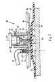
- a cutting machine according to the invention designated overall by 10, is represented only by a milling head 11 and the section of a - horizontal - machine table 12 arranged underneath it, which in turn is part of the machine frame 13, which is otherwise not shown on which the milling head can be moved back and forth in two mutually perpendicular coordinate directions, the longitudinal direction X direction, which is represented by arrow 14, and the perpendicular Y direction, which is represented by dashed arrow 16 is arranged.
- the cutting machine 10 is intended to be able to automatically cut 17 pieces with a predetermined contour from large-area, flexible material webs.
- the machine 10 is also intended to be capable of cutting plastic-coated textile webs that have a thickness of 1 mm to 3 mm.
- a finger milling cutter 18 is provided as the cutting tool, in which the course of its spiral-shaped cutting edges 19 is selected such that the material web 17 is raised when the milling cutter 18 rotates with the direction indicated by the arrow 21.
- the end mill 18 has the width of the kerf 22, which consists of the material web 17 ′′ determining diameter of 1 to about 3 mm and is designed as a double-edged or multi-edged milling cutter.
- the axial length over which the milling cutter 18 is provided with the spirally running milling or cutting edges 19 is approximately 12 to 15 mm. This part of the milling cutter 18 is referred to below as the "cutting section”.
- the end mill 18 is held in a conventional manner in a collet 23, which is rotatably mounted in the housing 24 of the milling head 11 about the vertical central axis 26, which also marks the longitudinal axis of the milling cutter 18, and can be driven by means of the drive motor 27, which is only indicated schematically.
- a basic tubular-tubular sleeve, generally designated 28, arranged on its underside by a base plate 29 is completed, which has a central bore 31 through which the free end portion of the end mill 18 emerges downwards, the free length l of the free measured between the free cutting edges 32 of the end mill 18 and the lower boundary surface 33 of the base plate 29 of the sleeve 28 End portion 18 'is slightly larger than the thickness d of the to be cut
- this free length l of the end mill 18 is 2 to 5 mm.
- the milling head 11 which in turn is supposed to be raised and lowered in the vertical direction represented by the arrow 34, is lowered so far that the free cutting edges 32 of the end mill 18 extend from the top 35 of the machine table 12 , on which the material web 17 rests over a large area, are arranged at a clear distance h which is a few millimeters, e.g. B. is between 2 and 5 mm.
- the circular edge 36 delimiting the central bore 31 of the base plate 29 against its lower boundary surface 33 is designed as a sharp-edged cutting edge, which is expediently hardened forms, on which fibers of a material web 17 formed as a textile material or milling chips of a material web 17 designed as a plastic film are cut off or sheared off.
- the diameter of the central bore 31 is selected only slightly larger than the effective diameter of the end mill 18.
- the bore diameter is only a few hundredths of a millimeter , e.g. B. 2 to 5/100 mm larger than the cutter diameter.
- the cutter 18 In order to be able to adjust the clear width of the ring or shear gap 37 remaining between the end mill 18 and the central "bore" 31, it may be expedient to give the cutter 18 a shape which tapers slightly towards its free end and the central bore 31 to give a complementary shape which widens correspondingly upwards, so that the width of this shear gap 37 can be adjusted by axially displacing the sleeve 28 relative to the milling cutter 18 or the housing 24.
- the “lifting” of the material web can take place at a suitable point of the machine 10, either at an edge section of the material web lying outside the machine table 12, or else it is e.g. B.
- a dashed groove 38 is provided, in the area of the cutter 18 or the milling head 11 can be lowered so far that the raw material web 17 is cut, after which the milling head - by lifting a few millimeters - in its the continuation of the cut 22 along the intended contour is brought to a suitable working height shown in FIG. 1.
- the thickness of the base plate 29 of the sleeve 28 corresponds in an expedient design 1/3 of the axial length of the cutting section of the end mill 18, on which this with the spiral cutting edges 19 is provided.
- the sleeve 28 is expediently set at a height on the housing 24 of the milling head 11, for. B. by tightening the locking screw 39 that the base plate 29 surrounds a central portion of the end mill 18, that is, whose spiral cutting edges 19 also extend into the area above the base plate 29, into which the milling cutter 18 rotates due to the rotation of the cutter 18. Chips or fiber particles are transported into it.
- the sleeve 28 is provided with large-area window recesses 41, which extend on both sides of the web 42 carrying the base plate 29 at its lower end over an at least 90 ° circumferential area of the sleeve 28.
- the milling chips or fibers can be blown out or extracted sufficiently freely.
- FIG. 2 to the details of which reference is now made, another embodiment of a cutting machine 10 according to the invention differs from that according to FIG. 1 only in that an overall lifting device designated 45 is provided, by means of which the for Cut processing provided - flexible - material web 17 in the area of the cutter 18 either temporarily, z. B. by performing the gate or can also be raised permanently if necessary, so that the milling cutter 18 or the milling head 11 can be held from the outset at the intended working height at which the clear distance h is present between the free cutting edges 32 of the milling cutter and the upper side 3 of the machine table 12 .
- an overall lifting device designated 45 is provided, by means of which the for Cut processing provided - flexible - material web 17 in the area of the cutter 18 either temporarily, z. B. by performing the gate or can also be raised permanently if necessary, so that the milling cutter 18 or the milling head 11 can be held from the outset at the intended working height at which the clear distance h is present between the free cutting edges 32 of the milling cutter and the upper
- a flat-plate-shaped hold-down ring 46 is attached to the sleeve 28, through the bottom opening 31 of which the end mill 18 passes, which typically has an outer diameter of 10-15 cm.
- This hold-down ring 46 has a flat, horizontally lower boundary surface 47 which connects centrally and smoothly to the lower, likewise flat boundary surface 33 of the base plate 29 of the sleeve 28.
- the outer edge 48 of the hold-down ring 46 is curved upwards with a smooth curvature, as can be seen in FIG. 2, in order to avoid damage to the material web 17, over which the hold-down ring 46 is guided together with the milling head 11.
- This hold-down ring 46 prevents wavy bulges or folds in the material web 17 in the region of the milling cutter.
- a connecting sleeve 49 is provided for a compressed air supply hose 51, the - vertical - compressed air passage channel of which connects to a nozzle opening 52 of the hold-down ring 46, through which the Compressed air supply hose 51 can supply pressurized compressed air to exit.
- the compressed air supply which had provided an "initial" lifting of the material web 17, can be switched off again. If this is not the case, this pneumatic lifting of the material web 17 can be maintained by continuing to supply compressed air via the hose 51 and the connecting nozzle 49 to the outlet nozzle 52.
- This lifting device 45 thus makes it possible to use a conventional milling machine, that is to say a milling machine that does not require any special design of the machine table 12, for the cutting processing of material webs 17 of the type mentioned.
- the material web 17 is here either as shown in the left part of FIG. 3 via an air-permeable material layer, for. B. a felt layer 54 over a large area, or, as shown in the right-hand part of FIG. 3, via flexible bristle bundles 56 arranged in a regular grid, as it were "punctually" and supported by this at a distance a from the top of a nozzle plate 57 keep, which has a regular distribution over its surface on its top opening suction nozzles 58, which are in communication with exhaust air channels 59, which in turn communicate with a suction nozzle 61 of the nozzle plate 57, which can be connected to the suction side of a suction fan (not shown). As shown, the nozzle plate 57 rests on the machine table 12 and, if necessary, can be fixed immovably thereon.
- the suction blower By means of the suction blower in the space between the material web 17 and the upper side of the nozzle plate 57, the negative pressure which can be generated, the material web 17 is pressed sufficiently firmly against its felt base, or held in contact with the bristle bundles 56, in order to carry out a cutting operation in the manner explained above Way to enable.
- a hold-down ring 46 can also be provided in combination with the milling head 11, as explained with reference to FIG. 2. It is also possible to hold the milling head 11 in contact with the base plate 29 of its sleeve 28 and, if appropriate, the hold-down ring 46 with the upper side of the material web 17 with a low pressing force, so that the material web in the area of the milling cutter 18 cannot move “upward”.
Landscapes
- Engineering & Computer Science (AREA)
- Textile Engineering (AREA)
- Mechanical Engineering (AREA)
- Treatment Of Fiber Materials (AREA)
Applications Claiming Priority (2)
| Application Number | Priority Date | Filing Date | Title |
|---|---|---|---|
| DE3818521 | 1988-05-31 | ||
| DE19883818521 DE3818521A1 (de) | 1988-05-31 | 1988-05-31 | Schneidmaschine fuer die herstellung von zuschnitten vorgegebener kontur aus einer grossflaechigen bahn eines flexiblen materials |
Publications (2)
| Publication Number | Publication Date |
|---|---|
| EP0345532A2 true EP0345532A2 (fr) | 1989-12-13 |
| EP0345532A3 EP0345532A3 (fr) | 1990-11-22 |
Family
ID=6355531
Family Applications (1)
| Application Number | Title | Priority Date | Filing Date |
|---|---|---|---|
| EP19890109338 Withdrawn EP0345532A3 (fr) | 1988-05-31 | 1989-05-24 | Machine de coupe pour l'usinage de pièces d'une certaine forme d'une bande large en matière flexible |
Country Status (2)
| Country | Link |
|---|---|
| EP (1) | EP0345532A3 (fr) |
| DE (1) | DE3818521A1 (fr) |
Cited By (3)
| Publication number | Priority date | Publication date | Assignee | Title |
|---|---|---|---|---|
| CN102145405A (zh) * | 2011-02-16 | 2011-08-10 | 南京航空航天大学 | 差动螺旋制孔装置及方法 |
| US20120006174A1 (en) * | 2010-07-12 | 2012-01-12 | Owens Corning Intellectual Capital, Llc | Rotary cutting apparatus and method |
| CN108687387A (zh) * | 2017-04-06 | 2018-10-23 | 东莞市恩慈自动化设备有限公司 | 全自动磨铁条机 |
Families Citing this family (1)
| Publication number | Priority date | Publication date | Assignee | Title |
|---|---|---|---|---|
| DE20203938U1 (de) | 2002-03-12 | 2002-06-06 | Wassmer Spezialmaschinen GmbH, 79423 Heitersheim | Bearbeitungsmaschine zum wenigstens teilweisen konturenabhängigen Ausschneiden oder Fräsen |
Family Cites Families (5)
| Publication number | Priority date | Publication date | Assignee | Title |
|---|---|---|---|---|
| US3535965A (en) * | 1968-05-06 | 1970-10-27 | Cincinnati Milling Machine Co | Hold down plate for use with material cutting machine |
| FR2031754A5 (fr) * | 1969-02-06 | 1970-11-20 | Cetih | |
| DE2046339A1 (de) * | 1970-09-19 | 1971-04-08 | Muto Industrial Co , Ltd ,Tokio | Automatische Schneidemaschine |
| DE2728794C2 (de) * | 1977-06-25 | 1984-03-29 | Aristo Graphic Systeme Gmbh & Co Kg, 2000 Hamburg | Fräskopf zum Ausschneiden von Schablonen aus Karton o.dgl. |
| US4515505A (en) * | 1982-10-28 | 1985-05-07 | International Business Machines Corporation | Pressure foot assembly for an end mill delete cutter |
-
1988
- 1988-05-31 DE DE19883818521 patent/DE3818521A1/de not_active Withdrawn
-
1989
- 1989-05-24 EP EP19890109338 patent/EP0345532A3/fr not_active Withdrawn
Cited By (5)
| Publication number | Priority date | Publication date | Assignee | Title |
|---|---|---|---|---|
| US20120006174A1 (en) * | 2010-07-12 | 2012-01-12 | Owens Corning Intellectual Capital, Llc | Rotary cutting apparatus and method |
| CN102145405A (zh) * | 2011-02-16 | 2011-08-10 | 南京航空航天大学 | 差动螺旋制孔装置及方法 |
| CN102145405B (zh) * | 2011-02-16 | 2012-11-21 | 南京航空航天大学 | 差动螺旋制孔装置及方法 |
| CN108687387A (zh) * | 2017-04-06 | 2018-10-23 | 东莞市恩慈自动化设备有限公司 | 全自动磨铁条机 |
| CN108687387B (zh) * | 2017-04-06 | 2019-07-16 | 东莞市恩慈自动化设备有限公司 | 全自动磨铁条机 |
Also Published As
| Publication number | Publication date |
|---|---|
| DE3818521A1 (de) | 1989-12-28 |
| EP0345532A3 (fr) | 1990-11-22 |
Similar Documents
| Publication | Publication Date | Title |
|---|---|---|
| DE2100605C3 (de) | Koordinatengesteuerte Vorrichtung zum Schneiden und Bohren von Flachmaterial, z.B. Gewebe | |
| DE4426717A1 (de) | Vorrichtung, insbesondere Oberfräse zur spanabhebenden Bearbeitung eines Werkstückes | |
| DE3616483C2 (fr) | ||
| DE3321954A1 (de) | Vorrichtung zum schneiden flaechigen materials | |
| EP0857817A2 (fr) | Appareil de nettoyage | |
| DE2911322C2 (de) | Maschine zum Entgraten und Säubern von flächigen Werkstücken | |
| DE2061703B2 (de) | Rollenschneidvorrichtung | |
| EP1122042A2 (fr) | Procédé et appareil pour fraiser une rainure dans un élément sous forme de plaque | |
| EP2616577B1 (fr) | Dispositif de coupe de fibre | |
| DE69102739T2 (de) | Holzbearbeitungsmaschine, wie z.B. Querschleifmaschine. | |
| CH407522A (de) | Vorrichtung zum Kantenbrechen, insbesondere von plattenförmigen Werkstücken aus Holz, Kunststoff o. dgl. | |
| DE2615365A1 (de) | Maschine fuer die beseitigung von staub von blattmaterial | |
| DE2746086B2 (de) | Vorrichtung zum Zuschneiden von Stofflagenpaketen o.dgl | |
| DE3103958C2 (de) | Vorrichtung zum Abspalten eines Materialstreifens von einer bewegten Materialbahn | |
| DE3818521A1 (de) | Schneidmaschine fuer die herstellung von zuschnitten vorgegebener kontur aus einer grossflaechigen bahn eines flexiblen materials | |
| EP1405944A2 (fr) | Procédé pour découper des pièces d'une bande de matière textile pour la fabrication d'ouvrages composites de résines et fibres | |
| DE2807954B2 (de) | Vorrichtung zum Herstellen eines gewölbten Segels | |
| EP0527485A1 (fr) | Machine à déchiqueter | |
| DE3814228A1 (de) | Fraesmaschine | |
| DE102004020256A1 (de) | Schneidmesser für Rotationsschneidanlagen | |
| EP0221374B1 (fr) | Installation de tonte d'une bande en déplacement | |
| DE4013050C2 (fr) | ||
| CH593378A5 (en) | Trimming machine for flat materials, esp. carpet patterns - is easily adjusted, trims and cleans off pile fragments | |
| DE4115555C2 (de) | Vorrichtung zum Scheren von Textilwarenbahnen | |
| EP0035657B1 (fr) | Tondeuse à gazou à fil de coupe tournant |
Legal Events
| Date | Code | Title | Description |
|---|---|---|---|
| PUAI | Public reference made under article 153(3) epc to a published international application that has entered the european phase |
Free format text: ORIGINAL CODE: 0009012 |
|
| AK | Designated contracting states |
Kind code of ref document: A2 Designated state(s): AT BE CH DE ES FR GB GR IT LI LU NL SE |
|
| RBV | Designated contracting states (corrected) |
Designated state(s): AT CH DE FR GB IT LI |
|
| PUAL | Search report despatched |
Free format text: ORIGINAL CODE: 0009013 |
|
| AK | Designated contracting states |
Kind code of ref document: A3 Designated state(s): AT BE CH DE ES FR GB GR IT LI LU NL SE |
|
| 16A | New documents despatched to applicant after publication of the search report | ||
| STAA | Information on the status of an ep patent application or granted ep patent |
Free format text: STATUS: THE APPLICATION IS DEEMED TO BE WITHDRAWN |
|
| 18D | Application deemed to be withdrawn |
Effective date: 19910523 |