EP0345536A2 - Guide linéaire - Google Patents
Guide linéaire Download PDFInfo
- Publication number
- EP0345536A2 EP0345536A2 EP89109359A EP89109359A EP0345536A2 EP 0345536 A2 EP0345536 A2 EP 0345536A2 EP 89109359 A EP89109359 A EP 89109359A EP 89109359 A EP89109359 A EP 89109359A EP 0345536 A2 EP0345536 A2 EP 0345536A2
- Authority
- EP
- European Patent Office
- Prior art keywords
- guide
- shaft
- carriage
- linear
- guide shaft
- Prior art date
- Legal status (The legal status is an assumption and is not a legal conclusion. Google has not performed a legal analysis and makes no representation as to the accuracy of the status listed.)
- Granted
Links
- 230000002093 peripheral effect Effects 0.000 claims 1
- 230000004907 flux Effects 0.000 description 4
- 238000010276 construction Methods 0.000 description 2
- 238000006073 displacement reaction Methods 0.000 description 2
- 238000009434 installation Methods 0.000 description 2
- 238000005553 drilling Methods 0.000 description 1
- 238000005516 engineering process Methods 0.000 description 1
- 230000006698 induction Effects 0.000 description 1
- 230000001939 inductive effect Effects 0.000 description 1
- 238000011089 mechanical engineering Methods 0.000 description 1
- 239000007787 solid Substances 0.000 description 1
- 230000007704 transition Effects 0.000 description 1
Images


Classifications
-
- F—MECHANICAL ENGINEERING; LIGHTING; HEATING; WEAPONS; BLASTING
- F16—ENGINEERING ELEMENTS AND UNITS; GENERAL MEASURES FOR PRODUCING AND MAINTAINING EFFECTIVE FUNCTIONING OF MACHINES OR INSTALLATIONS; THERMAL INSULATION IN GENERAL
- F16H—GEARING
- F16H19/00—Gearings comprising essentially only toothed gears or friction members and not capable of conveying indefinitely-continuing rotary motion
- F16H19/02—Gearings comprising essentially only toothed gears or friction members and not capable of conveying indefinitely-continuing rotary motion for interconverting rotary or oscillating motion and reciprocating motion
- F16H19/04—Gearings comprising essentially only toothed gears or friction members and not capable of conveying indefinitely-continuing rotary motion for interconverting rotary or oscillating motion and reciprocating motion comprising a rack
-
- B—PERFORMING OPERATIONS; TRANSPORTING
- B23—MACHINE TOOLS; METAL-WORKING NOT OTHERWISE PROVIDED FOR
- B23Q—DETAILS, COMPONENTS, OR ACCESSORIES FOR MACHINE TOOLS, e.g. ARRANGEMENTS FOR COPYING OR CONTROLLING; MACHINE TOOLS IN GENERAL CHARACTERISED BY THE CONSTRUCTION OF PARTICULAR DETAILS OR COMPONENTS; COMBINATIONS OR ASSOCIATIONS OF METAL-WORKING MACHINES, NOT DIRECTED TO A PARTICULAR RESULT
- B23Q1/00—Members which are comprised in the general build-up of a form of machine, particularly relatively large fixed members
- B23Q1/25—Movable or adjustable work or tool supports
- B23Q1/44—Movable or adjustable work or tool supports using particular mechanisms
- B23Q1/56—Movable or adjustable work or tool supports using particular mechanisms with sliding pairs only, the sliding pairs being the first two elements of the mechanism
- B23Q1/58—Movable or adjustable work or tool supports using particular mechanisms with sliding pairs only, the sliding pairs being the first two elements of the mechanism a single sliding pair
-
- B—PERFORMING OPERATIONS; TRANSPORTING
- B23—MACHINE TOOLS; METAL-WORKING NOT OTHERWISE PROVIDED FOR
- B23Q—DETAILS, COMPONENTS, OR ACCESSORIES FOR MACHINE TOOLS, e.g. ARRANGEMENTS FOR COPYING OR CONTROLLING; MACHINE TOOLS IN GENERAL CHARACTERISED BY THE CONSTRUCTION OF PARTICULAR DETAILS OR COMPONENTS; COMBINATIONS OR ASSOCIATIONS OF METAL-WORKING MACHINES, NOT DIRECTED TO A PARTICULAR RESULT
- B23Q37/00—Metal-working machines, or constructional combinations thereof, built-up from units designed so that at least some of the units can form parts of different machines or combinations; Units therefor in so far as the feature of interchangeability is important
-
- F—MECHANICAL ENGINEERING; LIGHTING; HEATING; WEAPONS; BLASTING
- F16—ENGINEERING ELEMENTS AND UNITS; GENERAL MEASURES FOR PRODUCING AND MAINTAINING EFFECTIVE FUNCTIONING OF MACHINES OR INSTALLATIONS; THERMAL INSULATION IN GENERAL
- F16C—SHAFTS; FLEXIBLE SHAFTS; ELEMENTS OR CRANKSHAFT MECHANISMS; ROTARY BODIES OTHER THAN GEARING ELEMENTS; BEARINGS
- F16C29/00—Bearings for parts moving only linearly
-
- F—MECHANICAL ENGINEERING; LIGHTING; HEATING; WEAPONS; BLASTING
- F16—ENGINEERING ELEMENTS AND UNITS; GENERAL MEASURES FOR PRODUCING AND MAINTAINING EFFECTIVE FUNCTIONING OF MACHINES OR INSTALLATIONS; THERMAL INSULATION IN GENERAL
- F16C—SHAFTS; FLEXIBLE SHAFTS; ELEMENTS OR CRANKSHAFT MECHANISMS; ROTARY BODIES OTHER THAN GEARING ELEMENTS; BEARINGS
- F16C2322/00—Apparatus used in shaping articles
- F16C2322/39—General buildup of machine tools, e.g. spindles, slides, actuators
Definitions
- the invention relates to a linear guide with at least one guide shaft mounted in bearing blocks, on which a guide carriage is arranged, the guide shaft and the guide carriage being displaceable relative to one another and the guide carriage being provided with drive members for generating a relative movement between the guide shaft and the guide carriage.
- Linear guides are used to perform linear movements in many areas, such as in mechanical engineering, handling technology, fixture construction and precision engineering.
- Linear guides can be used as building blocks for Grippers, robots, sliding tables, holders, measuring tools and the like can be used.
- the core of the linear guide is formed by one or two guide shafts, on which or on which a guide slide is arranged, which is displaceable along the shaft or shafts. In reverse, however, the guide carriage can also remain stationary and the one or the two shafts are displaced.
- So-called ball bushings or linear ball bearings with a plurality of ball revolutions are generally arranged in the guide carriage for low-friction displacement and a high load capacity.
- the relative movement between the guide shaft and the guide slide arranged thereon can be achieved in various ways.
- Ball screws are known for this purpose, a spindle running parallel to the guide shaft and a spindle nut being arranged in the guide carriage. If the spindle is driven, the guide carriage moves accordingly.
- the present invention is therefore based on the object of providing a linear guide of the type mentioned at the outset, which can be used universally in a small size and, if necessary, a high load, is particularly versatile and can be combined with different sizes to form a modular system.
- this object is achieved in that the guide shaft is provided over a partial circumferential region with a toothing which cooperates with a pinion mounted in the guide carriage, the guide carriage being at least partially provided with standard dimensions and standard connecting parts in such a way that several guide carriages and guide shafts cooperating with them are connectable and combinable according to the modular principle.
- the hardened guide shaft or, in the case of a double linear guide, the two hardened guide shafts are provided with a hardened toothing and in this way form both the guide and an element of the drive. In this way, a very compact size is achieved. This means that additional complex mechanical drive elements can be omitted.
- the space between two parallel guide shafts remains free as a work area for the vertical Z axis.
- linear guides can be connected to form a unit in any way. In this way, linear movements can take place in several axial directions, which is particularly advantageous for robot work.
- the linear guide according to the invention is also significantly lighter in weight and, furthermore, its design provides a large area of application.
- a very significant advantage over known linear guides is that practically unlimited guide lengths are possible. If necessary, it is only necessary according to Füh Arrange waves approximately one behind the other, it is only necessary to ensure that the teeth in the transition area are adapted to each other.
- the guide shaft can be installed in any way in the linear guide so that the toothing incorporated therein e.g. is in the lower or upper area of the guide shaft or on one side. Both straight and helical teeth can be provided as teeth.
- an arrangement of the toothing on one side or in the upper area gives the possibility of supporting the guide shaft on the underside in a support bearing or a support rail, which provides a high load capacity and large feed forces are possible.
- the guide shaft with its toothing which forms the core of the present invention, will generally be inductively hardened.
- the toothing will be introduced into the unhardened guide shaft, after which the inductive hardening is carried out with a round inductor.
- the magnetic flux during induction hardening and thus the temperature of the teeth to be hardened are advantageously used Control the guide shaft so that the magnetic flux is lower in the area of the teeth than in the rest of the area. This can be done, for example, by the fact that the magnetic flux in the non-toothed region of the guide shaft is higher due to laminated cores distributed over the circumference of the round inductor, which result in an increase in magnetic flux. In this case, it is only necessary to push the guide shaft to be hardened through the round inductor without twisting.
- the toothing extends over approximately one fifth of the circumferential area of the guide shaft.
- the toothing can only extend between two linear ball bearings.
- four linear ball bearings, which are regularly distributed over the circumference, are provided in a ball bushing, so that the toothing is of sufficient width.
- the drive shaft on which the pinion is arranged is designed as a through shaft and connected directly or indirectly to a second drive shaft is on which a second pinion works together with the teeth of the second guide shaft.
- the drive shaft can also be made so long that both pinions are arranged on it.
- a further guide carriage is arranged on the guide carriage so that the longitudinal axis of the second guide shaft cooperating therewith is perpendicular to the longitudinal axis of the first guide shaft, a linear guide is created with movements in two axial directions possible are.
- a movement in all three axial directions results if a further development provides that a third guide carriage is provided which cooperates with a third guide shaft, the longitudinal axis of which is perpendicular to the longitudinal axis of the second guide shaft and perpendicular to the longitudinal axis of the first guide shaft.
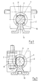
- the line guides according to the invention according to FIGS. 1 to 3 are basically of the same structure. The main difference lies only in the installation of a guide shaft 1.
- a guide shaft 1 is surrounded in a known manner by a guide slide 2 which is provided with a ball bushing 3 which has four linear revolutions 4 arranged regularly distributed over the circumference in order to enable a relative movement between the guide shaft 1 and the guide slide 2.
- the guide shaft 1 can as Solid shaft or of course also be designed as a hollow shaft.
- the guide shaft 1 is provided on the underside with a cross toothing 5.
- the transverse toothing 5 works together with a pinion 6 which is fastened on a drive shaft 7.
- the drive shaft 7 is supported in the guide carriage 2 via ball bearings 8 and 9.
- the drive shaft 7 is connected to a drive motor 10 (see FIGS. 4 to 6) which is flanged to the corresponding side of the guide carriage 2.
- the drive shaft 7 shown in FIG. 1 is designed as a through shaft, with which a drive connection to a second guide carriage or a second drive shaft, which is connected to the first guide carriage 2 and thus to a drive connection and together with a drive link, may be created second guide shaft forms a double linear guide.
- the guide shaft provided with the toothing 5 also suitable for use in a linear guide according to DE-OS 34 28 680.
- the drive shaft 7 can of course also end inside the guide carriage 2 if only a simple linear guide is provided or if no drive is provided for a double linear guide for the second guide carriage or if the guide carriage 2 also comprises the second guide shaft as a common guide carriage .
- FIG. 2 shows another embodiment of the installation of the guide shaft 1 in a linear guide.
- the transverse toothing 5 is located on the top side, which means that when using a ball bushing 3 with a correspondingly large slot 12 on the underside, it is possible to support the guide shaft 1 on a mounting rail 11 and to connect it to it, which is e.g. can be done via screws.
- the transverse toothing 5 of the guide shaft 1 is arranged on one side, as shown in FIG. 3, it is also possible to completely support the guide shaft 1 on the underside on the mounting rail 11, with which high forces can be transmitted.
- the drive motor 10 on the top of the guide carriage 2 flanges.
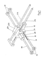
- FIGS. 4 to 6 Possible types of linear guide systems are shown in FIGS. 4 to 6, for example.
- FIG. 4 shows two double linear guides connected to one another, wherein movement possibilities are possible in two mutually perpendicular axial directions.
- a first double linear guide wherein a guide shaft 1A is provided with transverse teeth 5 on the upper side, while the second guide shaft 1B is this linear guide without drive, is connected to a second linear guide which has two guide shafts 21A and 21B.
- the second linear guide too, only one guide shaft, namely the guide shaft 21A, is provided with transverse teeth and thus with a drive.
- the drive takes place in accordance with the configurations shown in FIGS. 1 to 3, each with a drive motor 10 and an associated pinion in the interior of the guide carriage 2A or 22A.
- the guide carriage 2B of the first linear guide is over the two guide carriages 22A and 22B attached to the top of the guide carriages 2A and 2B in fixed connection with the driven guide carriage 2A.
- the guide carriages 2A, 2B, 22A and 22B have the same external dimensions and also have correspondingly standardized connecting parts, such as Standard holes on which screw connections can be made.
- the linear guide system according to FIG. 4 is supported in shaft bearings 13.
- the guide carriage 32 which is designed as a double guide carriage for a double linear guide, is expediently so wide in its width that the guide carriages 2A, 2B or 22A and 22B can be arranged on it in three positions, in each case on the outside or in the center, for which purpose corresponding drilling patterns are used .
- the length and width of the guide carriage 32 coincide with the length of the guide carriages 2A, 2B or 22A, 22B, which means that their attachment can also be rotated by 90 degrees.
- the linear guide system according to FIG. 5 is supported in two storage racks 24 via bearing blocks 25.
- the two guide shafts 1A and 1B of the first linear guide are mounted, in which case the guide shaft 1B is provided with transverse toothing which, according to the exemplary embodiment according to FIG. 3, lies on the rear side, with the drive motor 10 accordingly on the Top is flanged.
- a transverse displacement is possible with the first linear guide.
- the second guide carriage 42 flanged to the first guide carriage 32, a second possibility of movement in the vertical direction is made possible by the second linear guide via the guide shaft 41, which is secured against rotation if necessary, and its toothing 5.
- a robot arm 26 can be arranged on the underside, which can carry out movements in two axial directions in this way.
- a linear guide system is shown in FIG. 6, by means of which movements in all three axial directions are possible.
- the basis is a first linear guide with two guide shafts 1A and 1B and guide carriages 2A and 2B, the guide shaft 1A is provided on the upper side with the transverse toothing 5.
- the guide shaft 1A like the guide shaft 1B of conventional design, can be completely supported and fastened on its underside on a mounting rail 11 (corresponding to FIG. 2).
- the two support rails 11 are fastened to a support frame 27.
- the drive motor 10 is provided with a reduction gear 28 for displacing the guide carriage 2A along the guide shaft 1A, by means of which it is flanged to the guide carriage 2A.
- the guide carriage 2B is thus also displaced via the connection through the second linear guide, which is arranged above the first linear guide.
- a third guide carriage 32A which is flanged onto the two guide carriages 22A and 22B on the upper side in such a way that the two guide carriages 22A and 22B are connected to one another and thus form a unit, together with two vertical guide shafts 31A and 31B provide a possibility of vertical movement direction given.
- the guide shaft 31A is in turn provided with a toothing (on the rear side and therefore not shown), whereby there is a drive connection via the drive motor 10 and a reduction gear 28 which is flanged to one side of the guide carriage 32A.
- a link chain 33 is used to supply the drive power for driving the drive motors 10, which are designed in a simple manner as electric motors, so that the energy is supplied via electrical cables.
Landscapes
- Engineering & Computer Science (AREA)
- General Engineering & Computer Science (AREA)
- Mechanical Engineering (AREA)
- Transmission Devices (AREA)
Applications Claiming Priority (2)
| Application Number | Priority Date | Filing Date | Title |
|---|---|---|---|
| DE3819278 | 1988-06-07 | ||
| DE3819278A DE3819278A1 (de) | 1988-06-07 | 1988-06-07 | Linearfuehrung |
Publications (3)
| Publication Number | Publication Date |
|---|---|
| EP0345536A2 true EP0345536A2 (fr) | 1989-12-13 |
| EP0345536A3 EP0345536A3 (en) | 1990-10-31 |
| EP0345536B1 EP0345536B1 (fr) | 1994-04-27 |
Family
ID=6355995
Family Applications (1)
| Application Number | Title | Priority Date | Filing Date |
|---|---|---|---|
| EP89109359A Expired - Lifetime EP0345536B1 (fr) | 1988-06-07 | 1989-05-24 | Guide linéaire |
Country Status (2)
| Country | Link |
|---|---|
| EP (1) | EP0345536B1 (fr) |
| DE (2) | DE3819278A1 (fr) |
Cited By (6)
| Publication number | Priority date | Publication date | Assignee | Title |
|---|---|---|---|---|
| EP0534875A1 (fr) * | 1991-09-27 | 1993-03-31 | Kinetic Technologies (S.A.) | Module de guidage pour effectuer une translation linéaire |
| EP0576378A1 (fr) * | 1992-06-25 | 1993-12-29 | Kinetic Technologies (S.A.) | Module linéaire de guidage pour la translation et la manutention de toutes pièces et accessoires |
| EP0585563A1 (fr) * | 1992-09-04 | 1994-03-09 | Lean-Technik R. Janzen | Dispositif pour la génération d'un mouvement synchrone de translation/rotation |
| DE10312008A1 (de) * | 2003-03-19 | 2004-09-30 | Ina-Schaeffler Kg | Linearantriebseinheit |
| CN101285502B (zh) * | 2007-01-15 | 2011-08-10 | 费斯托股份有限两合公司 | 线性驱动器 |
| US20210001479A1 (en) * | 2018-03-15 | 2021-01-07 | Igus Gmbh | Arm joint for a manipulator and manipulator |
Families Citing this family (6)
| Publication number | Priority date | Publication date | Assignee | Title |
|---|---|---|---|---|
| JP2567928Y2 (ja) * | 1992-08-11 | 1998-04-08 | 日本精工株式会社 | ラック一体型リニアガイド装置 |
| US5546826A (en) * | 1994-01-13 | 1996-08-20 | Yanagisawa; Ken | Drive system |
| DE102006035181A1 (de) * | 2006-07-29 | 2008-01-31 | Schaeffler Kg | Linearbewegungsführung für einen linear verfahrbaren Schlitten |
| EP2008764B1 (fr) | 2007-06-29 | 2009-09-23 | WAFIOS Aktiengesellschaft | Guidage linéaire |
| DE102013210835A1 (de) * | 2013-06-11 | 2014-12-11 | Thyssenkrupp System Engineering Gmbh | Falzvorrichtung und Verfahren zum Falzen eines Werkstücks |
| JP7298346B2 (ja) * | 2019-07-03 | 2023-06-27 | 株式会社アイシン | 支持装置 |
Family Cites Families (4)
| Publication number | Priority date | Publication date | Assignee | Title |
|---|---|---|---|---|
| US2945366A (en) * | 1958-10-06 | 1960-07-19 | Beaver Prec Products Inc | Ball spline assembly |
| FR2387733A1 (fr) * | 1977-04-20 | 1978-11-17 | Micro Controle | Dispositif pour la commande de deplacement d'appareils |
| GB2136529B (en) * | 1983-03-11 | 1986-04-09 | Cam Systems Limited | Linear actuator |
| GB2142410A (en) * | 1983-07-01 | 1985-01-16 | Ciniglio A J | Improvements in or relating to linear actuators |
-
1988
- 1988-06-07 DE DE3819278A patent/DE3819278A1/de not_active Withdrawn
-
1989
- 1989-05-24 DE DE58907548T patent/DE58907548D1/de not_active Expired - Fee Related
- 1989-05-24 EP EP89109359A patent/EP0345536B1/fr not_active Expired - Lifetime
Cited By (8)
| Publication number | Priority date | Publication date | Assignee | Title |
|---|---|---|---|---|
| EP0534875A1 (fr) * | 1991-09-27 | 1993-03-31 | Kinetic Technologies (S.A.) | Module de guidage pour effectuer une translation linéaire |
| FR2681805A1 (fr) * | 1991-09-27 | 1993-04-02 | Coron Jean Paul | Module lineaire de guidage pour la translation et la manutention de toutes pieces et accessoires. |
| EP0576378A1 (fr) * | 1992-06-25 | 1993-12-29 | Kinetic Technologies (S.A.) | Module linéaire de guidage pour la translation et la manutention de toutes pièces et accessoires |
| EP0585563A1 (fr) * | 1992-09-04 | 1994-03-09 | Lean-Technik R. Janzen | Dispositif pour la génération d'un mouvement synchrone de translation/rotation |
| DE10312008A1 (de) * | 2003-03-19 | 2004-09-30 | Ina-Schaeffler Kg | Linearantriebseinheit |
| CN101285502B (zh) * | 2007-01-15 | 2011-08-10 | 费斯托股份有限两合公司 | 线性驱动器 |
| US20210001479A1 (en) * | 2018-03-15 | 2021-01-07 | Igus Gmbh | Arm joint for a manipulator and manipulator |
| US11865712B2 (en) * | 2018-03-15 | 2024-01-09 | Igus Gmbh | Arm joint for a manipulator and manipulator |
Also Published As
| Publication number | Publication date |
|---|---|
| EP0345536A3 (en) | 1990-10-31 |
| EP0345536B1 (fr) | 1994-04-27 |
| DE58907548D1 (de) | 1994-06-01 |
| DE3819278A1 (de) | 1989-12-14 |
Similar Documents
| Publication | Publication Date | Title |
|---|---|---|
| DE4224032C2 (de) | Antriebssystem | |
| EP0345536B1 (fr) | Guide linéaire | |
| EP0218878B1 (fr) | Robot industriel du type à pont roulant | |
| EP0207215A1 (fr) | Glissière | |
| EP1642673B1 (fr) | Machine outil | |
| WO2020160936A1 (fr) | Ensemble de transfert pour un système d'ascenseur | |
| DE7710097U1 (de) | Seitenwand eines tragwagens | |
| DE2550831C2 (de) | Antriebskupplung | |
| EP0193749A1 (fr) | Unité mécanique de commande linéaire | |
| DE102013226826A1 (de) | Linearmotoranordnung und Werkzeugmaschine mit einer Linearmotoranordnung | |
| DE102009005785A1 (de) | Spindelantrieb | |
| EP0585563B1 (fr) | Dispositif pour la génération d'un mouvement synchrone de translation/rotation | |
| WO2005123339A2 (fr) | Meuleuse configuree sous la forme d'une meuleuse cylindrique/non cylindrique universelle | |
| DE19920672B4 (de) | Lineare Stellvorrichtung | |
| EP1108906A1 (fr) | Dispositif de guide lineaire | |
| DE3136552A1 (de) | Linearantrieb fuer einen schlitten | |
| DE19614513B4 (de) | Linearwälzlager mit einer U-förmigen Führungsschiene | |
| DE8912348U1 (de) | Schrittantriebsvorrichtung | |
| EP0345535B1 (fr) | Procédé de fabrication d'une tige de guidage trempée pour un guide linéaire | |
| DE29808916U1 (de) | Trennwandelement mit eigener Antriebseinrichtung | |
| DE4442470C2 (de) | Plotter bzw. Bearbeitungsplotter | |
| EP0105246A1 (fr) | Dispositif d'entraînement et de guidage avec un vérin et un élément de transmission | |
| DE8430296U1 (de) | Kupplungseinrichtung zur Verbindung zweier auf einem gemeinsamen Bett gelagerter Werkzeugmaschinentische | |
| DE102018205781A1 (de) | Antriebseinrichtung | |
| DE69620594T2 (de) | Elektrisches Stellglied |
Legal Events
| Date | Code | Title | Description |
|---|---|---|---|
| PUAI | Public reference made under article 153(3) epc to a published international application that has entered the european phase |
Free format text: ORIGINAL CODE: 0009012 |
|
| AK | Designated contracting states |
Kind code of ref document: A2 Designated state(s): DE ES FR GB IT NL SE |
|
| PUAL | Search report despatched |
Free format text: ORIGINAL CODE: 0009013 |
|
| AK | Designated contracting states |
Kind code of ref document: A3 Designated state(s): DE ES FR GB IT NL SE |
|
| 17P | Request for examination filed |
Effective date: 19901217 |
|
| 17Q | First examination report despatched |
Effective date: 19920121 |
|
| GRAA | (expected) grant |
Free format text: ORIGINAL CODE: 0009210 |
|
| AK | Designated contracting states |
Kind code of ref document: B1 Designated state(s): DE ES FR GB IT NL SE |
|
| PG25 | Lapsed in a contracting state [announced via postgrant information from national office to epo] |
Ref country code: ES Free format text: LAPSE BECAUSE OF NON-PAYMENT OF DUE FEES Effective date: 19940525 |
|
| REF | Corresponds to: |
Ref document number: 58907548 Country of ref document: DE Date of ref document: 19940601 |
|
| GBT | Gb: translation of ep patent filed (gb section 77(6)(a)/1977) |
Effective date: 19940506 |
|
| ET | Fr: translation filed | ||
| ITF | It: translation for a ep patent filed | ||
| EAL | Se: european patent in force in sweden |
Ref document number: 89109359.3 |
|
| PLBE | No opposition filed within time limit |
Free format text: ORIGINAL CODE: 0009261 |
|
| STAA | Information on the status of an ep patent application or granted ep patent |
Free format text: STATUS: NO OPPOSITION FILED WITHIN TIME LIMIT |
|
| 26N | No opposition filed | ||
| REG | Reference to a national code |
Ref country code: GB Ref legal event code: 732E |
|
| REG | Reference to a national code |
Ref country code: FR Ref legal event code: TP |
|
| PGFP | Annual fee paid to national office [announced via postgrant information from national office to epo] |
Ref country code: GB Payment date: 20000509 Year of fee payment: 12 |
|
| PGFP | Annual fee paid to national office [announced via postgrant information from national office to epo] |
Ref country code: SE Payment date: 20000516 Year of fee payment: 12 |
|
| PGFP | Annual fee paid to national office [announced via postgrant information from national office to epo] |
Ref country code: NL Payment date: 20000524 Year of fee payment: 12 Ref country code: FR Payment date: 20000524 Year of fee payment: 12 |
|
| PGFP | Annual fee paid to national office [announced via postgrant information from national office to epo] |
Ref country code: DE Payment date: 20000527 Year of fee payment: 12 |
|
| PG25 | Lapsed in a contracting state [announced via postgrant information from national office to epo] |
Ref country code: GB Free format text: LAPSE BECAUSE OF NON-PAYMENT OF DUE FEES Effective date: 20010524 |
|
| PG25 | Lapsed in a contracting state [announced via postgrant information from national office to epo] |
Ref country code: SE Free format text: LAPSE BECAUSE OF NON-PAYMENT OF DUE FEES Effective date: 20010525 |
|
| PG25 | Lapsed in a contracting state [announced via postgrant information from national office to epo] |
Ref country code: NL Free format text: LAPSE BECAUSE OF NON-PAYMENT OF DUE FEES Effective date: 20011201 |
|
| GBPC | Gb: european patent ceased through non-payment of renewal fee |
Effective date: 20010524 |
|
| PG25 | Lapsed in a contracting state [announced via postgrant information from national office to epo] |
Ref country code: FR Free format text: LAPSE BECAUSE OF NON-PAYMENT OF DUE FEES Effective date: 20020131 |
|
| NLV4 | Nl: lapsed or anulled due to non-payment of the annual fee |
Effective date: 20011201 |
|
| PG25 | Lapsed in a contracting state [announced via postgrant information from national office to epo] |
Ref country code: DE Free format text: LAPSE BECAUSE OF NON-PAYMENT OF DUE FEES Effective date: 20020301 |
|
| REG | Reference to a national code |
Ref country code: ES Ref legal event code: FD2A Effective date: 19950610 |
|
| PG25 | Lapsed in a contracting state [announced via postgrant information from national office to epo] |
Ref country code: IT Free format text: LAPSE BECAUSE OF NON-PAYMENT OF DUE FEES;WARNING: LAPSES OF ITALIAN PATENTS WITH EFFECTIVE DATE BEFORE 2007 MAY HAVE OCCURRED AT ANY TIME BEFORE 2007. THE CORRECT EFFECTIVE DATE MAY BE DIFFERENT FROM THE ONE RECORDED. Effective date: 20050524 |