EP0345545A2 - Suppression de bruit d'écoulement pour des vannes électroniques - Google Patents
Suppression de bruit d'écoulement pour des vannes électroniques Download PDFInfo
- Publication number
- EP0345545A2 EP0345545A2 EP89109384A EP89109384A EP0345545A2 EP 0345545 A2 EP0345545 A2 EP 0345545A2 EP 89109384 A EP89109384 A EP 89109384A EP 89109384 A EP89109384 A EP 89109384A EP 0345545 A2 EP0345545 A2 EP 0345545A2
- Authority
- EP
- European Patent Office
- Prior art keywords
- compressor
- valve
- pulsing
- frequency
- expansion valve
- Prior art date
- Legal status (The legal status is an assumption and is not a legal conclusion. Google has not performed a legal analysis and makes no representation as to the accuracy of the status listed.)
- Withdrawn
Links
- 238000000034 method Methods 0.000 claims abstract description 20
- 238000005057 refrigeration Methods 0.000 claims abstract description 10
- 239000003507 refrigerant Substances 0.000 claims description 30
- 238000005086 pumping Methods 0.000 claims 3
- 238000001816 cooling Methods 0.000 claims 2
- 230000003247 decreasing effect Effects 0.000 claims 1
- 230000000737 periodic effect Effects 0.000 claims 1
- 238000004378 air conditioning Methods 0.000 abstract description 9
- 239000007788 liquid Substances 0.000 description 7
- 239000000463 material Substances 0.000 description 2
- 238000007630 basic procedure Methods 0.000 description 1
- 230000008030 elimination Effects 0.000 description 1
- 238000003379 elimination reaction Methods 0.000 description 1
- 239000000446 fuel Substances 0.000 description 1
- 230000004048 modification Effects 0.000 description 1
- 238000012986 modification Methods 0.000 description 1
Images


Classifications
-
- F—MECHANICAL ENGINEERING; LIGHTING; HEATING; WEAPONS; BLASTING
- F16—ENGINEERING ELEMENTS AND UNITS; GENERAL MEASURES FOR PRODUCING AND MAINTAINING EFFECTIVE FUNCTIONING OF MACHINES OR INSTALLATIONS; THERMAL INSULATION IN GENERAL
- F16L—PIPES; JOINTS OR FITTINGS FOR PIPES; SUPPORTS FOR PIPES, CABLES OR PROTECTIVE TUBING; MEANS FOR THERMAL INSULATION IN GENERAL
- F16L55/00—Devices or appurtenances for use in, or in connection with, pipes or pipe systems
- F16L55/02—Energy absorbers; Noise absorbers
- F16L55/033—Noise absorbers
- F16L55/0333—Noise absorbers by means of an active system
-
- F—MECHANICAL ENGINEERING; LIGHTING; HEATING; WEAPONS; BLASTING
- F25—REFRIGERATION OR COOLING; COMBINED HEATING AND REFRIGERATION SYSTEMS; HEAT PUMP SYSTEMS; MANUFACTURE OR STORAGE OF ICE; LIQUEFACTION SOLIDIFICATION OF GASES
- F25B—REFRIGERATION MACHINES, PLANTS OR SYSTEMS; COMBINED HEATING AND REFRIGERATION SYSTEMS; HEAT PUMP SYSTEMS
- F25B41/00—Fluid-circulation arrangements
- F25B41/30—Expansion means; Dispositions thereof
- F25B41/31—Expansion valves
- F25B41/34—Expansion valves with the valve member being actuated by electric means, e.g. by piezoelectric actuators
- F25B41/345—Expansion valves with the valve member being actuated by electric means, e.g. by piezoelectric actuators by solenoids
- F25B41/347—Expansion valves with the valve member being actuated by electric means, e.g. by piezoelectric actuators by solenoids with the valve member being opened and closed cyclically, e.g. with pulse width modulation
-
- Y—GENERAL TAGGING OF NEW TECHNOLOGICAL DEVELOPMENTS; GENERAL TAGGING OF CROSS-SECTIONAL TECHNOLOGIES SPANNING OVER SEVERAL SECTIONS OF THE IPC; TECHNICAL SUBJECTS COVERED BY FORMER USPC CROSS-REFERENCE ART COLLECTIONS [XRACs] AND DIGESTS
- Y02—TECHNOLOGIES OR APPLICATIONS FOR MITIGATION OR ADAPTATION AGAINST CLIMATE CHANGE
- Y02B—CLIMATE CHANGE MITIGATION TECHNOLOGIES RELATED TO BUILDINGS, e.g. HOUSING, HOUSE APPLIANCES OR RELATED END-USER APPLICATIONS
- Y02B30/00—Energy efficient heating, ventilation or air conditioning [HVAC]
- Y02B30/70—Efficient control or regulation technologies, e.g. for control of refrigerant flow, motor or heating
Definitions
- the present invention relates to expansion valves for controlling flow of refrigerant between the exothermic heat exchanger or condenser and the endothermic heat exchanger or evaporator in a refrigeration or air conditioning system.
- Valves of this type are employed for creating a sufficient pressure drop and expansion of the refrigerant prior to entry into the evaporator.
- Refrigeration systems of this type typically consist of a compressor to compress the refrigerant vapors, a condenser to condense compressed refrigerant vapors to liquid, an expansion valve, and an evaporator in which low pressure refrigerant liquid is vaporized, in connection with which the medium surrounding the evaporator coils is cooled.
- Electrically-actuated expansion valves typically operate by pulsing refrigerant material through the valve at a pulse rate controlled by the frequency with which a certain member of the valve oscillates back and forth.
- One problem common to electrically-actuated refrigerant expansion valves is the creation of excessive noise at the expansion valve for a short period of time after the compressor is energized. This problem appears to be caused by the presence of vaporous refrigerant rather than liquid refrigerant at the inlet port of the expansion valve at the time of start up. These vapors cause audible flow noise when pulsed through the expansion valve at the normal working frequency of the expansion valve.
- the present invention provides a method for minimizing or eliminating the audible flow noise which accompanies the short initial period of compressor operation.
- the present invention contemplates three basic procedures to achieve the desired result.
- the first and preferred method requires the expansion valve to remain in a closed position for a short initial period of time, approximately one second, after the compressor is energized and to thereafter be pulsed at a relatively high frequency for a second short period of time, approximately two seconds. After this combined approximately three second period of time the expansion valve is returned to its normal working frequency.
- the normal working frequency is in the range of 1/2 to 2/3 the high frequency pulse rate. It is believed that, pursuant to this method, the increase in pressure caused by the commencement of compressor operation during the initial one second interval will compress any vaporous refrigerant which is then present at or near the expansion valve inlet orifice and will also push liquid refrigerant closer to the expansion valve inlet orifice.
- the high frequency pulsing moves the refrigerant through the valve with much less audible noise than would occur if normal frequency pulsing were employed. After the approximately two seconds of high frequency pulsing, most or all of the vaporous refrigerant has been moved through the valve and the valve may be returned to its normal working frequency. High frequency pulsing is not continued beyond the time period necessary to move vaporous refrigerant through the valve due to the higher stresses such pulsing imposes on the valve.
- the second method requires the expansion valve to remain in a closed position for a short initial period of time, approximately one second, after the compressor is energized. Thereafter, the expansion valve is pulsed at its normal working frequency. It is believed that, pursuant to this method, the increase in pressure caused by the commencement of compressor operation will compress any vaporous refrigerant which is then present at or near the expansion valve inlet orifice and will also push liquid refrigerant closer to the expansion valve inlet orifice.
- High frequency pulsing is commenced immediately upon energization of the compressor, with no initial period of delay. High frequency pulsing is continued for approximately a three second period of time, after which the pulse rate is returned to its normal working frequency.
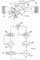
- the compressor is indicated generally at 10 and has an outflow tube 12 which is connected with and conveys pressurized refrigerant material to the condenser, indicated generally at 14.
- the condenser is connected by means of tubing to the expansion valve inlet port 16 which is connected to the expansion valve 18.
- the expansion valve inlet port 16 communicates with the expansion valve inlet orifice (not shown), which is connected by valving means to the expansion valve outlet port 22.
- the action of the expansion valve 18 and compressor 10 are controlled by the controller 20, by means of electronic signals sent between said controller and said valve and said compressor.
- the expansion valve outlet port 22 is connected by tubing means to the evaporator, indicated generally at 24. Said evaporator is connected by tubing means to the compressor inflow port 26; said tubing means may, but need not, pass through the expansion valve 18.
- FIG. 2 is a flow chart illustrating the preferred embodiment of the present invention. If the air-conditioning or refrigeration system is operating normally as denoted by reference numeral 32, the expansion valve is pulsed at its normal working frequency at step 34. If the system is being started up as a step 30, the compressor is energized at step 36 and the expansion valve remains in a closed or non-pulsing mode for an initial period of approximately one second at step 38. After the initial period of delay 38, the valve is pulsed at a high frequency rate equal to or greater than one and one-half times the normal working frequency at step 40. The high frequency pulsing is continued for approximately two seconds, or until approximately three seconds after the compressor was energized at step 42. After this period of high frequency pulsing, the valve pulse rate is reduced to its normal working frequency at step 34.
- Figure 3 is an alternative method of practicing the present invention. If the system is operating normally at step 50, the expansion valve is pulsed at its normal working frequency at step 52. If the system is being started up at step 54, the compressor is energized at step 56 and the expansion valve remains in a closed or non-pulsing mode for an initial period of approximately one second at step 58. After the initial period of delay 58, the valve begins pulsing at its normal working frequency 52 and continues at that rate thereafter.
- Figure 4 is a second alternative method of practicing the present invention. If the system is operating normally at step 60, the expansion valve is pulsed at its normal working frequency at step 62. If the system is being started up at step 64, the compressor is energized at step 66 and the expansion valve begins, with no period of delay, to pulse at a high frequency rate equal to or greater than one and one-half times the normal working frequency at step 68. The high frequency pulsing is continued for approximately three seconds at step 70. After this period of high frequency pulsing, the valve pulse rate is reduced to its normal working frequency 62.
- the present invention thus provides a method for minimizing or eliminating the audible flow noise which accompanies the short initial period of compressor operation by means of an initial period of delay and/or a short period of high frequency pulsing.
Landscapes
- Engineering & Computer Science (AREA)
- General Engineering & Computer Science (AREA)
- Mechanical Engineering (AREA)
- Physics & Mathematics (AREA)
- Thermal Sciences (AREA)
- Compression-Type Refrigeration Machines With Reversible Cycles (AREA)
- Air Conditioning Control Device (AREA)
- Magnetically Actuated Valves (AREA)
- Air-Conditioning For Vehicles (AREA)
- Compressor (AREA)
Applications Claiming Priority (2)
| Application Number | Priority Date | Filing Date | Title |
|---|---|---|---|
| US07/202,638 US4873836A (en) | 1988-06-06 | 1988-06-06 | Flow noise suppression for electronic valves |
| US202638 | 1988-06-06 |
Publications (2)
| Publication Number | Publication Date |
|---|---|
| EP0345545A2 true EP0345545A2 (fr) | 1989-12-13 |
| EP0345545A3 EP0345545A3 (fr) | 1991-04-10 |
Family
ID=22750707
Family Applications (1)
| Application Number | Title | Priority Date | Filing Date |
|---|---|---|---|
| EP19890109384 Withdrawn EP0345545A3 (fr) | 1988-06-06 | 1989-05-24 | Suppression de bruit d'écoulement pour des vannes électroniques |
Country Status (3)
| Country | Link |
|---|---|
| US (1) | US4873836A (fr) |
| EP (1) | EP0345545A3 (fr) |
| JP (1) | JPH0233578A (fr) |
Cited By (3)
| Publication number | Priority date | Publication date | Assignee | Title |
|---|---|---|---|---|
| WO1996006317A1 (fr) * | 1994-08-23 | 1996-02-29 | Bosch-Siemens Hausgeräte Gmbh | Circuiterie permettant d'actionner une electrovanne a excitation electrique |
| EP0692687A3 (fr) * | 1994-07-15 | 1998-03-18 | Sanyo Electric Co. Ltd | Appareil de refroidissement |
| EP2093508A1 (fr) * | 2008-02-20 | 2009-08-26 | LG Electronics Inc. | Climatisation et procédé de commande correspondant |
Families Citing this family (20)
| Publication number | Priority date | Publication date | Assignee | Title |
|---|---|---|---|---|
| US5303562A (en) * | 1993-01-25 | 1994-04-19 | Copeland Corporation | Control system for heat pump/air-conditioning system for improved cyclic performance |
| US7290989B2 (en) | 2003-12-30 | 2007-11-06 | Emerson Climate Technologies, Inc. | Compressor protection and diagnostic system |
| US7412842B2 (en) | 2004-04-27 | 2008-08-19 | Emerson Climate Technologies, Inc. | Compressor diagnostic and protection system |
| US7275377B2 (en) | 2004-08-11 | 2007-10-02 | Lawrence Kates | Method and apparatus for monitoring refrigerant-cycle systems |
| US8590325B2 (en) | 2006-07-19 | 2013-11-26 | Emerson Climate Technologies, Inc. | Protection and diagnostic module for a refrigeration system |
| US20080216494A1 (en) | 2006-09-07 | 2008-09-11 | Pham Hung M | Compressor data module |
| CN101617180B (zh) * | 2007-02-20 | 2012-01-11 | 大金工业株式会社 | 制冷剂循环及其控制方法 |
| US20090037142A1 (en) | 2007-07-30 | 2009-02-05 | Lawrence Kates | Portable method and apparatus for monitoring refrigerant-cycle systems |
| US8393169B2 (en) | 2007-09-19 | 2013-03-12 | Emerson Climate Technologies, Inc. | Refrigeration monitoring system and method |
| US9140728B2 (en) | 2007-11-02 | 2015-09-22 | Emerson Climate Technologies, Inc. | Compressor sensor module |
| US8160827B2 (en) | 2007-11-02 | 2012-04-17 | Emerson Climate Technologies, Inc. | Compressor sensor module |
| CN103597292B (zh) | 2011-02-28 | 2016-05-18 | 艾默生电气公司 | 用于建筑物的供暖、通风和空调hvac系统的监视系统和监视方法 |
| US9151526B2 (en) * | 2011-12-22 | 2015-10-06 | Lennox Industries Inc. | Method to control electronic expansion valve |
| US8964338B2 (en) | 2012-01-11 | 2015-02-24 | Emerson Climate Technologies, Inc. | System and method for compressor motor protection |
| US9480177B2 (en) | 2012-07-27 | 2016-10-25 | Emerson Climate Technologies, Inc. | Compressor protection module |
| US9310439B2 (en) | 2012-09-25 | 2016-04-12 | Emerson Climate Technologies, Inc. | Compressor having a control and diagnostic module |
| EP2971989A4 (fr) | 2013-03-15 | 2016-11-30 | Emerson Electric Co | Diagnostic et système de télésurveillance de chauffage, de ventilation et de climatisation |
| US9803902B2 (en) | 2013-03-15 | 2017-10-31 | Emerson Climate Technologies, Inc. | System for refrigerant charge verification using two condenser coil temperatures |
| US9551504B2 (en) | 2013-03-15 | 2017-01-24 | Emerson Electric Co. | HVAC system remote monitoring and diagnosis |
| WO2014165731A1 (fr) | 2013-04-05 | 2014-10-09 | Emerson Electric Co. | Systeme de pompe a chaleur a diagnostique de charge de fluide refrigerant |
Family Cites Families (11)
| Publication number | Priority date | Publication date | Assignee | Title |
|---|---|---|---|---|
| US3537272A (en) * | 1968-08-22 | 1970-11-03 | Hall Thermotank Intern Ltd | Expansion valve control including plural sensors |
| JPS57207773A (en) * | 1981-06-17 | 1982-12-20 | Taiheiyo Kogyo Kk | Method of controlling cooling circuit and its control valve |
| US4395886A (en) * | 1981-11-04 | 1983-08-02 | Thermo King Corporation | Refrigerant charge monitor and method for transport refrigeration system |
| US4548047A (en) * | 1981-11-11 | 1985-10-22 | Hitachi, Ltd. | Expansion valve |
| US4459819A (en) * | 1982-03-05 | 1984-07-17 | Emerson Electric Co. | Pulse controlled expansion valve and method |
| JPS5995350A (ja) * | 1982-11-22 | 1984-06-01 | 三菱電機株式会社 | 容量制御型冷凍サイクルの制御装置 |
| US4523435A (en) * | 1983-12-19 | 1985-06-18 | Carrier Corporation | Method and apparatus for controlling a refrigerant expansion valve in a refrigeration system |
| US4697431A (en) * | 1984-08-08 | 1987-10-06 | Alsenz Richard H | Refrigeration system having periodic flush cycles |
| JPH0755617B2 (ja) * | 1984-09-17 | 1995-06-14 | 株式会社ゼクセル | 車両用空気調和装置 |
| US4571951A (en) * | 1984-12-14 | 1986-02-25 | Vilter Manufacturing Corporation | Electronic control for expansion valve in refrigeration system |
| JPS6334459A (ja) * | 1986-07-29 | 1988-02-15 | 株式会社東芝 | 空気調和機 |
-
1988
- 1988-06-06 US US07/202,638 patent/US4873836A/en not_active Expired - Fee Related
-
1989
- 1989-05-24 EP EP19890109384 patent/EP0345545A3/fr not_active Withdrawn
- 1989-06-06 JP JP1143933A patent/JPH0233578A/ja active Pending
Cited By (4)
| Publication number | Priority date | Publication date | Assignee | Title |
|---|---|---|---|---|
| EP0692687A3 (fr) * | 1994-07-15 | 1998-03-18 | Sanyo Electric Co. Ltd | Appareil de refroidissement |
| WO1996006317A1 (fr) * | 1994-08-23 | 1996-02-29 | Bosch-Siemens Hausgeräte Gmbh | Circuiterie permettant d'actionner une electrovanne a excitation electrique |
| EP2093508A1 (fr) * | 2008-02-20 | 2009-08-26 | LG Electronics Inc. | Climatisation et procédé de commande correspondant |
| US8205463B2 (en) | 2008-02-20 | 2012-06-26 | Lg Electronics Inc. | Air conditioner and method of controlling the same |
Also Published As
| Publication number | Publication date |
|---|---|
| EP0345545A3 (fr) | 1991-04-10 |
| US4873836A (en) | 1989-10-17 |
| JPH0233578A (ja) | 1990-02-02 |
Similar Documents
| Publication | Publication Date | Title |
|---|---|---|
| US4873836A (en) | Flow noise suppression for electronic valves | |
| US6708510B2 (en) | Advanced refrigeration system | |
| US20060005552A1 (en) | Vehicle air-conditioning system | |
| EP0692687A2 (fr) | Appareil de refroidissement | |
| US6374624B1 (en) | On/off solenoid expansion device | |
| US6935125B2 (en) | Air conditioning system | |
| US5218836A (en) | Measuring evaporator load in an automotive air conditioning system for compressor clutch control using evaporator inlet temperature | |
| US20030070443A1 (en) | Refrigeration system with low-fuel shutdown | |
| US7836715B2 (en) | Air conditioner control logic for compressor noise and torque management | |
| JPH05296582A (ja) | 車両用空気調和装置 | |
| US5152151A (en) | Measuring evaporator load in an automotive air conditioning system for compressor clutch control | |
| US6367283B1 (en) | Three-stage electronically variable orifice tube | |
| US5105632A (en) | Refrigeration system having liquefied refrigerant control | |
| JPS6227817Y2 (fr) | ||
| JPH06174319A (ja) | 車両用空調装置 | |
| JP2000094953A (ja) | 自動車用冷房装置 | |
| JP2006132800A (ja) | 冷凍サイクル装置 | |
| JPS6315513B2 (fr) | ||
| JP3257098B2 (ja) | 冷凍サイクル | |
| US6397995B1 (en) | Method for controlling a clutch for an engine-powered system in an automotive vehicle | |
| JPH08207554A (ja) | 自動車用冷房装置 | |
| JP3291886B2 (ja) | 空調装置およびその制御方法 | |
| JPS61213446A (ja) | カ−エアコン冷凍サイクル | |
| JP2003182348A (ja) | 自動車用空調装置 | |
| JPS60151118A (ja) | 自動車用空気調和機 |
Legal Events
| Date | Code | Title | Description |
|---|---|---|---|
| PUAI | Public reference made under article 153(3) epc to a published international application that has entered the european phase |
Free format text: ORIGINAL CODE: 0009012 |
|
| AK | Designated contracting states |
Kind code of ref document: A2 Designated state(s): DE FR GB IT |
|
| PUAL | Search report despatched |
Free format text: ORIGINAL CODE: 0009013 |
|
| AK | Designated contracting states |
Kind code of ref document: A3 Designated state(s): DE FR GB IT |
|
| STAA | Information on the status of an ep patent application or granted ep patent |
Free format text: STATUS: THE APPLICATION IS DEEMED TO BE WITHDRAWN |
|
| 18D | Application deemed to be withdrawn |
Effective date: 19911011 |