EP0345555A2 - Verriegelungsmechanismus für Hinterräder-Lenkapparat - Google Patents
Verriegelungsmechanismus für Hinterräder-Lenkapparat Download PDFInfo
- Publication number
- EP0345555A2 EP0345555A2 EP89109473A EP89109473A EP0345555A2 EP 0345555 A2 EP0345555 A2 EP 0345555A2 EP 89109473 A EP89109473 A EP 89109473A EP 89109473 A EP89109473 A EP 89109473A EP 0345555 A2 EP0345555 A2 EP 0345555A2
- Authority
- EP
- European Patent Office
- Prior art keywords
- rear wheels
- locking
- steering
- movement
- rack
- Prior art date
- Legal status (The legal status is an assumption and is not a legal conclusion. Google has not performed a legal analysis and makes no representation as to the accuracy of the status listed.)
- Withdrawn
Links
Images



Classifications
-
- B—PERFORMING OPERATIONS; TRANSPORTING
- B62—LAND VEHICLES FOR TRAVELLING OTHERWISE THAN ON RAILS
- B62D—MOTOR VEHICLES; TRAILERS
- B62D7/00—Steering linkage; Stub axles or their mountings
- B62D7/06—Steering linkage; Stub axles or their mountings for individually-pivoted wheels, e.g. on king-pins
- B62D7/14—Steering linkage; Stub axles or their mountings for individually-pivoted wheels, e.g. on king-pins the pivotal axes being situated in more than one plane transverse to the longitudinal centre line of the vehicle, e.g. all-wheel steering
- B62D7/148—Steering linkage; Stub axles or their mountings for individually-pivoted wheels, e.g. on king-pins the pivotal axes being situated in more than one plane transverse to the longitudinal centre line of the vehicle, e.g. all-wheel steering provided with safety devices
Definitions
- the present invention relates to an apparatus for steering the rear wheels of a vehicle.
- the present invention relates to an apparatus for selectively locking the rear wheels to prevent turning of the rear wheels.
- a steering system for such a vehicle is disclosed in U.S. Patent No. 4,645,025.
- the steering system disclosed in U.S. Patent No. 4,645,025 includes a steering gear for turning the rear wheels in response to steering the front wheels.
- the steering gear includes a housing supporting a rack member for axial movement.
- a pinion has teeth in meshing engagement with teeth on the rack member.
- the pinion is rotated by an electric motor to axially move the rack member to thereby turn the rear wheels.
- the direction and amount of movement of the rack member is determined by a controller and is a function of vehicle speed and the direction and amount of steering of the front wheels.
- the rack member is spring biased to a position in which the rear wheels are in a straight-ahead position. There is no positive locking of the rear wheels in the straight-ahead position.
- U.S. Patent No. 4,671,523 discloses a steering system for steering the front wheels and rear wheels of a vehicle.
- the steering system includes a steering gear for the rear wheels.
- the steering gear for the rear wheels includes an electric motor which drives a pinion connected with a rack member. When the rack member moves, the rear wheels turn.
- the rack member has a notch.
- a locking member is spring biased into the notch to block movement of the rack member and maintain the rear wheels in a straight-ahead position. Pressurized fluid moves the locking member to disengage the rack member.
- the present invention is directed to a steering system for a vehicle having steerable front wheels and steerable rear wheels.
- the steering system includes a steering gear for the rear wheels.
- the steering gear has a movable member connected with the rear wheels to steer the rear wheels upon movement of the member.
- the member is moved by power assist means in response to steering of the front wheels. Movement of the member is blocked in response to a failure of the power assist means.
- the member is a rack member of a rack and pinion steering gear.
- the power assist means is an electric motor for axially moving the rack member.
- a pinion has teeth in meshing engagement with teeth on the rack member.
- the pinion is rotatable in response to axial movement of the rack member.
- a collar member is connected to the pinion and has a notch therein.
- a locking member is movable into the notch in the collar to block rotation of the collar and pinion. Blocking rotation of the pinion thereby blocks axial movement of the rack member and thus, turning of the rear wheels.
- the position of the locking member is controlled by a solenoid.
- the solenoid When the solenoid is energized, the locking member moves to a position disengaged from the notch in the collar. When the locking member is disengaged from the notch in the collar, rotation of the pinion is permitted thereby allowing axial movement of the rack member and turning of the rear wheels.
- a spring moves the locking member toward the collar.
- the steering system also includes a switch for manually selecting either front wheel only steering or combined front and rear wheel steering.
- the switch When the switch is moved to a position selecting combined front and rear wheel steering, the solenoid is energized to move the locking member to the position permitting turning of the rear wheels.
- the present invention may be embodied in a number of different vehicle steering systems for steering the front wheels and the rear wheels of a vehicle.
- the present invention is illustrated in Fig. 1 as embodied in a steering system 22 for a vehicle having steerable front wheels F and steerable rear wheels R.
- the steering system 22 includes a steering gear 24 for steering the front wheels F and a steering gear 26 for steering the rear wheels R.
- the steering gears 24, 26 could be identical rack and pinion steering gears each having an electric motor for power assist. However, the steering gears 24, 26 do not have to be identical. Also, either the steering gear for the front wheels F and/or the steering gear for the rear wheels R could be fluid power assist steering gears.
- the steering gear 24 for the front wheels F is similar in design and operation to the steering gear disclosed in U.S. Patent No. 4,666,014 which is fully incorporated herein by reference.
- the steering gear 24 for the front wheel F is connected to a manually operated steering wheel SW, as is known.
- a torque sensor TS is connected between the steering wheel SW and the steering gear 24 for the front wheels F.
- the torque sensor TS generates a signal indicative of the magnitude and direction of the torque applied thereto and communicates the signal to a controller 42.
- the controller 42 processes the signal from the torque sensor TS and applies electric power to an electric motor 32 of the steering gear 24 for the front wheels F.
- the electric motor 32 axially moves a rack member (not shown) connected with the front wheels F to steer the front wheels in a direction corresponding to the direction that the steering wheel SW is turned and to an extent until no torque is sensed by the torque sensor TS.
- a position sensor 46 connected with the rack member of the steering gear 24 senses the axial position of the rack member relative to an initial position of the rack member corresponding to a straight-ahead position of the front wheels F.
- the position sensor 46 generates a signal corresponding to the direction and amount of movement from the initial position and communicates the signal to the controller 42.
- the position sensor 46 is preferably a known linear voltage differential transformer (LVDT).
- the controller 42 monitors a speed sensor 62 which senses vehicle speed.
- the controller 42 also monitors the position of a four wheel steering select switch 64.
- the switch 64 is manually movable to select between front wheel only steering and combined front and rear wheel steering.
- the controller 42 signals a locking mechanism 66 connected to the rear wheel steering gear 26 to unlock the steering gear 26 and permit steering movement of the rear wheels R.
- the controller 42 applies electric power to an electric motor 82 of the rear wheel steering gear 26 to turn the rear wheels R in a desired direction and to an extent as determined by a control program stored in the controller as a function of vehicle speed. For example, if combined front and rear wheel steering is selected at the switch 64, and the vehicle is moving at a speed below a predetermined speed, the rear wheels R will be steered in an opposite direction relative to the direction that the front wheels F are steered. If the vehicle is travelling above the predetermined speed, the rear wheels R will be steered in the same direction as the front wheels F.
- the locking mechanism 66 locks the rear wheels R from angular movement when front wheel only steering is selected by the switch 64 or when power assist to the rear wheel steering gear is lost.
- a steering position sensor 84 for the rear wheel steering gear 26 is similar to the sensor 46 for the front wheel steering gear 24.
- the sensor 84 senses the position of a rack member 102 (Fig. 2), which is connected with the rear wheels R, relative to an initial position corresponding to the straight-ahead position of the rear wheels.
- the sensor 84 generates a signal indicative of the direction and amount of movement of the rack member 102 from the initial position and communicates the signal to the controller 42.
- the controller 42 processes the information from the sensor 84 to insure that the position of the rear wheels R corresponds to a desired position (within a tolerance band) determined by the controller 42.
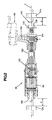
- the steering gear 26 (Fig. 2) for the rear wheels R is similar in design and operation to the steering gear disclosed in U.S. Patent No. 4,666,014, referred to above.
- the steering gear 26 includes a housing 100 supporting the rack member 102 for axial movement in a direction along a longitudinal central axis A of the rack member.
- a plurality of rack teeth 112 are formed on the rack member 102.
- a pinion 104 is supported for rotation about its longitudinal central axis B by the housing 100.
- the pinion 104 has a plurality of pinion teeth 114 for meshing engagement with the rack teeth 112 on the rack member 102.
- the pinion 104 rotates about the axis B in response to movement of the rack member 102 along the axis A.
- the electric motor 82 is connected with the rack member 102 through a ball nut drive 122.
- the rack member 102 moves axially relative to the housing 100 along the axis A and the pinion rotates about the axis B.
- a pair of stops 124 are connected to axially opposite end portions of the rack member 102.
- Each of the stops 124 is an annular member which is clamped to the rack member 102.
- the stops 124 are located outside of the housing 100 and are spaced away from the housing a distance D.
- the rack member 102 moves to the left along the axis A, as viewed in Fig. 2, an amount equal to the distance D, the right stop 124 engages an end 126 of the housing 100 to block further movement of the rack member to the left.
- the left stop 124 blocks movement of the rack member 102 to the right.
- the distance D that the stops 124 are spaced from the respective ends 126, 128 of the housing 100 limits the angular movement of the steerable rear wheels R to a displacement of preferably not more than five degrees in either direction from the straight-ahead postion.
- the locking mechanism 66 includes a housing 142 (Fig. 3) connected to the housing 100 by fasteners 144.
- a collar 146 is received in an opening 148 extending through the housing 142.
- the collar 146 is ring shaped and connected to the pinion 104 by a known spline connection 152. Thus, the collar 146 rotates with the pinion 104.
- the collar 146 has a surface defining a notch 162 (best seen in Fig. 5) in its outer circumference.
- the notch 162 is located in the collar 146 in a position for receiving a locking portion 166 of a locking member 164 when the rear wheels R are in the straight-ahead position to lock the rear wheels in the straight-ahead position.
- the locking member 164 (Fig. 4) is supported at one end for pivotal movement by a pin 182 received in the housing 142.
- the locking member 164 is pivotable about the axis of the pin 182 between locking and unlocking positions.
- the end portion 166 of the locking member 164 is received in the notch 162 in the collar 146.
- rotation of the collar 146 is blocked.
- rotation of the pinion 104, axial movement of the rack member 102 and turning movement of the rear wheels R are also blocked.
- the end portion 166 of the locking member is disengaged from notch 162 in the collar 146, rotation of the collar 146 and pinion 104, axial movement of the rack member 102 and turning of the rear wheels R are possible.
- the collar 146 has an outer diameter D1 (Fig. 3) which is preferably at least three times the diameter D2 of the pitch circle of the teeth 114 on the pinion 104.
- the notch 162 is spaced from the axis B of the pinion 104 resulting in a minimum effective lever arm L1 (Fig. 3) through which the locking portion 166 of the locking member 164 acts on the pinion 104.
- the rack member 102 also acts on the pinion 104 through another lever arm L2 which is shorter than the lever arm L1. Because of the differences in the lengths of the lever arms L1 and L2, forces acting on the pinion 104 through the lever arm L1 have a mechanical advantage.
- the force applied to the collar 146 to prevent the pinion 104 from rotating may be smaller than the force applied to the pinion 104 acting to rotate the pinion.
- the locking portion 166 of the locking member 164 does not require the size nor strength that would be required if it engaged a notch in the pinion 104 or in the rack member 102.
- the position of the locking member 164 is controlled by a solenoid 202.
- the solenoid 202 (Fig. 6) is connected to the housing 142 of the locking mechanism 66.
- the solenoid 202 includes a coil 204 and a plunger 206 which is axially movable within the solenoid along a longitudinal central axis C of the solenoid upon the application of electrical power to the coil.
- the controller 42 controls the application of electrical power to the solenoid 202.
- a spring 222 normally biases the plunger 206 downwardly, to the position illustrated in Figs. 4, 6 and 7, when electrical power is not applied to the solenoid 202.
- a cam member 224 is connected to the plunger 206.
- the cam member 224 includes a frustoconical tapered portion 242 and a cylindrical body portion 244.
- a pilot shaft 246 is connected to the cam member 224 and extends along the axis C.
- the pilot shaft 246 is received in a bearing 248 supported in a bore 250 in a lower portion 260 of the housing 142.
- the bearing 248 includes a plurality of ball bearings 252 supported in a tubular cage.
- the pilot shaft 246 and bearing 248 enable the cam member 224 to move axially along the axis C with relatively little frictional resistance.
- a disk-shaped cam follower 262 is received in a portion 264 of the locking member 164.
- the follower 262 engages both the cylindrical body portion 244 of the cam member 224 and the locking member 164.
- the force of the spring 222 is greater than the force of the spring 184 and, thus, the locking member 164 is forced by spring 222 in a direction away from the axis C of the solenoid 202 toward its locking position.
- the locking member 164 is biased by the spring 222 toward its locking position.
- the plunger 206 moves the cam member 224 and the pilot shaft 246 upwardly along the axis C from the position illustrated in Figs. 6 and 7 to the position illustrated in Fig. 8.
- the cam follower 262 engages the frustoconical tapered portion 242 of the cam member 224 which permits the end portion 166 of the locking arm 164 to pivot toward the axis C of the solenoid 202 and away from the collar 146 until the cam follower engages the pilot shaft 246.
- the locking member 164 pivots about the pin 182 away from the collar 146, from its locking position illustrated in Fig. 4 to its unlocking position illustrated in Fig. 5, the locking portion 166 disengages the notch 162.
- the controller 42 applies electrical power to the solenoid 202 in certain situations. For example, the controller 42 applies electrical power to the solenoid 202 when the switch 64 is moved to the position selecting combined front and rear wheel steering. When the switch 64 is moved to a position in which front wheel only steering is selected, the controller 42 does not apply electrical power to the solenoid 202.
- the solenoid 202 when the solenoid 202 is de-energized, the locking portion 166 of the locking member 164 is biased toward the collar 146 by the spring 222 and cam member 224. When the rear wheels R are in the straight-ahead position, the locking portion 166 of the locking member 164 extends into the notch 162 in the collar 146 when the solenoid is de-energized to lock the rear wheels R in the straight-ahead position.
- the notch 162 is not aligned with the locking portion 166 of the locking member 164 and the locking portion engages the periphery of the collar 146.
- the notch 162 will not receive the locking portion 166 of the locking member 164 until the rear wheels R move to a straight-ahead position and the notch 162 is aligned with the locking portion 166 of the locking member 164.
- the geometry of the suspension system i.e. the camber and caster of the rear wheels R) is such that the rear wheels R will move to the straight-ahead position in the absence of power assist.
- the rear wheels R When a failure to the motor 82 occurs or loss of electrical power for driving the motor occurs in the absence of the locking mechanism 66 embodying the present invention, the rear wheels R would tend to move uncontrollably between their turning limits.
- the controller 42 detects such a failure in the motor 82 or a failure in the power supplied to the motor, the controller shuts off electrical power to the solenoid 202 to lock the rear wheels R in the straight-ahead position.
- the solenoid if the controller 42 or solenoid 202 fails, the solenoid is de-energized and the locking member 164 is normally biased to its locking position.
- the locking mechanism 66 the rear wheels R are locked in the straight-ahead position in the event of a failure in the motor 82, controller 42 or solenoid 202.
Landscapes
- Engineering & Computer Science (AREA)
- Chemical & Material Sciences (AREA)
- Combustion & Propulsion (AREA)
- Transportation (AREA)
- Mechanical Engineering (AREA)
- Steering-Linkage Mechanisms And Four-Wheel Steering (AREA)
Applications Claiming Priority (2)
| Application Number | Priority Date | Filing Date | Title |
|---|---|---|---|
| US203682 | 1980-11-03 | ||
| US07/203,682 US4856606A (en) | 1988-06-07 | 1988-06-07 | Lock mechanism for rear wheel steer apparatus |
Publications (2)
| Publication Number | Publication Date |
|---|---|
| EP0345555A2 true EP0345555A2 (de) | 1989-12-13 |
| EP0345555A3 EP0345555A3 (de) | 1990-11-07 |
Family
ID=22754893
Family Applications (1)
| Application Number | Title | Priority Date | Filing Date |
|---|---|---|---|
| EP19890109473 Withdrawn EP0345555A3 (de) | 1988-06-07 | 1989-05-26 | Verriegelungsmechanismus für Hinterräder-Lenkapparat |
Country Status (3)
| Country | Link |
|---|---|
| US (1) | US4856606A (de) |
| EP (1) | EP0345555A3 (de) |
| JP (1) | JPH0257480A (de) |
Cited By (5)
| Publication number | Priority date | Publication date | Assignee | Title |
|---|---|---|---|---|
| EP0470424A1 (de) * | 1990-08-07 | 1992-02-12 | FIAT AUTO S.p.A. | Vorrichtung zum Begrenzen des Einschlagwinkels von Fahrzeugrädern |
| WO1992012888A1 (de) * | 1991-01-29 | 1992-08-06 | Zahnradfabrik Friedrichshafen Ag | Elektromotorische antriebseinheit zur betätigung einer elektromechanischen hinterradlenkung von kraftfahrzeugen |
| US5261500A (en) * | 1991-01-18 | 1993-11-16 | General Motors Corporation | Four-wheel steering locking mechanism for a motor vehicle |
| DE4334279A1 (de) * | 1993-10-08 | 1995-04-13 | Claas Ohg | Allrad-Lenkungssteuerung |
| FR2884794A1 (fr) * | 2005-04-26 | 2006-10-27 | Renault Sas | Dispositif de centrage de train directionnel de vehicule reversible |
Families Citing this family (16)
| Publication number | Priority date | Publication date | Assignee | Title |
|---|---|---|---|---|
| US5076382A (en) * | 1989-06-23 | 1991-12-31 | Trw Inc. | Method and apparatus for steering a vehicle |
| US5238077A (en) * | 1989-06-23 | 1993-08-24 | Trw Inc. | Method and apparatus for steering a vehicle |
| JPH03112784A (ja) * | 1989-09-27 | 1991-05-14 | Mazda Motor Corp | 車両の後輪操舵装置 |
| ES2024081A6 (es) * | 1989-11-02 | 1992-02-16 | Gutierrez De Cepeda Juan | Sistema de cuatro ruedas directrices elctronico con mecanismo de seguridad para vehiculos. |
| DE69115621T2 (de) * | 1990-09-25 | 1996-06-20 | Mazda Motor | Hinterradlenkungsvorrichtung |
| US5259475A (en) * | 1992-04-29 | 1993-11-09 | Fmc Corporation | Front wheel and front and rear wheel steering system |
| US7401677B2 (en) * | 2002-02-13 | 2008-07-22 | Trw Inc. | Self-centering steering system |
| US8534414B2 (en) * | 2003-07-09 | 2013-09-17 | Trw Automotive U.S. Llc | Steering apparatus for a vehicle having front and rear steerable wheels |
| DE10341808A1 (de) | 2003-09-10 | 2005-04-28 | Jungheinrich Moosburg Gmbh | Lenksysteme mit Lenkwinkelbegrenzung |
| US20060254237A1 (en) * | 2005-05-16 | 2006-11-16 | Ricketts Jonathan E | Agricultural combine |
| GB0624925D0 (en) * | 2006-12-14 | 2007-06-06 | One80 Ltd | Vehicle having steerable rear wheels |
| GB2461290B (en) * | 2008-06-26 | 2012-12-05 | One80 Ltd | Rear wheel steering system |
| DE102010052546A1 (de) * | 2010-11-25 | 2012-05-31 | Audi Ag | Lenkeinrichtung |
| US10421486B2 (en) | 2017-05-12 | 2019-09-24 | Cnh Industrial America Llc | Four wheel steering with lock assembly |
| JP2018202923A (ja) * | 2017-05-31 | 2018-12-27 | 株式会社東海理化電機製作所 | ロック装置 |
| DE102019219392A1 (de) * | 2019-12-11 | 2021-06-17 | Robert Bosch Gmbh | Steer-by-Wire Lenksystem |
Family Cites Families (7)
| Publication number | Priority date | Publication date | Assignee | Title |
|---|---|---|---|---|
| DE2055364C3 (de) * | 1970-11-11 | 1981-06-11 | Daimler-Benz Ag, 7000 Stuttgart | Schaltgetriebe für die Lenkung von Fahrzeugrädern, insbesondere von Kraftfahrzeugen mit Mehrachslenkung |
| GB2157242B (en) * | 1984-02-28 | 1988-07-27 | Mitsubishi Motors Corp | Rear wheel steering apparatus |
| DE3413007A1 (de) * | 1984-04-06 | 1985-10-17 | Audi AG, 8070 Ingolstadt | Lenkeinrichtung fuer ein kraftfahrzeug |
| JPS61184184A (ja) * | 1985-02-08 | 1986-08-16 | ヤマハ発動機株式会社 | 二輪車の前後輪操向装置 |
| JPS61202977A (ja) * | 1985-03-06 | 1986-09-08 | Jidosha Kiki Co Ltd | 車両の操舵装置 |
| JPS62218228A (ja) * | 1986-03-19 | 1987-09-25 | Toyota Motor Corp | 四輪駆動装置の制御方法 |
| FR2610275B1 (fr) * | 1987-02-03 | 1990-09-07 | Peugeot | Dispositif de commande de braquage des roues arriere d'un vehicule et vehicule automobile equipe de ce dispositif |
-
1988
- 1988-06-07 US US07/203,682 patent/US4856606A/en not_active Expired - Lifetime
-
1989
- 1989-05-26 EP EP19890109473 patent/EP0345555A3/de not_active Withdrawn
- 1989-06-07 JP JP1145013A patent/JPH0257480A/ja active Pending
Cited By (5)
| Publication number | Priority date | Publication date | Assignee | Title |
|---|---|---|---|---|
| EP0470424A1 (de) * | 1990-08-07 | 1992-02-12 | FIAT AUTO S.p.A. | Vorrichtung zum Begrenzen des Einschlagwinkels von Fahrzeugrädern |
| US5261500A (en) * | 1991-01-18 | 1993-11-16 | General Motors Corporation | Four-wheel steering locking mechanism for a motor vehicle |
| WO1992012888A1 (de) * | 1991-01-29 | 1992-08-06 | Zahnradfabrik Friedrichshafen Ag | Elektromotorische antriebseinheit zur betätigung einer elektromechanischen hinterradlenkung von kraftfahrzeugen |
| DE4334279A1 (de) * | 1993-10-08 | 1995-04-13 | Claas Ohg | Allrad-Lenkungssteuerung |
| FR2884794A1 (fr) * | 2005-04-26 | 2006-10-27 | Renault Sas | Dispositif de centrage de train directionnel de vehicule reversible |
Also Published As
| Publication number | Publication date |
|---|---|
| EP0345555A3 (de) | 1990-11-07 |
| US4856606A (en) | 1989-08-15 |
| JPH0257480A (ja) | 1990-02-27 |
Similar Documents
| Publication | Publication Date | Title |
|---|---|---|
| US4856606A (en) | Lock mechanism for rear wheel steer apparatus | |
| US6896089B2 (en) | Steer-by-wire steering system with rotation limiter | |
| US6899196B2 (en) | Driver interface system for steer-by-wire system | |
| US6360841B1 (en) | Power steering mechanism with magnetoelastic torsion bar | |
| EP1138576B1 (de) | Lenkhilfsregelung mit Lineardifferential | |
| US20170151975A1 (en) | Vehicle Steering System | |
| EP1250251B1 (de) | Kupplung für eine steer-by-wire-lenkanlage | |
| EP0975507B1 (de) | Hilfskraftlenkung mit hydraulischer hilfskraftunterstützung | |
| EP1486397B1 (de) | Ausfallsichere Lenkanlage für ein Kraftfahrzeug | |
| US6938720B2 (en) | Steering input devices for steer-by-wire systems | |
| WO2005009823A2 (en) | Steering apparatus for a vehicle having front and rear steerable wheels | |
| EP1091868B1 (de) | Hilfskraftlenkung mit hydraulischer hilfskraftunterstützung | |
| EP1474323A1 (de) | Selbstzentrierendes lenksystem | |
| US4987963A (en) | Steering gear for the roadwheels of a vehicle | |
| US5289891A (en) | Rear-wheel steering apparatus for wheeled vehicle | |
| JPH06107218A (ja) | 後輪操舵装置の中立復帰機構 | |
| EP0279034B1 (de) | Hilfskraftverstärkte Zahnstangenlenkung mit Mittenantrieb | |
| US5261500A (en) | Four-wheel steering locking mechanism for a motor vehicle | |
| US4648614A (en) | Steering system in wheeled vehicle | |
| JP5892369B2 (ja) | 後輪操舵装置 | |
| US12466464B2 (en) | Steering rack bending limiter and steering assembly therewith | |
| CA2276554C (en) | Rear wheel steering device having fail-safe features | |
| US6752237B2 (en) | Rear wheel steering apparatus | |
| US5131485A (en) | Steering apparatus for steering rear wheels of automotive vehicle | |
| US4813694A (en) | Rear wheel steering drive mechanism |
Legal Events
| Date | Code | Title | Description |
|---|---|---|---|
| PUAI | Public reference made under article 153(3) epc to a published international application that has entered the european phase |
Free format text: ORIGINAL CODE: 0009012 |
|
| AK | Designated contracting states |
Kind code of ref document: A2 Designated state(s): DE FR GB IT |
|
| PUAL | Search report despatched |
Free format text: ORIGINAL CODE: 0009013 |
|
| AK | Designated contracting states |
Kind code of ref document: A3 Designated state(s): DE FR GB IT |
|
| 17P | Request for examination filed |
Effective date: 19901211 |
|
| 17Q | First examination report despatched |
Effective date: 19920521 |
|
| STAA | Information on the status of an ep patent application or granted ep patent |
Free format text: STATUS: THE APPLICATION IS DEEMED TO BE WITHDRAWN |
|
| 18D | Application deemed to be withdrawn |
Effective date: 19931019 |