EP0345631A2 - Pièce de fixation et méthode pour laboratoire usinant des lentilles additionnelles progressivement asphériques - Google Patents
Pièce de fixation et méthode pour laboratoire usinant des lentilles additionnelles progressivement asphériques Download PDFInfo
- Publication number
- EP0345631A2 EP0345631A2 EP89109898A EP89109898A EP0345631A2 EP 0345631 A2 EP0345631 A2 EP 0345631A2 EP 89109898 A EP89109898 A EP 89109898A EP 89109898 A EP89109898 A EP 89109898A EP 0345631 A2 EP0345631 A2 EP 0345631A2
- Authority
- EP
- European Patent Office
- Prior art keywords
- lens
- shim
- blocking
- cross members
- progressive
- Prior art date
- Legal status (The legal status is an assumption and is not a legal conclusion. Google has not performed a legal analysis and makes no representation as to the accuracy of the status listed.)
- Granted
Links
Images

Classifications
-
- B—PERFORMING OPERATIONS; TRANSPORTING
- B24—GRINDING; POLISHING
- B24B—MACHINES, DEVICES, OR PROCESSES FOR GRINDING OR POLISHING; DRESSING OR CONDITIONING OF ABRADING SURFACES; FEEDING OF GRINDING, POLISHING, OR LAPPING AGENTS
- B24B13/00—Machines or devices designed for grinding or polishing optical surfaces on lenses or surfaces of similar shape on other work; Accessories therefor
- B24B13/005—Blocking means, chucks or the like; Alignment devices
-
- G—PHYSICS
- G02—OPTICS
- G02C—SPECTACLES; SUNGLASSES OR GOGGLES INSOFAR AS THEY HAVE THE SAME FEATURES AS SPECTACLES; CONTACT LENSES
- G02C7/00—Optical parts
- G02C7/02—Lenses; Lens systems ; Methods of designing lenses
- G02C7/06—Lenses; Lens systems ; Methods of designing lenses bifocal; multifocal ; progressive
- G02C7/061—Spectacle lenses with progressively varying focal power
Definitions
- This invention relates to the field of ophthalmic lenses. More particularly, this invention relates to apparatus and a method for use in blocking lenses for machine processing of lenses.
- Presbyopia is the loss of accomodation of the eye with age. It is classically treated by means of bifocal or trifocal spetacle lenses. Progressive lenses are the modern alternative to bifocal and trifocal lenses. Progressive lenses provide a continuous gradient of optical powers, ranging from the power required for viewing distant objects to that required for near objects. Because of the unbroken visual field provided by such lenses, many patients consider progressive lenses to be optically superior to the bifocal or trifocal lenses. Moreover, because of the absence of visible dividing lines, progressive lenses offer a distinct cosmetic advantage over conventional multifocals.
- the progressive surface of a progressive lens ordinarily comprises the convex side of the lens.
- the sphero-cylindrical surface required to accomodate the patient's prescription is ground into the concave side of the lens.
- the generating grinding, and polishing of the concave surface is a standard processing operation of the ophthalmic prescription laboratory.
- the lens Before the concave side of a lens can be surfaced, the lens must undergo a "blocking" operation.
- the operation consists of mounting a molded metal disk, or “block”, on the convex side of the lens.
- the block provides an accurate mechanical reference surface for holding the lens in the chuck of the lens curve generator.
- the block consists of a low melting point alloy which is molded to shape directly against the convex surface of the lens to be blocked.
- the molding operation requires that the lens be held accurately against a reference ring, inside of which the melted alloy is poured and eventually solidifies.
- the reference ring is a hollow right circular cylinder.
- the lens is placed against the blocking ring in such a way that only the distance portion of the lens actually makes contact with the inside edge of the ring. The reading half of the lens does not make contact with the ring. If the distance portion of the progressive side of the lens is essentially spherical, then accurate seating of the lens against the blocking ring is assured and the lens may be blocked exactly as if the lens were an ordinary bifocal or trifocal. If, however, the distance portion is aspherical, as is the case in the most advanced progressive-lens designs, then the lens may rock when placed against the blocking ring, and accurate seating against the ring becomes problematical. This can result in improper blocking and, subsequently, an improper generating operation leading to unwanted prism at the distance fitting center.
- the asphericity is such that the average curvature in a horizontal merdian through the distance fitting center is greater than the average curvature in the distance portion half of a vertical merdian through the fitting center. That is, the distance portion of the progressive surface is slightly egg-shaped, the axis of the egg being vertical. It is clear that a surface of this shape cannot be mated to the end of a hollow right circular cylinder without rocking.
- the purpose of the present invention is to provide an apparatus and a method to address and solve the problem of blocking a progressive lens that has an aspherical distance portion.
- a special "T" shaped shim is provided, which is pressed before blocking onto the distance portion of the lens, and the shim provides stable, three point contact with the standard cylindrical blocking ring.
- the shim is made of a flexible material such as vinyl.
- the shim should be as thin as possible to prevent leackage of the molten material (usually metal) from the space created between the lens and the blocking ring, consistent with the requirement that it be thick enough to compensate for the maximum asphericity of the lens.
- a thickness of approximately 0.35 mm is generally sufficient to compensate for the highest addition values of the lens, where the degree of asphericity is greatest.
- the shim has the general shape of an inverted "T".
- T has the general shape of a "T", and it is mounted in an inverted position on the lens.
- the horizontal member of the T coincides with the 0-180° of the lens, and the vertical member points toward the upper edge of the distance portion of the lens.
- the intersection point of the T coincides precisely with the distance fitting center. All three legs of the T must extend beyond the diameter of the blocking ring.
- the two horizontal legs of the T need not be colinear. Instead their angles with the vertical leg may exceed 90°, for greater mechanical stability and uniformity of lens edge thickness.
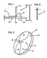
- Shim 10 is generally "T" shaped member having a first portion 12 which might be referred to as a base member, and a cross member 14 made up of left and right segments 16 and 18. Each of the arms 16, 18 has an enlarged inboard segment adjacent to the base 12 and a smaller outboard segment.
- base portion 12 might also be referred to as a vertical member
- cross member 14 might also be referred to as a horizontal member, but it will be understood that the shim is not limited to being used with those members in vertical and horizontal orientations.
- Shim 10 is shown in an inverted T position, since that is the general orientation in which it is to be mounted on a lens for processing of the lens.
- Shim 10 is made of a flexible material such as vinyl, and it has a thickness "t" (see Figure 2) which is sufficient to compensate for the maximum asphericity of the lens on which it is to be mounted. Generally, a thickness "t" of about 0.35 mm will be sufficient for most cases.
- Shim 10 has various alignment indicia thereon for aligning the shim on a lens.
- These alignment indicia include a series of three circles 20, 22, 24 which are arrayed on a straight line. The centers of circles 20, 22 and 24 are intended to lie on and align with the 0-180° line (line 34) of the lens.
- the alignment indicia also include a "T" marking 26, the intersection point of which is intended to coincide precisely with the distance fitting center (36) of the lens.
- lens 28 has an upper distance portion (DP) 30, a lower reading portion (RP) 32 and an intermediate portion (IP) therebetweeen.
- DP distance portion
- RP lower reading portion
- IP intermediate portion
- the preprocessing lens is marked with a 0-180° line 34, and a "T" whose intersection point defines the distance fitting center.
- the line may also have other indicia for use in processing.
- the convex surface of a progressive lens may be aspherical in the distance portion, and this asphericity results in problems in mounting a block on the lens for processing of the lens. Specifically, the asphericity results in the block being unstable or rocking, so that it cannot be stably held against the convex surface of the lens for the purpose of securing the block to the lens (e.g., by a low melting point alloy, sometimes called low lead, as is well known in the art).
- a low melting point alloy sometimes called low lead
- Figure 4 shows the transparent shim 10 of the present invention mounted on the lens 28 in the distance portion of the lens.
- the circular indicia 20, 22, 24 on shim 10 are arrayed with their centers along 0-180° line 34.
- the "T" indicia 26 on shim 10 precisely overlaps the "T” indicia 36 on the lens, so that the intersection of "T” indicia 26 is at the distance filling center of the lens.
- the circle 22 aligns with the vertical part of indicia 26 so that circle 22 is at the blocking center of the lens.
- the base member 12 of shim 10 extends toward the upper edge of the distance portion of the lens.
- the side of "T" 10 in contact with the convex surface of lens 28 is coated with a pressure sensitive releasable adhesive so that the shim can be adhered to the lens for use and then removed after the lens is processed. It should also be noted that to protect the convex surface of lens 28 from mechanical abuse, it is standard practice to cover the surface of the lens completely with a transparent protective tape prior to blocking. Blocking shim 10 is applied over, not under, such protective tape. The release adhesive on one side of shim 10 ensures adherence of the shim to the free side of the protective tape.
- the phantom line 40 in Figure 4 shows the position of the inner diameter of a blocking ring 38 (see Figure 5) which would be mounted on lens 28 for processing of the lens.
- All three members of the shim T i.e., base 12 and cross arms 16 and 18 extend outboard beyond the outer diameter of the blocking ring.
- the inner diameter 42 of the block ring has three stable points of contact (i.e., base 12, arm 16 and arm 18), and the block does not rock. Accordingly, the block can be held stably on the lens while the block is adhered to the lens (e.g., by introducing the molten lead alloy into the block cavity).
- Figure 5 shows, in side view, the distance portion of the lens 28, with the shim 10 applied thereto, pressed into three point contact with the inside diameter 40 of the cylindrical blocking ring 38 of an ophthalmic lens blocking apparatus.
- the block is disengaged from the lens in a known manner.
- the shim 10 is then peeled off the convex surface of the lens, which is permitted by the release adhesive on the shim.
- the arms 16 and 18 of shim 10 may be colinear. However, it is preferred that the arms be at an angle x to the horizontal and the 0-180° line of the lens (which is aligned with distance fitting center 26, with the extensions from upper edges 16a and 18a intersecting at the center of circle 22). Configuring the shim 10 with the arms 16 and 18 at an angle x will result in extension of the arms below the distance portion of the lens; and that, in turn, makes it possible to achieve desired prismatic effects in generation, because the angle at which the lens is presented to the generating equipment will be determined by the angle x. For progressive lens made by applicants' assignee (the "OMNI" lens of American Optical Corporation) the preferred angle x has been determined to be 4°.
- the alignment indicia (e.g., circles 20, 22, 24 and T 26) may be printed on the shim. If the shim is made of opaque material, then the alignment indicia may be in the form of small alignment holes and slots punched through the shim.
Landscapes
- Health & Medical Sciences (AREA)
- Ophthalmology & Optometry (AREA)
- Physics & Mathematics (AREA)
- General Health & Medical Sciences (AREA)
- General Physics & Mathematics (AREA)
- Optics & Photonics (AREA)
- Engineering & Computer Science (AREA)
- Mechanical Engineering (AREA)
- Eyeglasses (AREA)
- Grinding And Polishing Of Tertiary Curved Surfaces And Surfaces With Complex Shapes (AREA)
- Jigs For Machine Tools (AREA)
Applications Claiming Priority (2)
| Application Number | Priority Date | Filing Date | Title |
|---|---|---|---|
| US07/204,567 US4942696A (en) | 1988-06-09 | 1988-06-09 | Blocking shim and method for prescription-laboratory processing of aspheric progressive-addition lenses |
| US204567 | 1988-06-09 |
Publications (3)
| Publication Number | Publication Date |
|---|---|
| EP0345631A2 true EP0345631A2 (fr) | 1989-12-13 |
| EP0345631A3 EP0345631A3 (fr) | 1991-05-29 |
| EP0345631B1 EP0345631B1 (fr) | 1995-01-11 |
Family
ID=22758456
Family Applications (1)
| Application Number | Title | Priority Date | Filing Date |
|---|---|---|---|
| EP89109898A Expired - Lifetime EP0345631B1 (fr) | 1988-06-09 | 1989-06-01 | Pièce de fixation et méthode pour laboratoire usinant des lentilles additionnelles progressivement asphériques |
Country Status (5)
| Country | Link |
|---|---|
| US (1) | US4942696A (fr) |
| EP (1) | EP0345631B1 (fr) |
| JP (1) | JP2799417B2 (fr) |
| CA (1) | CA1325646C (fr) |
| DE (1) | DE68920481T2 (fr) |
Families Citing this family (6)
| Publication number | Priority date | Publication date | Assignee | Title |
|---|---|---|---|---|
| US5343657A (en) * | 1992-09-18 | 1994-09-06 | Venture Tape Corporation | Method and apparatus for masking removable optical lens markings during lens grinding |
| US6149750A (en) * | 1995-09-18 | 2000-11-21 | 3M Innovative Properties Company | Lens blank surface protection film |
| JP4731058B2 (ja) * | 2001-07-03 | 2011-07-20 | Towa株式会社 | 樹脂封止装置及び樹脂封止方法 |
| JP4544249B2 (ja) * | 2003-01-27 | 2010-09-15 | セイコーエプソン株式会社 | レンズ保持構造及び玉型加工方法 |
| DE102005038063A1 (de) | 2005-08-10 | 2007-02-15 | Schneider Gmbh + Co. Kg | Vorgeformtes Blockstück mit drei Auflagepunkten |
| BR112017004010B1 (pt) * | 2014-10-03 | 2023-04-11 | Essilor International | Método de usinagem por torneamento de pelo menos uma superfície de uma lente oftálmica, artigo óptico, sistema para fabricar uma lente oftálmica e interface de comunicação cliente-servidor |
Family Cites Families (6)
| Publication number | Priority date | Publication date | Assignee | Title |
|---|---|---|---|---|
| US31897A (en) * | 1861-04-02 | Improvement in sewing-machines | ||
| US2166037A (en) * | 1938-01-20 | 1939-07-11 | Campos Vincent | Bifocal height and decentration device |
| US3140568A (en) * | 1963-02-28 | 1964-07-14 | Univis Inc | Lens blocking device |
| USRE31897E (en) | 1975-03-31 | 1985-05-28 | Minnesota Mining And Manufacturing Company | Method for the alteration of a lens |
| DE2619985A1 (de) * | 1976-05-06 | 1977-11-17 | Wernicke & Co Gmbh | Vorrichtung zur befestigung eines brillenglases in einer brillenglasrandschleifmaschine und verfahren zur anwendung dieser vorrichtung |
| US4227349A (en) * | 1978-10-31 | 1980-10-14 | Bicskei Bela J | Precision blocking of lens blank |
-
1988
- 1988-06-09 US US07/204,567 patent/US4942696A/en not_active Expired - Fee Related
-
1989
- 1989-06-01 EP EP89109898A patent/EP0345631B1/fr not_active Expired - Lifetime
- 1989-06-01 DE DE68920481T patent/DE68920481T2/de not_active Expired - Fee Related
- 1989-06-06 JP JP1143949A patent/JP2799417B2/ja not_active Expired - Lifetime
- 1989-06-08 CA CA000602192A patent/CA1325646C/fr not_active Expired - Fee Related
Also Published As
| Publication number | Publication date |
|---|---|
| DE68920481T2 (de) | 1995-05-18 |
| DE68920481D1 (de) | 1995-02-23 |
| JP2799417B2 (ja) | 1998-09-17 |
| CA1325646C (fr) | 1993-12-28 |
| EP0345631B1 (fr) | 1995-01-11 |
| EP0345631A3 (fr) | 1991-05-29 |
| JPH0236039A (ja) | 1990-02-06 |
| US4942696A (en) | 1990-07-24 |
Similar Documents
| Publication | Publication Date | Title |
|---|---|---|
| US4441795A (en) | Molded multifocal lens and mold assembly | |
| US3946982A (en) | Adjustable mold for direct casting of plastic multifocal lenses | |
| US4969729A (en) | Composite plastic lens having a positioned optical axis and method of making the same | |
| CA1098268A (fr) | Methode et appareil pour mouler des lentilles optiques a simple ou a double foyer dans une matiere plastique | |
| US3448549A (en) | Method of generating a lens | |
| US4095878A (en) | Soft contact lens with flattened region for automatic orientation | |
| US4268133A (en) | Preferential orientation of contact lenses | |
| US6110016A (en) | Lens block and method of processing lenses | |
| US3460928A (en) | Method of making lens molds | |
| US3140568A (en) | Lens blocking device | |
| US20060011617A1 (en) | Automated laser cutting of optical lenses | |
| US3631637A (en) | Device for holding and clamping an optical lens on an edging machine | |
| US5085013A (en) | Contact lens orientation method and apparatus | |
| US6135594A (en) | Toric contact lens with axis offset compensation and method and apparatus for manufacturing same | |
| US4942696A (en) | Blocking shim and method for prescription-laboratory processing of aspheric progressive-addition lenses | |
| US3501842A (en) | Method and apparatus for blocking multifocal lens blanks | |
| US3507076A (en) | Apparatus for processing of ophthalmic lens | |
| US5150547A (en) | Ophthalmic lens prism blocking ring | |
| US2545447A (en) | Apparatus for grinding lenses | |
| US3152427A (en) | Lens blank and block unit | |
| US4019285A (en) | Devices for mounting lenses for edge grinding | |
| US3589079A (en) | Block holder for ophthalmic lens blanks | |
| US2033101A (en) | Ophthalmic lens | |
| US4170092A (en) | Single-point blocking method of surfacing and edging spectacle lenses | |
| US4156328A (en) | Single-point blocking method of surfacing and edging spectacle lenses |
Legal Events
| Date | Code | Title | Description |
|---|---|---|---|
| PUAI | Public reference made under article 153(3) epc to a published international application that has entered the european phase |
Free format text: ORIGINAL CODE: 0009012 |
|
| AK | Designated contracting states |
Kind code of ref document: A2 Designated state(s): DE FR GB IT |
|
| PUAL | Search report despatched |
Free format text: ORIGINAL CODE: 0009013 |
|
| AK | Designated contracting states |
Kind code of ref document: A3 Designated state(s): DE FR GB IT |
|
| RHK1 | Main classification (correction) |
Ipc: G02C 7/02 |
|
| 17P | Request for examination filed |
Effective date: 19911004 |
|
| 17Q | First examination report despatched |
Effective date: 19930729 |
|
| GRAA | (expected) grant |
Free format text: ORIGINAL CODE: 0009210 |
|
| AK | Designated contracting states |
Kind code of ref document: B1 Designated state(s): DE FR GB IT |
|
| REF | Corresponds to: |
Ref document number: 68920481 Country of ref document: DE Date of ref document: 19950223 |
|
| ITF | It: translation for a ep patent filed | ||
| ET | Fr: translation filed | ||
| PLBE | No opposition filed within time limit |
Free format text: ORIGINAL CODE: 0009261 |
|
| STAA | Information on the status of an ep patent application or granted ep patent |
Free format text: STATUS: NO OPPOSITION FILED WITHIN TIME LIMIT |
|
| 26N | No opposition filed | ||
| REG | Reference to a national code |
Ref country code: GB Ref legal event code: 732E |
|
| REG | Reference to a national code |
Ref country code: FR Ref legal event code: TP |
|
| PGFP | Annual fee paid to national office [announced via postgrant information from national office to epo] |
Ref country code: GB Payment date: 20010420 Year of fee payment: 13 |
|
| PGFP | Annual fee paid to national office [announced via postgrant information from national office to epo] |
Ref country code: FR Payment date: 20010531 Year of fee payment: 13 |
|
| PGFP | Annual fee paid to national office [announced via postgrant information from national office to epo] |
Ref country code: DE Payment date: 20010607 Year of fee payment: 13 |
|
| REG | Reference to a national code |
Ref country code: GB Ref legal event code: IF02 |
|
| PG25 | Lapsed in a contracting state [announced via postgrant information from national office to epo] |
Ref country code: GB Free format text: LAPSE BECAUSE OF NON-PAYMENT OF DUE FEES Effective date: 20020601 |
|
| PG25 | Lapsed in a contracting state [announced via postgrant information from national office to epo] |
Ref country code: DE Free format text: LAPSE BECAUSE OF NON-PAYMENT OF DUE FEES Effective date: 20030101 |
|
| GBPC | Gb: european patent ceased through non-payment of renewal fee |
Effective date: 20020601 |
|
| PG25 | Lapsed in a contracting state [announced via postgrant information from national office to epo] |
Ref country code: FR Free format text: LAPSE BECAUSE OF NON-PAYMENT OF DUE FEES Effective date: 20030228 |
|
| REG | Reference to a national code |
Ref country code: FR Ref legal event code: ST |
|
| PG25 | Lapsed in a contracting state [announced via postgrant information from national office to epo] |
Ref country code: IT Free format text: LAPSE BECAUSE OF NON-PAYMENT OF DUE FEES;WARNING: LAPSES OF ITALIAN PATENTS WITH EFFECTIVE DATE BEFORE 2007 MAY HAVE OCCURRED AT ANY TIME BEFORE 2007. THE CORRECT EFFECTIVE DATE MAY BE DIFFERENT FROM THE ONE RECORDED. Effective date: 20050601 |