EP0345641A2 - Dispositif d'analyse de l'état de charge d'un objet - Google Patents
Dispositif d'analyse de l'état de charge d'un objet Download PDFInfo
- Publication number
- EP0345641A2 EP0345641A2 EP89109919A EP89109919A EP0345641A2 EP 0345641 A2 EP0345641 A2 EP 0345641A2 EP 89109919 A EP89109919 A EP 89109919A EP 89109919 A EP89109919 A EP 89109919A EP 0345641 A2 EP0345641 A2 EP 0345641A2
- Authority
- EP
- European Patent Office
- Prior art keywords
- control unit
- detector
- scanning
- overload condition
- measured values
- Prior art date
- Legal status (The legal status is an assumption and is not a legal conclusion. Google has not performed a legal analysis and makes no representation as to the accuracy of the status listed.)
- Granted
Links
Images


Classifications
-
- G—PHYSICS
- G01—MEASURING; TESTING
- G01N—INVESTIGATING OR ANALYSING MATERIALS BY DETERMINING THEIR CHEMICAL OR PHYSICAL PROPERTIES
- G01N25/00—Investigating or analyzing materials by the use of thermal means
- G01N25/72—Investigating presence of flaws
-
- G—PHYSICS
- G01—MEASURING; TESTING
- G01L—MEASURING FORCE, STRESS, TORQUE, WORK, MECHANICAL POWER, MECHANICAL EFFICIENCY, OR FLUID PRESSURE
- G01L1/00—Measuring force or stress, in general
- G01L1/24—Measuring force or stress, in general by measuring variations of optical properties of material when it is stressed, e.g. by photoelastic stress analysis using infrared, visible light, ultraviolet
- G01L1/248—Measuring force or stress, in general by measuring variations of optical properties of material when it is stressed, e.g. by photoelastic stress analysis using infrared, visible light, ultraviolet using infrared
Definitions
- the invention relates to a device for analyzing the load on a measurement object.
- the object on which the invention is based is seen in developing a device for analyzing the load on a measurement object which reliably indicates a load in the measurement object and is not misdirected by influences which are not based on the load introduced.
- the data acquisition is interrupted immediately after an overload condition is ascertained and only resumed when the measured value is recorded again.
- the measured value recording process can be adapted to the overload condition.
- a correction or adjustment factor is automatically reset when an overload condition occurs, whereby further conditions must also be observed.
- an arithmetic circuit for detecting the overload conditions detected within a time interval it can be decided whether an interruption of the measured value recording, a correction or a command input should be carried out by an operator.
- a command is to be entered by an operator, it is expedient to interrupt the entire test process for a predetermined period of time and to display the measured values determined so far on a screen or a printer.
- a system for the optical analysis of loads contains a scanning device 10, which functions in such a way that it optically detects the heat radiation resulting from the load and emerging from a measurement object 12.
- a scanning device 10 as described in detail in US Pat. No. 4,378,701
- a synchronous detector 20 (correlator, comparator) receives a signal from the detector 18.
- the synchronous detector 20 is preferably one of those commercially available, such as e.g. B.
- the synchronous detector 20 contains an amplifier 21 which is designed as a variable preamplifier, the gain of which is regulated by control signals applied to it.
- the synchronous detector 20 generates a voltage that corresponds to the amplitude of the detector signal.
- the amplified detector signal is fed via an analog / digital converter 24 and an input-output multiple line 26 to a data acquisition or sampling control unit 22.
- the scanning control unit 22 causes the scanning device 10 to scan the measurement object 12 by moving the X and Y mirror drive motors 14 and 16 step by step by means of X and Y digital / analog converters (DAC) 28 and 30, and delivers Information displayed on a screen 32.
- DAC digital / analog converters
- a timing circuit 34 includes a programmable timer that operates to operate the data collection by means of the analog / digital converter 24 and the movement of the X and Y mirror drive motors 14, 16 via the X and Y digital / analog converters coordinate.
- the scan control unit 22 is provided with a digital computer which is programmed to perform a data acquisition loop and a scan control function. Such scanning control units are contained in the SPATE 8000 system from OMETRON Inc. Operator control can be carried out via a keyboard 36.
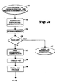
- the scan control unit 22 is provided with an additional algorithm which responds to overload conditions and is described below in connection with FIG. 2a.
- the algorithm is entered from the main loop or the data collection loop at step 100 in response to a system interrupt that is triggered by an overload condition. Then, in steps 102 and 104, the status of the synchronous detector 20, that is to say the size of the measured values acting on it, is determined and an interruption mark is set to the value -1-.
- step 110 which means a return to the data collection loop without interruption. If an overload condition is indicated due to a too high value of the detector 18, then the algorithm is passed from step 106 to step 112, which interrupts the process of data accumulation in the data accumulation loop, to step 114, which contains a count value for overload -OVERLD- with the Amount -0- and to step 116 which causes the algorithm to pause for approximately 1 second.
- step 118 The state of the synchronous detector 20 is then determined again in step 118. If the overload condition has disappeared at this point in time, that is to say at this step, the algorithm is passed from step 120 to step 122, which causes the X and Y mirror drive motors 14, 16 to be reset a few steps. Then, in step 124, there is a return to and start of the scan and data collection, so that new data is accumulated to replace the data containing the overload condition.
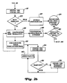
- step 120 the algorithm proceeds to steps 126-140.
- This group of steps acts to count the number of overload situations over a period of time, such as 5-10 seconds. During this period, the overload condition is examined periodically, approximately every 0.1 seconds, and an overload count -OVERLD- increases with each overload condition that occurs. After the number of congestion states has been counted during this period, step 126 leads the algorithm to step 128 which turns off the delay and the loop associated with it for counting the congestion states. If less than a certain number of overload conditions (e.g. less than 30) have occurred, then in step 130 the algorithm is led back to the data collection loop via step 124.
- a certain number of overload conditions e.g. less than 30
- step 144 determines whether information on the accumulated data is displayed on the screen. Otherwise, the algorithm continues with steps 146-150, which cause the sensitivity of the synchronous detector 20 to be automatically adjusted by one step. Following this, there is always a corresponding adjustment of the adjustment factor, which relates to the data collected, so that the X and Y mirror drive motors 14, 16 adjust the mirrors in the scanning device 10. As a result, the scanning process is carried out again for a small, just closed area, so that the data containing the overload condition can be replaced by new data. Finally, in step 152 there is a return to and a start of the data collection loop.
- step 144 If the data is displayed on screen 32, the algorithm proceeds to steps 154-158, which cause a delay of, for example, 2 minutes while the computer is waiting for an operator to input the keyboard 34 does. If no operator input and 2 minutes have passed, the algorithm proceeds to step 164, which ends the waiting time, and then to steps 146-152 described above. If, on the other hand, an input is made by an operator, the algorithm is passed from step 160 to steps 164 and 146-152 described above if the operator has determined that the sensitivity of the synchronous detector 20 is changed. Indicates the operator that a Setting does not take place, then the algorithm leads from step 160 to step 162, in which the delay timer is switched off, and from this back to the data collection circuit via step 152.
Landscapes
- Physics & Mathematics (AREA)
- General Physics & Mathematics (AREA)
- Biochemistry (AREA)
- Life Sciences & Earth Sciences (AREA)
- Chemical & Material Sciences (AREA)
- Analytical Chemistry (AREA)
- Health & Medical Sciences (AREA)
- General Health & Medical Sciences (AREA)
- Immunology (AREA)
- Pathology (AREA)
- Length Measuring Devices With Unspecified Measuring Means (AREA)
- Investigating Strength Of Materials By Application Of Mechanical Stress (AREA)
- Facsimile Scanning Arrangements (AREA)
- Photometry And Measurement Of Optical Pulse Characteristics (AREA)
- Investigating Or Analysing Materials By Optical Means (AREA)
Applications Claiming Priority (2)
| Application Number | Priority Date | Filing Date | Title |
|---|---|---|---|
| US07/204,052 US4828400A (en) | 1988-06-08 | 1988-06-08 | Stress analyzer with automatic overload response |
| US204052 | 1988-06-08 |
Publications (3)
| Publication Number | Publication Date |
|---|---|
| EP0345641A2 true EP0345641A2 (fr) | 1989-12-13 |
| EP0345641A3 EP0345641A3 (fr) | 1991-09-11 |
| EP0345641B1 EP0345641B1 (fr) | 1993-12-22 |
Family
ID=22756421
Family Applications (1)
| Application Number | Title | Priority Date | Filing Date |
|---|---|---|---|
| EP89109919A Expired - Lifetime EP0345641B1 (fr) | 1988-06-08 | 1989-06-01 | Dispositif d'analyse de l'état de charge d'un objet |
Country Status (6)
| Country | Link |
|---|---|
| US (1) | US4828400A (fr) |
| EP (1) | EP0345641B1 (fr) |
| JP (1) | JP2679846B2 (fr) |
| AU (1) | AU3601289A (fr) |
| CA (1) | CA1325731C (fr) |
| DE (1) | DE58906474D1 (fr) |
Cited By (2)
| Publication number | Priority date | Publication date | Assignee | Title |
|---|---|---|---|---|
| WO1991017414A3 (fr) * | 1990-05-09 | 1992-01-09 | Secretary Trade Ind Brit | Evaluation structurale non destructive |
| DE4220544A1 (de) * | 1992-06-24 | 1994-01-05 | Woelfel Horst Prof Dr Ing | Verfahren zum Messen mechanischer Spannungskomponenten an der Oberfläche von dynamisch belasteten Meßobjekten |
Families Citing this family (6)
| Publication number | Priority date | Publication date | Assignee | Title |
|---|---|---|---|---|
| US5201582A (en) * | 1992-05-15 | 1993-04-13 | Stress Photonics, Inc. | Differential temperature stress measurement employing array sensor with local offset |
| US6593574B2 (en) * | 1999-09-16 | 2003-07-15 | Wayne State University | Hand-held sound source gun for infrared imaging of sub-surface defects in materials |
| US6437334B1 (en) | 1999-09-16 | 2002-08-20 | Wayne State University | System and method for detecting cracks in a tooth by ultrasonically exciting and thermally imaging the tooth |
| US6236049B1 (en) | 1999-09-16 | 2001-05-22 | Wayne State University | Infrared imaging of ultrasonically excited subsurface defects in materials |
| EP1214575B1 (fr) | 1999-09-16 | 2004-12-22 | Wayne State University | Dispositif ir sonore miniaturise sans contact d'inspection non destructive a distance |
| GB0128587D0 (en) * | 2001-11-29 | 2002-01-23 | Amersham Pharm Biotech Uk Ltd | Dynamic range |
Family Cites Families (3)
| Publication number | Priority date | Publication date | Assignee | Title |
|---|---|---|---|---|
| GB1601890A (en) * | 1978-05-31 | 1981-11-04 | Sira Institute | Apparatus and method for indicating stress in an object |
| JPS5794627A (en) * | 1980-12-05 | 1982-06-12 | Komatsu Ltd | Stress distribution measuring instrument |
| GB8422873D0 (en) * | 1984-09-11 | 1984-10-17 | Secr Defence | Static stress measurement in object |
-
1988
- 1988-06-08 US US07/204,052 patent/US4828400A/en not_active Expired - Fee Related
-
1989
- 1989-06-01 EP EP89109919A patent/EP0345641B1/fr not_active Expired - Lifetime
- 1989-06-01 DE DE89109919T patent/DE58906474D1/de not_active Expired - Fee Related
- 1989-06-02 AU AU36012/89A patent/AU3601289A/en not_active Abandoned
- 1989-06-07 CA CA000602029A patent/CA1325731C/fr not_active Expired - Fee Related
- 1989-06-08 JP JP1146550A patent/JP2679846B2/ja not_active Expired - Lifetime
Cited By (3)
| Publication number | Priority date | Publication date | Assignee | Title |
|---|---|---|---|---|
| WO1991017414A3 (fr) * | 1990-05-09 | 1992-01-09 | Secretary Trade Ind Brit | Evaluation structurale non destructive |
| DE4220544A1 (de) * | 1992-06-24 | 1994-01-05 | Woelfel Horst Prof Dr Ing | Verfahren zum Messen mechanischer Spannungskomponenten an der Oberfläche von dynamisch belasteten Meßobjekten |
| DE4220544B4 (de) * | 1992-06-24 | 2005-10-20 | Woelfel Horst | Verfahren zum Messen mechanischer Spannungskomponenten an der Oberfläche von dynamisch belasteten Meßobjekten |
Also Published As
| Publication number | Publication date |
|---|---|
| CA1325731C (fr) | 1994-01-04 |
| JP2679846B2 (ja) | 1997-11-19 |
| DE58906474D1 (de) | 1994-02-03 |
| EP0345641A3 (fr) | 1991-09-11 |
| JPH0231123A (ja) | 1990-02-01 |
| US4828400A (en) | 1989-05-09 |
| AU3601289A (en) | 1989-12-14 |
| EP0345641B1 (fr) | 1993-12-22 |
Similar Documents
| Publication | Publication Date | Title |
|---|---|---|
| EP0318768B1 (fr) | Analyseur logique | |
| DE69625000T2 (de) | Schwingungsüberwachungsvorrichtung und Überwachungsverfahren | |
| DE3855445T2 (de) | Verfahren und vorrichtung zum analysieren eines elektro-enzephalogramms | |
| DE3908831C2 (fr) | ||
| DE69221520T2 (de) | Sehr schnelle Autoskaliertopologie für Digitaloszilloskope | |
| DE3327139C2 (de) | Verfahren und Vorrichtung von für die Rekonstruktion einer Wellenform vorgesehenen Daten | |
| DE2244402A1 (de) | Datenverarbeitungsanlage | |
| DE4000443A1 (de) | Messinstrument und verfahren zur behandlung einer abnormalitaet bei einem messinstrument | |
| DE3341766A1 (de) | Verfahren und vorrichtung zum zeitlichen koordinieren von daten | |
| DE2111609A1 (de) | Verfahren und Vorrichtung zur automatischen periodischen Grundlinien- und Normaleichung einer Registriereinrichtung | |
| DE112020003659T5 (de) | Verfahren zur diagnose von anomalien, vorrichtung zur diagnose von anomalienund programm zur diagnose von anomalien | |
| DE102019101184A1 (de) | Störungsdiagnosesystem | |
| EP0345641B1 (fr) | Dispositif d'analyse de l'état de charge d'un objet | |
| DE3430859A1 (de) | Vorrichtung zum bestimmen des spalt- und brutstoffgehaltes des veraschungsrueckstandes in einem behaelter | |
| DE2737490A1 (de) | Verfahren und datenverarbeitungssystem zum verarbeiten von messdaten | |
| DE60110344T2 (de) | Instrument und Verfahren zum Vergleichen von Wellenformen | |
| DE3117073C2 (de) | Einrichtung zur Feststellung des Lidschlages eines Auges | |
| DE69828877T2 (de) | Testsystem für integrierte schaltkreise mit wenigstens einem quasi-autonomen testinstrument | |
| DE2808397A1 (de) | Verfahren und einrichtung zur signalmessung und zur anzeigesteuerung | |
| DE69514932T2 (de) | Einrichtung zur überwachung der spannungen in einer ausrüstung | |
| DE2825792A1 (de) | Elektronische vorrichtung zur kontrolle der funktion eines elektronischen garnreinigers | |
| DE69013459T2 (de) | Messverfahren für die Gleichstrom/Gleichspannungs-Charakteristik von Halbleiterbauteilen. | |
| DE102016004569B4 (de) | Numerische Steuervorrichtung mit Koordinatenwerterfassungsfunktion, die weder ein Skip-Signal noch eine Tastenbetätigung benötigt | |
| DE68918116T2 (de) | Kennzeichenanalyse und steuerung für eine schneidpresse. | |
| DE69000597T2 (de) | Totalisatorgeraet fuer durchflussmessvorrichtungen. |
Legal Events
| Date | Code | Title | Description |
|---|---|---|---|
| PUAI | Public reference made under article 153(3) epc to a published international application that has entered the european phase |
Free format text: ORIGINAL CODE: 0009012 |
|
| AK | Designated contracting states |
Kind code of ref document: A2 Designated state(s): DE FR GB IT SE |
|
| 17P | Request for examination filed |
Effective date: 19900518 |
|
| PUAL | Search report despatched |
Free format text: ORIGINAL CODE: 0009013 |
|
| RHK1 | Main classification (correction) |
Ipc: G01L 1/25 |
|
| AK | Designated contracting states |
Kind code of ref document: A3 Designated state(s): DE FR GB IT SE |
|
| 17Q | First examination report despatched |
Effective date: 19930216 |
|
| ITF | It: translation for a ep patent filed | ||
| GRAA | (expected) grant |
Free format text: ORIGINAL CODE: 0009210 |
|
| AK | Designated contracting states |
Kind code of ref document: B1 Designated state(s): DE FR GB IT SE |
|
| GBT | Gb: translation of ep patent filed (gb section 77(6)(a)/1977) |
Effective date: 19931221 |
|
| REF | Corresponds to: |
Ref document number: 58906474 Country of ref document: DE Date of ref document: 19940203 |
|
| ET | Fr: translation filed | ||
| ITTA | It: last paid annual fee | ||
| PLBE | No opposition filed within time limit |
Free format text: ORIGINAL CODE: 0009261 |
|
| STAA | Information on the status of an ep patent application or granted ep patent |
Free format text: STATUS: NO OPPOSITION FILED WITHIN TIME LIMIT |
|
| 26N | No opposition filed | ||
| EAL | Se: european patent in force in sweden |
Ref document number: 89109919.4 |
|
| PGFP | Annual fee paid to national office [announced via postgrant information from national office to epo] |
Ref country code: DE Payment date: 19970816 Year of fee payment: 9 |
|
| PGFP | Annual fee paid to national office [announced via postgrant information from national office to epo] |
Ref country code: GB Payment date: 19980522 Year of fee payment: 10 |
|
| PGFP | Annual fee paid to national office [announced via postgrant information from national office to epo] |
Ref country code: SE Payment date: 19980611 Year of fee payment: 10 |
|
| PGFP | Annual fee paid to national office [announced via postgrant information from national office to epo] |
Ref country code: FR Payment date: 19980618 Year of fee payment: 10 |
|
| PG25 | Lapsed in a contracting state [announced via postgrant information from national office to epo] |
Ref country code: DE Free format text: LAPSE BECAUSE OF NON-PAYMENT OF DUE FEES Effective date: 19990401 |
|
| PG25 | Lapsed in a contracting state [announced via postgrant information from national office to epo] |
Ref country code: GB Free format text: LAPSE BECAUSE OF NON-PAYMENT OF DUE FEES Effective date: 19990601 |
|
| PG25 | Lapsed in a contracting state [announced via postgrant information from national office to epo] |
Ref country code: SE Free format text: THE PATENT HAS BEEN ANNULLED BY A DECISION OF A NATIONAL AUTHORITY Effective date: 19990629 |
|
| PG25 | Lapsed in a contracting state [announced via postgrant information from national office to epo] |
Ref country code: FR Free format text: THE PATENT HAS BEEN ANNULLED BY A DECISION OF A NATIONAL AUTHORITY Effective date: 19990630 |
|
| GBPC | Gb: european patent ceased through non-payment of renewal fee |
Effective date: 19990601 |
|
| EUG | Se: european patent has lapsed |
Ref document number: 89109919.4 |
|
| REG | Reference to a national code |
Ref country code: FR Ref legal event code: ST |
|
| PG25 | Lapsed in a contracting state [announced via postgrant information from national office to epo] |
Ref country code: IT Free format text: LAPSE BECAUSE OF NON-PAYMENT OF DUE FEES;WARNING: LAPSES OF ITALIAN PATENTS WITH EFFECTIVE DATE BEFORE 2007 MAY HAVE OCCURRED AT ANY TIME BEFORE 2007. THE CORRECT EFFECTIVE DATE MAY BE DIFFERENT FROM THE ONE RECORDED. Effective date: 20050601 |