EP0345706B1 - Emmarchement à marches escamotables pour porte d'accès à un véhicule ferroviaire de transport de voyageurs - Google Patents
Emmarchement à marches escamotables pour porte d'accès à un véhicule ferroviaire de transport de voyageurs Download PDFInfo
- Publication number
- EP0345706B1 EP0345706B1 EP89110157A EP89110157A EP0345706B1 EP 0345706 B1 EP0345706 B1 EP 0345706B1 EP 89110157 A EP89110157 A EP 89110157A EP 89110157 A EP89110157 A EP 89110157A EP 0345706 B1 EP0345706 B1 EP 0345706B1
- Authority
- EP
- European Patent Office
- Prior art keywords
- extended position
- steps
- connecting rod
- spring
- door
- Prior art date
- Legal status (The legal status is an assumption and is not a legal conclusion. Google has not performed a legal analysis and makes no representation as to the accuracy of the status listed.)
- Expired - Lifetime
Links
- 239000012530 fluid Substances 0.000 claims description 2
- 230000000694 effects Effects 0.000 description 6
- 230000007935 neutral effect Effects 0.000 description 5
- RYGMFSIKBFXOCR-UHFFFAOYSA-N Copper Chemical compound [Cu] RYGMFSIKBFXOCR-UHFFFAOYSA-N 0.000 description 1
- 230000015556 catabolic process Effects 0.000 description 1
- 230000005484 gravity Effects 0.000 description 1
Images

Classifications
-
- B—PERFORMING OPERATIONS; TRANSPORTING
- B61—RAILWAYS
- B61D—BODY DETAILS OR KINDS OF RAILWAY VEHICLES
- B61D23/00—Construction of steps for railway vehicles
- B61D23/02—Folding steps for railway vehicles, e.g. hand or mechanically actuated
- B61D23/025—Folding steps for railway vehicles, e.g. hand or mechanically actuated electrically or fluid actuated
Definitions
- the present invention relates to a step with retractable steps for an access door to a rail passenger vehicle, from or to platforms at at least two different levels.
- the plaintiff has manufactured for the wagons of the very high speed line Paris-Lyon a step comprising a fixed lower step and a movable upper step around a horizontal axis between a position returned inside the wagon and a position horizontal exit , under the effect of a jack acting on an articulated polygon connected to an arm making a fixed angle with the surface of the movable step, against the resistance of a spring, until a position is exceeded in neutral beyond which the spring tends to maintain walking either in the extended position or in the retracted position at rest.
- the document EP-A-0 118 400 describes a step with two retractable steps, one of which undergoes a horizontal translation under the effect of a first jack, and the second a 90 ° rotation under the effect of a second cylinder, the movements of the two steps being independent.
- Such steps are however not suitable for allowing passengers to get on and off from or to platforms of different heights above the track, in conditions of sufficient comfort for the vast majority of the public, in particular for young children or the elderly.
- the very high speed train projects for the North of France intended to use the Belgian and English networks and the Channel Tunnel, require the provision of fully retractable steps, allowing the public to get on and off easily cars, with station platforms higher than those of the French network of 210 mm for the Belgian network and 365 mm for the English network, the distance between the edge of the vehicle body and the edge of the platform is also significantly less for the English network than for the French and Belgian networks.
- the present invention therefore aims to provide a step with fully retractable steps allowing easy access of the wagons to the vast majority of the public in stations of different platform levels and with spacings between the profile of the wagons and the edge of the different platform, a step lower not exceeding the lateral spacing of the upper step in the extended position in the case of stopping in stations with the highest platforms, while forming counter step, so as to leave only a small interval between the edge of the upper step and these platforms, while adapting the profile of the wagon to that of such platforms.
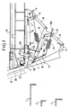
- Figure 1 shows in vertical section the step in the retracted position, door closed, while the train is running.
- Figure 2 shows in vertical section the step in the access position to a platform of the highest level (eg platform of the British network), door open, the upper step alone being accessible to travelers.
- a platform of the highest level eg platform of the British network
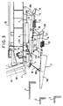
- Figure 3 shows in vertical section the step in the access position to docks of a lower level, the lower step being at a quay of intermediate height (for example quay of the Belgian network) and halfway up between the upper step and an even lower platform (eg platform on the French network).
- a quay of intermediate height for example quay of the Belgian network
- an even lower platform eg platform on the French network
- Figure 1 are represented three platform levels 1 (for example of the British network), 2 (for example of the Belgian network) and 3 (for example of the French network) and the floor 3A of the vehicle in front of the door 3B.
- the access door being closed, the upper step 4 is tucked inside the body and the lower step 13 extends the door downwards by its lower surface.
- a helical spring 12 is fixed on the one hand to an arm 8 linked to the fixed axis 9, on the other hand to the end d 'a connecting rod 12A carried by a fixed axis 12B.
- a second helical spring 19 is fixed on the one hand to an arm 19A linked to the movable axis 23, on the other hand to the end of the connecting rod 18 beyond its pivot point 18A on the middle part of the bottom step 13.
- the rear part of the upper step 4 is connected by a link 20 to the support 21 of a door seal 22, here applied against the bottom of the door.
- FIG. 2 represents the position that the step takes when the train arrives at a station whose platform is on the upper level 1.
- the door 3B is released laterally and takes the position 3C.
- the cylinder 6 pushes the arm 8A and rotates around the axis 9 in a clockwise direction the connecting rod 10, driving up the rear end of the arm 11, which also pivots around the movable axis 23.
- the arm 11 rotates around the movable axis 5 the upper step 4, which, turning around this axis, partially exits the body and comes into the horizontal position, at a level slightly higher than that of the platform 1.
- the connecting rod 14, linked to the movable axis 23, drives the lower end 15 of the lower step 13 towards the inside of the body and upwards, the upper end 17A of which is pushed back by a stop. integral with the upper step 4, so that the lower step 13 forms a counter step below the end of the upper step.
- the latter is held in the extended position by the spring 12, which, driven by the arm 8 secured to the rotary axis 9, has passed the neutral position with respect to this axis and is opposed to any return of step 4 to its original position.
- the spring 19, linked on the one hand to an arm 19A secured to the movable axis 23, on the other hand to the end of the rod 18 fixed to the middle part of the step 13, maintains the latter in its new position.
- the upper step 4 in its rotation drives the link 20, which pivots the support 21 of the door seal 22 backwards and releases the opening of the door.
- FIG. 3 represents the position of the step when the train arrives at a station whose platform is at a lower level 2 or 3.
- the jack 17, pushing the arm 16 linked to the rotary axis 23, makes pivot the connecting rod 14 clockwise around the axis 23, making the bottom end of the step 13 go upwards, the middle part of which remains connected by the connecting rod 18 to the axis 5
- the step 13 therefore assumes a horizontal extended position, at the level of the platform 2 and halfway between the platform 4 and the platform 3. It is held in this position by the spring 19, which, driven by the arm 19A integral axis 23, has exceeded its neutral position vis-à-vis this axis and opposes a return of the step 13 to its initial position.
- the compressed air circuit includes safety devices preventing the door from opening in normal operation if the step does not open.
- the step is provided with a limit switch 24 for the top step, detecting the retracted position of the steps and authorizing the starting of the train only in the closed position of this contact.
- the entire step is determined so that its center of gravity is vertical to axis 5 around which the upper step pivots during its maneuver.
Landscapes
- Engineering & Computer Science (AREA)
- Mechanical Engineering (AREA)
- Vehicle Step Arrangements And Article Storage (AREA)
- Air Bags (AREA)
- Devices For Checking Fares Or Tickets At Control Points (AREA)
- Extensible Doors And Revolving Doors (AREA)
Description
- La présente invention concerne un emmarchement à marches escamotables pour porte d'accès à un véhicule ferroviaire de transport de voyageurs, à partir de ou vers des quais à au moins deux niveaux différents.
- Il s'applique notamment à des véhicules ferroviaires destinés à circuler sur des réseaux, soit nationaux, soit internationaux, dont les hauteurs normalisées de quai au-dessus de la voie sont différentes.
- La demanderesse a fabriqué pour les wagons de la ligne à très grande vitesse Paris-Lyon un emmarchement comprenant une marche inférieure fixe et une marche supérieure mobile autour d'un axe horizontal entre une position rentrée à l'intérieur du wagon et une position sortie horizontale, sous l'effet d'un vérin agissant sur un polygone articulé relié à un bras faisant un angle fixe avec la surface de la marche mobile, à l'encontre de la résistance d'un ressort, jusq'au dépassement d'une position de point mort au-delà de laquelle le ressort tend à maintenir la marche soit en position sortie, soit en position rentrée au repos.
- Le document EP-A-0 118 400 décrit un emmarchement à deux marches escamotables, dont l'une subit une translation horizontale sous l'effet d'un premier vérin, et la seconde une rotation de 90° sous l'effet d'un second vérin, les mouvements des deux marches étant indépendants.
- De tels emmarchements ne conviennent cependant par pour permettre la montée et la descente des voyageurs à partir de, ou vers, des quais de hauteurs différentes au-dessus de la voie, dans des conditions de confort suffisantes pour la grande majorité du public, notamment pour les jeunes enfants ou les personnes âgées. En particulier, les projets de train à très grande vitesse pour le Nord de la France, destinés à emprunter les réseaux belges et anglais et le tunnel sous la Manche, imposent de prévoir des emmarchements entièrement escamotables, permettant au public de monter et de descendre facilement des voitures, avec des quais de gare plus élevés par rapport à ceux du réseau français de 210 mm pour le réseau belge et de 365 mm pour le réseau anglais, l'écartement entre le bord de la caisse du véhicule et le bord du quai étant par ailleurs notablement moindre pour le réseau anglais que pour les réseaux français et belge.
- La présente invention a donc pour but de procurer un emmarchement à marches entièrement escamotables permettant un accès facile des wagons à la grande majorité du public dans des gares de niveaux de quai différents et à écartements entre profil des wagons et bord de quai différents, une marche inférieure ne dépassant pas l'écartement latéral de la marche supérieure en position sortie dans le cas de l'arrêt dans les gares présentant les quais les plus hauts, tout en formant contre marche, de façons à ne laisser subsister qu'un faible intervalle entre le bord de la marche supérieure et ces quais, tout en adaptant le profil du wagon à celui de tels quais. Il a encore pour but d'assurer une stabilité complète des marches dans leurs différentes positions, d'assurer la priorité de l'ouverture et de la fermeture de l'emmarchement par rapport à la porte, d'interdire l'ouverture de la porte, si l'emmarchement ne s'ouvre pas et le démarrage de la rame si l'emmarchement reste en position ouverte, à la suite de pannes du dispositif de commande, tout en permettant alors une commande manuelle.
- L'emmarchement selon l'invention est caractérisé en ce qu'il comprend :
- A) une marche supérieure mobile entre une position rentrée à l'intérieur du véhicule et une position sortie horizontale proche d'un niveau supérieur de quai, sous l'effet d'un vérin agissant sur un polygone articulé comprenant une première bielle pivotant autour d'un axe fixe et entraînant un bras faisant un angle fixe avec la surface de cette marche supérieure, à l'encontre de la résistance d'un premier ressort jusqu'au dépassement d'une position de point mort au-delà de laquelle ce ressort tend à maintenir la marche en position sortie, de façon connue en soi ; et
- B) une marche inférieure mobile
- a) entre une position rentrée dans l'alignement de la caisse du véhicule et une première position sortie formant contremarche pour la marche supérieure en position sortie, sous l'effet du même vérin agissant sur le polygone articulé, dont le bras faisant un angle fixe avec la surface de la marche supérieure est solidaire d'un axe mobile relié par une deuxième bielle à l'extrémité inférieure de la marche inférieure, assurant un rappel vers l'intérieur de la caisse de cette extrémité inférieure, cependant que la partie médiane de cette marche inférieure est rappelée par une deuxième ressort vers un bras solidaire de cet axe mobile, et
- b) entre la première position sortie et une position sortie horizontale correspondant à au moins un niveau inférieur de quai, sous l'effet d'un second vérin agissant sur le polygone articulé, faisant pivoter la bielle reliant l'axe mobile et l'extrémité inférieure de cette marche inférieure, et entraînant vers le haut et vers l'intérieur cette extrémité inférieure, cependant que la partie médiane de cette marche est maintenue à une distance constante d'un axe solidaire de la marche supérieure par une troisième bielle à l'encontre de la résistance du deuxième ressort, jusqu'au dépassement d'une position de point mort au-delà de laquelle il tend à maintenir cette marche inférieure en position horizontale.
- Il répond en outre de préférence à au moins l'une des caractéristiques suivantes :
- La marche supérieure mobile est solidarisée avec une biellette entraînant la rotation d'un support de joint de porte entre une position de fermeture et une position d'ouverture.
- Les vérins sont alimentés par un circuit de fluide ou électrique interdisant l'ouverture de la porte si l'emmarchement ne s'ouvre pas.
- Il es muni d'un organe interdisant la démarrage de la rame si les marches ne sont pas en position rentrée.
- Il est décrit ci-après, à titre d'exemple et en référence aux figures schématiques du dessin annexé, un emmarchement à marches escamotables convenant pour des wagons circulant sur des réseaux à trois hauteurs de quai différentes, telles que celles des quais des réseaux français, anglais et belge, selon l'invention.
- La figure 1 représente en coupe verticale l'emmarchement en position rentrée, porte fermée, pendant la marche de la rame.
- La figure 2 représente en coupe verticale l'emmarchement en position d'accès à un quai du niveau le plus élevé (par exemple quai du réseau britannique), porte ouverte, la marche supérieure seule étant accessible aux voyageurs.
- La figure 3 représente en coupe verticale l'emmarchement en position d'accès à des quais d'un niveau inférieur, la marche inférieure étant au niveau d'un quai de hauteur intermédiaire (par exemple quai du réseau belge) et à mi-hauteur entre la marche supérieure et un quai de hauteur encore inférieure (par exemple quai du réseau français).
- Dans la figure 1 sont représentés trois niveaux de quai 1 (par exemple du réseau britannique), 2 (par exemple du réseau belge) et 3 (par exemple du réseau français) et le plancher 3A du véhicule en face de la porte 3B. La porte d'accès étant fermée, la marche supérieure 4 est rentrée à l'intérieur de la caisse et la marche inférieure 13 prolonge vers le bas la porte par sa surface inférieure. A l'intérieur et sous le plancher en face de la porte sont disposés les vérins pneumatiques de commande 6 et 17, l'axe fixe 9, relié par la bielle 10 au bras 11 solidaire de la marche supérieure et tournant avec celle-ci autour de l'axe 5, l'axe mobile 23 solidaire du bras mobile 11, la bielle 14, reliant l'axe mobile 23 à l'extrémité inférieure 15 de la marche inférieure, et la bielle 18, reliant la partie médiane de la marche inférieure 13 à l'axe de rotation 5 solidaire de la marche supérieure 4. Par ailleurs, un ressort hélicoïdal 12 est fixé d'une part à un bras 8 lié à l'axe fixe 9, d'autre part à l'extrémité d'une bielle 12A portée par un axe fixe 12B. Un second ressort hélicoïdal 19 est fixé d'une part à un bras 19A lié à l'axe mobile 23, d'autre part à l'extrémité de la bielle 18 au-delà de son point de pivotement 18A sur la partie médiane de la marche inférieure 13.
- La partie arrière de la marche supérieure 4 est reliée par une biellette 20 au support 21 d'un joint de porte 22, ici appliqué contre le bas de la porte.
- La figure 2 représente la position que prend l'emmarchement lors de l'arrivée de la rame dans une gare dont le quai est au niveau supérieur 1. La porte 3B se dégage latéralement et prend la position 3C. Le vérin 6 repousse le bras 8A et fait pivoter autour de l'axe 9 dans le sens des aiguilles d'une montre la bielle 10, en entraînant vers le haut l'extrémité arrière du bras 11, qui pivote en outre autour de l'axe mobile 23.
- Le bras 11 entraîne en rotation autour de l'axe mobile 5 la marche supérieure 4, qui, tournant autour de cet axe, sort partiellement de la caisse et vient en position horizontale, à un niveau un peu plus élevé que celui du quai 1. En même temps, la bielle 14, liée à l'axe mobile 23, entraîne vers l'intérieur de la caisse et vers le haut l'extrémité inférieure 15 de la marche inférieure 13, dont l'extrémité supérieure 17A est repoussée par une butée solidaire de la marche supérieure 4, de sorte que la marche inférieure 13 vient former contre-marche au-dessous de l'extrémité de la marche supérieure. Cette dernière est maintenue en position sortie par le ressort 12, qui, entraîné par le bras 8 solidaire du l'axe rotatif 9, a dépassé la position de point mort vis-à-vis de cet axe et s'oppose à tout retour de la marche 4 à sa position initiale. Le ressort 19, lié d'une part à un bras 19A solidaire de l'axe mobile 23, d'autre part à l'extrémité de la bielle 18 fixée à la partie médiane de la marche 13, maintient celle-ci dans sa nouvelle position.
- Par ailleurs, la marche supérieure 4 entraîne dans sa rotation la biellette 20, qui fait pivoter vers l'arrière le support 21 du joint de porte 22 et dégage l'ouverture de la porte.
- La figure 3 représente la position de l'emmarchement lors de l'arrivée de la rame dans une gare dont le quai est à un niveau inférieure 2 ou 3. Le vérin 17, repoussant le bras 16 lié à l'axe rotatif 23, fait pivoter la bielle 14 dans le sens des aiguilles d'une montre autour de l'axe 23, en faisant remonter vers le haut l'extrémité inférieure de la marche 13, dont la partie médiane reste reliée par la bielle 18 à l'axe 5. La marche 13 prend dès lors une position sortie horizontale, à hauteur du quai 2 et à mi-hauteur entre la marche 4 et le quai 3. Elle est maintenue dans cette position par le ressort 19, qui, entraîné par le bras 19A solidaire de l'axe 23, a dépassé sa position de point mort vis-à-vis de cet axe et s'oppose à un retour de la marche 13 à sa position initiale.
- Il est cependant possible en cas de panne du circuit d'air comprimé de manoeuvrer manuellement les marches, qui sont munies de poignées de préhension.
- Le circuit d'air comprimé comporte des organes de sécurité interdisant en marche normale l'ouverture de la porte si l'emmarchement ne s'ouvre pas.
- L'emmarchement est muni d'un contact de fin de course 24 de la marche supérieure, détectant la position rentrée des marches et n'autorisant le démarrage de la rame qu'en position de fermeture de ce contact.
- Afin de réduire la tension du ressort nécessaire pour le maintien des marches en position rentrée ou en position sortie (ainsi que l'effort nécessaire pour une manoeuvre manuelle), on détermine l'ensemble de l'emmarchement de manière que son centre de gravité soit à la verticale de l'axe 5 autour duquel pivote la marche supérieure pendant sa manoeuvre.
Claims (4)
Priority Applications (1)
| Application Number | Priority Date | Filing Date | Title |
|---|---|---|---|
| AT89110157T ATE73066T1 (de) | 1988-06-08 | 1989-06-05 | Einstiegstreppe mit faltstufen fuer eine zugangstuer eines eisenbahnfahrzeuges fuer personenbefoerderung. |
Applications Claiming Priority (2)
| Application Number | Priority Date | Filing Date | Title |
|---|---|---|---|
| FR8807619A FR2632592B1 (fr) | 1988-06-08 | 1988-06-08 | Emmarchement a marches escamotables pour porte d'acces a un vehicule ferroviaire de transport de voyageurs |
| FR8807619 | 1988-06-08 |
Publications (2)
| Publication Number | Publication Date |
|---|---|
| EP0345706A1 EP0345706A1 (fr) | 1989-12-13 |
| EP0345706B1 true EP0345706B1 (fr) | 1992-03-04 |
Family
ID=9367067
Family Applications (1)
| Application Number | Title | Priority Date | Filing Date |
|---|---|---|---|
| EP89110157A Expired - Lifetime EP0345706B1 (fr) | 1988-06-08 | 1989-06-05 | Emmarchement à marches escamotables pour porte d'accès à un véhicule ferroviaire de transport de voyageurs |
Country Status (5)
| Country | Link |
|---|---|
| EP (1) | EP0345706B1 (fr) |
| AT (1) | ATE73066T1 (fr) |
| DE (1) | DE68900909D1 (fr) |
| ES (1) | ES2029919T3 (fr) |
| FR (1) | FR2632592B1 (fr) |
Families Citing this family (12)
| Publication number | Priority date | Publication date | Assignee | Title |
|---|---|---|---|---|
| DE4016620A1 (de) * | 1990-05-23 | 1991-11-28 | Man Ghh Schienenverkehr | Mehrstufiger klapptritt fuer spurgebundene fahrzeuge |
| US5230288A (en) * | 1990-11-29 | 1993-07-27 | Renfe | Entering and exiting step system for vehicles with swingable platform for wheelchair bound passengers |
| US5150659A (en) * | 1990-11-29 | 1992-09-29 | Renfe | Entering and exiting step system for vehicles with two step pivotal support for accommodating platforms of varying heights |
| FR2703317B1 (fr) * | 1993-03-29 | 1995-06-09 | Anf Ind | Emmarchement extensible pour seuil de porte de vehicule ferroviaire. |
| FR2703318B1 (fr) * | 1993-03-29 | 1995-06-23 | Anf Ind | Emmarchement mobile pour porte de vehicule ferroviaire. |
| CA2378914C (fr) | 1999-07-08 | 2007-11-20 | Aai Corporation | Porte coulissante de voiture a voyageurs avec seuil de quai sureleve |
| FR2901223A1 (fr) * | 2006-05-19 | 2007-11-23 | Alstom Transport Sa | Dispositif de marchepied repliable pour vehicule ferroviaire, et vehicule ferroviaire correspondant |
| DE102010022407A1 (de) * | 2010-06-01 | 2011-12-01 | Siemens Aktiengesellschaft | Schienenfahrzeug in Hochflurausführung mit höheneinstellbarer Trittstufe |
| CN103010241B (zh) * | 2013-01-23 | 2015-05-20 | 南车株洲电力机车有限公司 | 一种轨道车辆乘客紧急疏散梯 |
| DE102014207349B4 (de) * | 2014-04-16 | 2022-01-13 | Stadler Pankow GmbH | Verstellvorrichtung zur Höheneinstellung eines an einem Fahrzeug ausfahrbaren Trittelements |
| CN108216266A (zh) * | 2018-03-21 | 2018-06-29 | 南京康尼机电股份有限公司 | 站台门间隙补偿的四连杆翻转式防踏空自动伸缩踏板装置 |
| CN109795418B (zh) * | 2019-01-31 | 2023-09-15 | 安徽三联学院 | 一种基于公交车的可伸缩式台阶 |
Family Cites Families (3)
| Publication number | Priority date | Publication date | Assignee | Title |
|---|---|---|---|---|
| DE3301746C2 (de) * | 1983-01-20 | 1987-01-22 | Messerschmitt-Bölkow-Blohm GmbH, 8012 Ottobrunn | Klapptritt für Schienenfahrzeuge |
| IT8352982V0 (it) * | 1983-02-28 | 1983-02-28 | Fiat Ferroviaria Savigliano | Montatoio a gradini mobili partico larmente per veicoli ferrotramviari |
| DE3708498A1 (de) * | 1987-03-16 | 1988-09-29 | Dowaldwerke | Steuerung fuer eine ausfahrbare eisenbahnwagen-trittstufe |
-
1988
- 1988-06-08 FR FR8807619A patent/FR2632592B1/fr not_active Expired - Fee Related
-
1989
- 1989-06-05 DE DE8989110157T patent/DE68900909D1/de not_active Expired - Fee Related
- 1989-06-05 EP EP89110157A patent/EP0345706B1/fr not_active Expired - Lifetime
- 1989-06-05 AT AT89110157T patent/ATE73066T1/de not_active IP Right Cessation
- 1989-06-05 ES ES198989110157T patent/ES2029919T3/es not_active Expired - Lifetime
Also Published As
| Publication number | Publication date |
|---|---|
| ES2029919T3 (es) | 1992-10-01 |
| FR2632592A1 (fr) | 1989-12-15 |
| FR2632592B1 (fr) | 1990-08-17 |
| EP0345706A1 (fr) | 1989-12-13 |
| ATE73066T1 (de) | 1992-03-15 |
| DE68900909D1 (de) | 1992-04-09 |
Similar Documents
| Publication | Publication Date | Title |
|---|---|---|
| EP0345706B1 (fr) | Emmarchement à marches escamotables pour porte d'accès à un véhicule ferroviaire de transport de voyageurs | |
| EP0026147B1 (fr) | Dispositif d'emperchage automatique d'un véhicule électrique du genre trolleybus | |
| FR2945241A1 (fr) | Vehicule comportant une porte deplacable par un dispositif de leve-vitre | |
| CA2284448C (fr) | Siege tournant a mouvement perfectionne, notamment pour vehicule ferroviaire | |
| FR2669871A1 (fr) | Systeme de marchepieds pour l'entree ou la sortie de vehicules. | |
| EP1369276A1 (fr) | Dispositif formant volet de coffre arrière d'un véhicule automobile | |
| EP2178484B1 (fr) | Dispositif elevateur pour fauteuil roulant | |
| EP0348928B1 (fr) | Emmarchement à marches escamotables pour porte d'accès et de sortie d'un véhicule ferroviaire de transport de voyageurs | |
| EP3206649B1 (fr) | Dispositif de toilettes pour automobilistes handicapés moteurs | |
| EP0884218B1 (fr) | Dispositif de marchepied mobile pour un véhicule automobile | |
| FR2737710A1 (fr) | Installation pour transborder un conteneur d'un wagon ou l'amener sur le wagon | |
| FR2696199A1 (fr) | Chariot à bras télescopique et à pelle excavatrice. | |
| EP0694001B1 (fr) | Dispositif elevateur de fauteuil roulant repliable sur le toit d'un vehicule automobile | |
| FR2491408A1 (fr) | Vehicule automobile pour personnes se deplacant sur un siege mobile | |
| FR2901515A1 (fr) | Vehicule de transport pourvu de moyens d'acces pour personnes a mobilite reduite | |
| EP3235702B1 (fr) | Installation et procede de transport par cable aerien | |
| EP1765624A1 (fr) | Ouvrant de vehicule automobile, et vehicule pourvu d'un tel ouvrant | |
| EP0894486A1 (fr) | Véhicule automobile pour handicapé | |
| EP0707548A1 (fr) | Chariot porte-palette | |
| FR2770813A1 (fr) | Dispositif escamotable de mise au repos d'un hayon elevateur a rails inclines fixes a l'arriere d'un vehicule | |
| FR2588910A1 (fr) | Volet roulant pour fenetre | |
| FR3107653A1 (fr) | Cabine équipée d’un dispositif de verrouillage et de déverrouillage des portes et installation de transport de passagers comprenant au moins une telle cabine | |
| WO2020254938A1 (fr) | Véhicule à moteur pour personne à mobilité réduite, avec montée/descente facilitée | |
| FR2707566A1 (fr) | Agencement de siège de véhicule automobile permettant un mouvement de pivotement autour d'un axe vertical. | |
| FR2504869A1 (fr) | Dispositif de manoeuvre d'un plateau monte mobile, sur un chassis porteur, entre une position horizontale anterieure et une position inclinee posterieure |
Legal Events
| Date | Code | Title | Description |
|---|---|---|---|
| PUAI | Public reference made under article 153(3) epc to a published international application that has entered the european phase |
Free format text: ORIGINAL CODE: 0009012 |
|
| AK | Designated contracting states |
Kind code of ref document: A1 Designated state(s): AT BE CH DE ES FR GB IT LI NL SE |
|
| RAP1 | Party data changed (applicant data changed or rights of an application transferred) |
Owner name: GEC ALSTHOM SA |
|
| 17P | Request for examination filed |
Effective date: 19900611 |
|
| 17Q | First examination report despatched |
Effective date: 19910424 |
|
| GRAA | (expected) grant |
Free format text: ORIGINAL CODE: 0009210 |
|
| AK | Designated contracting states |
Kind code of ref document: B1 Designated state(s): AT BE CH DE ES FR GB IT LI NL SE |
|
| REF | Corresponds to: |
Ref document number: 73066 Country of ref document: AT Date of ref document: 19920315 Kind code of ref document: T |
|
| REF | Corresponds to: |
Ref document number: 68900909 Country of ref document: DE Date of ref document: 19920409 |
|
| GBT | Gb: translation of ep patent filed (gb section 77(6)(a)/1977) | ||
| ITF | It: translation for a ep patent filed | ||
| REG | Reference to a national code |
Ref country code: ES Ref legal event code: FG2A Ref document number: 2029919 Country of ref document: ES Kind code of ref document: T3 |
|
| PLBE | No opposition filed within time limit |
Free format text: ORIGINAL CODE: 0009261 |
|
| STAA | Information on the status of an ep patent application or granted ep patent |
Free format text: STATUS: NO OPPOSITION FILED WITHIN TIME LIMIT |
|
| 26N | No opposition filed | ||
| EAL | Se: european patent in force in sweden |
Ref document number: 89110157.8 |
|
| REG | Reference to a national code |
Ref country code: GB Ref legal event code: IF02 |
|
| PGFP | Annual fee paid to national office [announced via postgrant information from national office to epo] |
Ref country code: SE Payment date: 20070614 Year of fee payment: 19 |
|
| PGFP | Annual fee paid to national office [announced via postgrant information from national office to epo] |
Ref country code: CH Payment date: 20070615 Year of fee payment: 19 Ref country code: NL Payment date: 20070615 Year of fee payment: 19 |
|
| PGFP | Annual fee paid to national office [announced via postgrant information from national office to epo] |
Ref country code: AT Payment date: 20070618 Year of fee payment: 19 |
|
| PGFP | Annual fee paid to national office [announced via postgrant information from national office to epo] |
Ref country code: DE Payment date: 20070622 Year of fee payment: 19 |
|
| PGFP | Annual fee paid to national office [announced via postgrant information from national office to epo] |
Ref country code: ES Payment date: 20070628 Year of fee payment: 19 |
|
| PGFP | Annual fee paid to national office [announced via postgrant information from national office to epo] |
Ref country code: GB Payment date: 20070621 Year of fee payment: 19 |
|
| PGFP | Annual fee paid to national office [announced via postgrant information from national office to epo] |
Ref country code: IT Payment date: 20070626 Year of fee payment: 19 |
|
| PGFP | Annual fee paid to national office [announced via postgrant information from national office to epo] |
Ref country code: BE Payment date: 20070711 Year of fee payment: 19 |
|
| PGFP | Annual fee paid to national office [announced via postgrant information from national office to epo] |
Ref country code: FR Payment date: 20070615 Year of fee payment: 19 |
|
| BERE | Be: lapsed |
Owner name: S.A. *GEC ALSTHOM Effective date: 20080630 |
|
| REG | Reference to a national code |
Ref country code: CH Ref legal event code: PL |
|
| EUG | Se: european patent has lapsed | ||
| GBPC | Gb: european patent ceased through non-payment of renewal fee |
Effective date: 20080605 |
|
| NLV4 | Nl: lapsed or anulled due to non-payment of the annual fee |
Effective date: 20090101 |
|
| PG25 | Lapsed in a contracting state [announced via postgrant information from national office to epo] |
Ref country code: BE Free format text: LAPSE BECAUSE OF NON-PAYMENT OF DUE FEES Effective date: 20080630 |
|
| REG | Reference to a national code |
Ref country code: FR Ref legal event code: ST Effective date: 20090228 |
|
| PG25 | Lapsed in a contracting state [announced via postgrant information from national office to epo] |
Ref country code: DE Free format text: LAPSE BECAUSE OF NON-PAYMENT OF DUE FEES Effective date: 20090101 Ref country code: AT Free format text: LAPSE BECAUSE OF NON-PAYMENT OF DUE FEES Effective date: 20080605 |
|
| PG25 | Lapsed in a contracting state [announced via postgrant information from national office to epo] |
Ref country code: NL Free format text: LAPSE BECAUSE OF NON-PAYMENT OF DUE FEES Effective date: 20090101 |
|
| PG25 | Lapsed in a contracting state [announced via postgrant information from national office to epo] |
Ref country code: LI Free format text: LAPSE BECAUSE OF NON-PAYMENT OF DUE FEES Effective date: 20080630 Ref country code: GB Free format text: LAPSE BECAUSE OF NON-PAYMENT OF DUE FEES Effective date: 20080605 Ref country code: CH Free format text: LAPSE BECAUSE OF NON-PAYMENT OF DUE FEES Effective date: 20080630 |
|
| REG | Reference to a national code |
Ref country code: ES Ref legal event code: FD2A Effective date: 20080606 |
|
| PG25 | Lapsed in a contracting state [announced via postgrant information from national office to epo] |
Ref country code: IT Free format text: LAPSE BECAUSE OF NON-PAYMENT OF DUE FEES Effective date: 20080605 Ref country code: FR Free format text: LAPSE BECAUSE OF NON-PAYMENT OF DUE FEES Effective date: 20080630 |
|
| PG25 | Lapsed in a contracting state [announced via postgrant information from national office to epo] |
Ref country code: ES Free format text: LAPSE BECAUSE OF NON-PAYMENT OF DUE FEES Effective date: 20080606 |
|
| PG25 | Lapsed in a contracting state [announced via postgrant information from national office to epo] |
Ref country code: SE Free format text: LAPSE BECAUSE OF NON-PAYMENT OF DUE FEES Effective date: 20080606 |