EP0345716A2 - Dispositif de mouillage pour presse lithographique - Google Patents
Dispositif de mouillage pour presse lithographique Download PDFInfo
- Publication number
- EP0345716A2 EP0345716A2 EP89110183A EP89110183A EP0345716A2 EP 0345716 A2 EP0345716 A2 EP 0345716A2 EP 89110183 A EP89110183 A EP 89110183A EP 89110183 A EP89110183 A EP 89110183A EP 0345716 A2 EP0345716 A2 EP 0345716A2
- Authority
- EP
- European Patent Office
- Prior art keywords
- roller
- form roller
- plate cylinder
- metering
- plate
- Prior art date
- Legal status (The legal status is an assumption and is not a legal conclusion. Google has not performed a legal analysis and makes no representation as to the accuracy of the status listed.)
- Withdrawn
Links
Images

Classifications
-
- B—PERFORMING OPERATIONS; TRANSPORTING
- B41—PRINTING; LINING MACHINES; TYPEWRITERS; STAMPS
- B41F—PRINTING MACHINES OR PRESSES
- B41F7/00—Rotary lithographic machines
- B41F7/20—Details
- B41F7/24—Damping devices
- B41F7/26—Damping devices using transfer rollers
-
- B—PERFORMING OPERATIONS; TRANSPORTING
- B41—PRINTING; LINING MACHINES; TYPEWRITERS; STAMPS
- B41F—PRINTING MACHINES OR PRESSES
- B41F7/00—Rotary lithographic machines
- B41F7/20—Details
- B41F7/24—Damping devices
- B41F7/32—Ducts, containers, or like supply devices for liquids
Definitions
- the present invention relates to dampening systems for offset lithographic printing presses, and more particularly, to an improvement in the dampening solution feed apparatus which is disclosed in U.S. Patent No. 4,455,938.
- the major components of a typical offset press are the plate cylinder, blanket cylinder, dampening system, and inking system. Secured around the plate cylinder is a planographic printing plate upon which is imposed an image defined by a gradation of oleophilic dots and a hydrophilic background, the intensity of the image being directly proportional to the concentration of such dots.
- the function of the dampening system is to thoroughly moisten only the background of the plate with a substantially aqueous solution.
- Grease-based ink is applied to the plate and adheres only to the oleophilic dots to create an inked image which is transferred to an adjacent blanket cylinder and subsequently to the paper to be printed.
- Prior to the invention disclosed in said US Patent No. 4,455,938, the most common dampening devices used in offset lithographic presses were either of the type disclosed in U.S. Patent No. 4,088,074 issued 9 May 1978, or of the oscillating ductor roller type which has been used in this art for many years.
- the dampening system is a critical element of the press. If the quantity and application of the dampening solution is not precise, the solution and ink will incorrectly coat the respective hydrophilic and oleophilic areas, and the finally printed image will be distorted.
- Conventional ductor roller dampening systems control the amount of solution transferred to the form roller, which contacts the plate cylinder, by adjusting the rate of oscillations of the ductor roller which reciprocates back and forth from a solution reservoir to the train of dampening rollers. The amount of solution which is then actually transferred to the plate is controlled by adjusting the pressure between the form roller and the plate cylinder. Excess solution is nipped between the form roller and the plate cylinder and accumulates on the form roller.
- the present invention is a dampening apparatus for offset lithographic printing presses which incorporates the novel features and arrangements of the dampening apparatus disclosed in US Patent 4,455,938 namely, a form roller supported parallel and tangent to the plate cylinder, a metering roller supported parallel and tangent to the form roller and pressed into contact therewith, a reservoir of dampening solution for the metering roller, preferably lying above and between the form and metering rollers, and a means for regularly supplying solution to the reservoir to maintain the reservoir level.
- the form roller surface moves at a speed which matches the speed of the plate cylinder surface (and thus the speed of the plate) and also matches the surface speed of the metering roller. In the original design this is accomplished by gearing the plate cylinder and form roller together, and preferably but not necessarily also gear driving the metering roller. As described in the US patent, by means of such dampening apparatus an excessive amount of dampening solution is always in contact with the form roller. The amount of solution actually applied is controlled by adjusting the pressure between the form and metering rollers and between the form roller and the plate cylinder. Excess moisture which is retained on the form roller then is continuously returned directly to the reservoir, thus the solution does accumulate and eventually over-dampen the plate.
- the form roller has a surface which is compressible and ink receptive
- the metering roller has a surface which is much more rigid than the form roller and which is also ink receptive.
- the metering roller and the plate cylinder are mechanically driven directly by the press gear drive system, and the form roller is driven from frictional contact with both the plate cylinder and the metering roller.
- the surface velocities of the metering and form rollers and a plate on the plate cylinder are equilibrated.
- the form roller is mounted such that its axis of rotation can be moved parallel to a tangent to the plate cylinder surface, while keeping a parallel relation with the axis of rotation of the plate cylinder and the metering roller. This allows a change in the pressure at the form roller / metering roller nip without affecting the pressure of the form roller against the plate. Also, this adjustment can be made so as to increase the pressure at the form roller / metering roller nip with increase in press speed, for controlling any tendency to transfer excess dampening solution at such higher speeds.
- the primary object of the present invention to provide an improvement in the prior art dampening apparatus for offset printing presses incorporating the aforementioned features; to simplify the gearing system over that of the prior art; to provide an improved gearing system for retrofit into offset lithographic printing presses; to provide a system whereby the pressure of the dampening form roller against the plate can be set to a desired value, and wherein pressure between the form and metering rollers can be increased at higher press speed without changing the form roller to plate pressure.
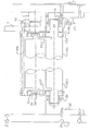
- FIG. 1 shows the existing dampening apparatus, which is disclosed in U.S. Patent No. 4,455,938 and incorporated herein by reference.
- a plate cylinder 10a has a dampening form roller 20a pressed against it, and a metering roller 22a is pressed against the form roller, providing a nip in which the upper part forms a reservoir 26 for dampening solution.
- the form roller 20a is positively gear driven from plate cylinder 10a, and metering roller 22a is frictionally driven from the form roller 20a due to the pressure contact therebetween.
- metering roller 22a can be gear driven from form roller 20a.
- the improvement of the present invention has the plate cylinder 10b and the metering roller 22b mechanically driven by the existing gear drive system of the press. It is necessary only to add gears as appropriate to transfer the drive to the metering roller, since the plate cylinder is already gear driven.
- the form roller 20b is driven from frictional contact with plate cylinder 10b and metering roller 22b, since the form roller is positively pressed against both of them, particularly against the metering roller 22b.
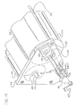
- a pair of support brackets 30 and 32 are fastened (as by bolts) to the side frame members 34 of the press.
- Gear 36 represents a final gear in a train driven from the press drive.
- gear 36 meshes with an idle gear 35 which in turn meshes with a drive gear 11 for driving the plate cylinder 10b.
- Rotary power can be taken from gear 36 to the metering roller 22b for rotating said metering roller at an appropriate speed with respect to said plate cylinder 10b, e.g. at a 1:1 surface speed or with a "built in” slip, if desired.
- Brackets 30 and 32 support roller bearings 38 which in turn receive the extended ends of the shaft 40 of metering roller 22b.
- a snap ring 42 is fitted to one end of shaft 40, outboard of bearing 38 in bracket 30, to locate the dampening unit laterally in brackets 30, 32.
- the structure of the dampener apparatus itself includes side frame members 44 connected by cross rods 46, which are pinned or otherwise fastened at their ends to frame members 44.
- Those frame members include bearings 48 receiving the metering roller shaft 40, and elongated slots 50 which receive blocks 52 that can slide in the slots 50 in a direction generally tangential to form roller 20b.
- Each block 52 includes a roller bearing 54 which receives an end of the form roller shaft 56, supporting the form roller 20b parallel to and in contact with the metering roller 22b.
- the dampener apparatus itself is rotatable about the centerline of metering roller shaft 40. By pivoting the dampening apparatus about said centerline the pressure contact between the form roller 20b and the plate cylinder 10b can be adjusted as will be described below in further details.
- adjustment or control rods 60 Extending from blocks 52, through guide bores 58 in the dampener frame members, are adjustment or control rods 60 which are formed with a number of gear teeth to provide a short rack 62.
- a shaft 64 having small gears 66 thereon, extends between the dampener frame members 44 and is rotatable by a handle 67 pinned to shaft 64, to move control rods 60 in unison, thereby to move the form roller 20b toward and away from the metering roller 22b to adjust the pressure at their nip 68.
- the region above that nip functions (as is known) as the reservoir 26 for dampening solution.
- the pressure of the form roller 20b against the plate on cylinder 10b is achieved by cams 70, fixed to a cross-shaft 72, pressing on a wear plate or follower 74 at the top of each frame member 44. Movement of this mechanism (which is per se known) pre-sets the position of the dampener frame, so as to exert a predetermined pressure of the form roller 20b against a plate on plate cylinder 10b.
- a preferred embodiment of a dampening apparatus comprises a roller system having at least a metering roller 22b and a form roller 20b. A nip between these rollers is closed by seals at the roller ends thereby providing a reservoir 26 for a dampening solution.
- the metering roller 22b is positively driven from the plate cylinder 10b and the form roller 20b is driven by frictional contact with either of the metering roller and the plate cylinder.
- the nip pressure between the form and metering rollers 20b, 22b can be adjusted by shifting the axle of the form roller 20b, and the whole apparatus is rotatable about the axle of the metering roller 22b for adjusting the nip pressure between the form roller 20b and the plate cylinder 10b.
Landscapes
- Engineering & Computer Science (AREA)
- Mechanical Engineering (AREA)
- Rotary Presses (AREA)
- Advancing Webs (AREA)
Applications Claiming Priority (2)
| Application Number | Priority Date | Filing Date | Title |
|---|---|---|---|
| US203351 | 1980-11-03 | ||
| US20335188A | 1988-06-06 | 1988-06-06 |
Publications (2)
| Publication Number | Publication Date |
|---|---|
| EP0345716A2 true EP0345716A2 (fr) | 1989-12-13 |
| EP0345716A3 EP0345716A3 (fr) | 1990-12-19 |
Family
ID=22753619
Family Applications (1)
| Application Number | Title | Priority Date | Filing Date |
|---|---|---|---|
| EP19890110183 Withdrawn EP0345716A3 (fr) | 1988-06-06 | 1989-06-06 | Dispositif de mouillage pour presse lithographique |
Country Status (1)
| Country | Link |
|---|---|
| EP (1) | EP0345716A3 (fr) |
Family Cites Families (5)
| Publication number | Priority date | Publication date | Assignee | Title |
|---|---|---|---|---|
| US3986452A (en) * | 1960-05-02 | 1976-10-19 | Dahlgren Manufacturing Company, Inc. | Liquid applicator for lithographic systems |
| US3769909A (en) * | 1971-03-10 | 1973-11-06 | Rockwell International Corp | Wet nip dampener |
| US3902416A (en) * | 1974-12-04 | 1975-09-02 | Dick Co Ab | Moisture control for lithographic machines |
| US4455938A (en) * | 1979-05-22 | 1984-06-26 | Graph Tech Inc. | Dampening apparatus for lithographic press |
| DE3813829A1 (de) * | 1987-06-25 | 1989-01-05 | Heidelberger Druckmasch Ag | Feuchtwerk fuer eine offsetdruckmaschine |
-
1989
- 1989-06-06 EP EP19890110183 patent/EP0345716A3/fr not_active Withdrawn
Also Published As
| Publication number | Publication date |
|---|---|
| EP0345716A3 (fr) | 1990-12-19 |
Similar Documents
| Publication | Publication Date | Title |
|---|---|---|
| CA1195179A (fr) | Organe d'humidification et d'encrage pour presses offset | |
| CA1311149C (fr) | Alimentateur de films pour presse offset | |
| US4782753A (en) | Printing couple for newspaper and periodical printing | |
| JPH0326127B2 (fr) | ||
| US4208963A (en) | Newspaper printing system | |
| US4397235A (en) | Multi-printing mode rotary printing machine | |
| US4016811A (en) | Grooved roller dampener | |
| GB2082121A (en) | Water supply apparatus for printing press | |
| JP4652517B2 (ja) | 平版印刷機の湿し装置、および、この湿し装置を有する平版印刷機 | |
| US2868118A (en) | Lithographic offset press plate dampening device | |
| US5865116A (en) | Ink receptive dampening system for lithographic printing press | |
| US4981077A (en) | Dampening apparatus for lithographic press | |
| US5341733A (en) | Short inking apparatus for a rotary press | |
| US4986176A (en) | Device for connecting and disconnecting dampening system and inking system in offset printing machine | |
| GB2161753A (en) | An inking unit for a printing press | |
| US5701817A (en) | Apparatus for adjusting the movement of a roller in a printing press | |
| US5046418A (en) | Dampening method and apparatus for automatic ink/water control for lithographic printing press | |
| US5540145A (en) | Ink receptive dampening system for lithographic printing press | |
| EP0345716A2 (fr) | Dispositif de mouillage pour presse lithographique | |
| US5107761A (en) | Friction roller for the inking or moistening unit of printing presses | |
| US4821641A (en) | Dampening and bridging apparatus for a duplicating machine | |
| KR860000864B1 (ko) | 음각판 또는 평판 인쇄기 | |
| KR20010020609A (ko) | 옵셋인쇄기용 인쇄유니트 및 그 작동방법 | |
| CA2047126C (fr) | Rouleau preneur a inversion rapide | |
| CS250216B2 (en) | Equipment for lithography or gravure printing |
Legal Events
| Date | Code | Title | Description |
|---|---|---|---|
| PUAI | Public reference made under article 153(3) epc to a published international application that has entered the european phase |
Free format text: ORIGINAL CODE: 0009012 |
|
| AK | Designated contracting states |
Kind code of ref document: A2 Designated state(s): AT BE CH DE ES FR GB GR IT LI LU NL SE |
|
| PUAL | Search report despatched |
Free format text: ORIGINAL CODE: 0009013 |
|
| AK | Designated contracting states |
Kind code of ref document: A3 Designated state(s): AT BE CH DE ES FR GB GR IT LI LU NL SE |
|
| STAA | Information on the status of an ep patent application or granted ep patent |
Free format text: STATUS: THE APPLICATION IS DEEMED TO BE WITHDRAWN |
|
| 18D | Application deemed to be withdrawn |
Effective date: 19910622 |