EP0345749A2 - Capteur numérique de déviation - Google Patents
Capteur numérique de déviation Download PDFInfo
- Publication number
- EP0345749A2 EP0345749A2 EP89110276A EP89110276A EP0345749A2 EP 0345749 A2 EP0345749 A2 EP 0345749A2 EP 89110276 A EP89110276 A EP 89110276A EP 89110276 A EP89110276 A EP 89110276A EP 0345749 A2 EP0345749 A2 EP 0345749A2
- Authority
- EP
- European Patent Office
- Prior art keywords
- sensor
- deviation
- signal
- counting
- memory
- Prior art date
- Legal status (The legal status is an assumption and is not a legal conclusion. Google has not performed a legal analysis and makes no representation as to the accuracy of the status listed.)
- Withdrawn
Links
Images


Classifications
-
- G—PHYSICS
- G01—MEASURING; TESTING
- G01D—MEASURING NOT SPECIALLY ADAPTED FOR A SPECIFIC VARIABLE; ARRANGEMENTS FOR MEASURING TWO OR MORE VARIABLES NOT COVERED IN A SINGLE OTHER SUBCLASS; TARIFF METERING APPARATUS; MEASURING OR TESTING NOT OTHERWISE PROVIDED FOR
- G01D5/00—Mechanical means for transferring the output of a sensing member; Means for converting the output of a sensing member to another variable where the form or nature of the sensing member does not constrain the means for converting; Transducers not specially adapted for a specific variable
- G01D5/12—Mechanical means for transferring the output of a sensing member; Means for converting the output of a sensing member to another variable where the form or nature of the sensing member does not constrain the means for converting; Transducers not specially adapted for a specific variable using electric or magnetic means
- G01D5/244—Mechanical means for transferring the output of a sensing member; Means for converting the output of a sensing member to another variable where the form or nature of the sensing member does not constrain the means for converting; Transducers not specially adapted for a specific variable using electric or magnetic means influencing characteristics of pulses or pulse trains; generating pulses or pulse trains
- G01D5/245—Mechanical means for transferring the output of a sensing member; Means for converting the output of a sensing member to another variable where the form or nature of the sensing member does not constrain the means for converting; Transducers not specially adapted for a specific variable using electric or magnetic means influencing characteristics of pulses or pulse trains; generating pulses or pulse trains using a variable number of pulses in a train
- G01D5/2451—Incremental encoders
-
- G—PHYSICS
- G01—MEASURING; TESTING
- G01D—MEASURING NOT SPECIALLY ADAPTED FOR A SPECIFIC VARIABLE; ARRANGEMENTS FOR MEASURING TWO OR MORE VARIABLES NOT COVERED IN A SINGLE OTHER SUBCLASS; TARIFF METERING APPARATUS; MEASURING OR TESTING NOT OTHERWISE PROVIDED FOR
- G01D5/00—Mechanical means for transferring the output of a sensing member; Means for converting the output of a sensing member to another variable where the form or nature of the sensing member does not constrain the means for converting; Transducers not specially adapted for a specific variable
- G01D5/12—Mechanical means for transferring the output of a sensing member; Means for converting the output of a sensing member to another variable where the form or nature of the sensing member does not constrain the means for converting; Transducers not specially adapted for a specific variable using electric or magnetic means
- G01D5/244—Mechanical means for transferring the output of a sensing member; Means for converting the output of a sensing member to another variable where the form or nature of the sensing member does not constrain the means for converting; Transducers not specially adapted for a specific variable using electric or magnetic means influencing characteristics of pulses or pulse trains; generating pulses or pulse trains
- G01D5/245—Mechanical means for transferring the output of a sensing member; Means for converting the output of a sensing member to another variable where the form or nature of the sensing member does not constrain the means for converting; Transducers not specially adapted for a specific variable using electric or magnetic means influencing characteristics of pulses or pulse trains; generating pulses or pulse trains using a variable number of pulses in a train
Definitions
- the present invention relates to a deviation sensor device and, particularly, to a digital deviation sensor for digitally measuring an amount of deviation of a movable member.
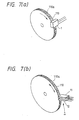
- a deviation sensor such as shown in Fig. 6a, in which a phenomenon is used that, when a slider 102 ganged with a movable member moves on a resistive sheet 100 of resin dispersed with carbon black across which a predetermined voltage is applied, a voltage is produced at a terminal 103 of the slider 102 which is proportional to an amount of deviation of the member.
- a non-contact type deviation sensor one called differential transformer type and shown in Fig. 6b is known in which a magnetic coupling between a primary coil 105 and differentially wound secondary coils 104a and 104b is changed by moving a magnetic member 106 of such as ferrite and a voltage corresponding to an amount of deviation thereof is obtained across opposite ends of the secondary coils 104a and 104b.
- the conventional deviation sensor is constructed as mentioned above and is of an analog type, the sensor is subjected to drift due to temperature and changes of offeset and gain with time. Further, the size thereof is relatively large and circuit construction for processing analog signals is complicated.
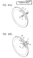
- a Hall or magnetic resistance element 1 for detecting magnetism is used as shown in Fig. 7a or, as shown in Fig. 7b, a pair of such elements 11 and 12 are used.
- a magnetic circular disc 110 has a permanent magnet 110a provided on a periphery thereof.
- the magnet 110a has a plurality of S and N poles arranged alternatively and, when the disc is rotated, an electric pulse output is produced in a magnetism detecting element 1 provided in facing relation to magnetic poles of the magnetic disc 110.
- the magnetism detecting element 1 comprises a first and a second magnetism detecting elements 11 and 12 which produce a pair of pulse trains upon rotation of the disc which are different in phase by 90°.
- a light emissive element 14 is arranged on one side of a slit disc 127 having a number of slits 127a along an outer periphery thereof and a light receiving element 1′ is arranged on the other side such that, when the slit disc 127 rotates, light from the light emissive element 1 reaches the light receiving element 1′ through the respective silts 127a upon which a pulse signal is produced by the light receiving element 1′.
- Fig. 8b two pairs of such photo emissive elements and light receiving elements are arranged to produce two pulse trains as in the Fig. 7b.
- the signal produced is either inputted directly to a controller or indirectly through an amplifier circuit or a waveshaper circuit.
- a controller In such system, it tends to be influenced by noise and, when the inputted signal is supplied to, for example, an interrupt terminal of a microcomputer, signal processing to be performed by the latter becomes excessive, resulting in a delay of a main processing thereof.
- An object of the present invention is to provide a rotation sensor device which is hardly influenced by noise and does not disturb the main processing of such microcomputer, by pretreating pulse signal produced in the side of the sensor.
- Another object of the present invention is to provide a deviation sensor which is of digital type and compact, facilitates a signal conversion with respect to a microcomputer, is hardly influenced by noise, is exchangeable with conventional analog deviation sensor by a conversion of an output into an analog value and has an improved reliability.
- a deviation sensor device comprises a sensor portion for producing an electric pulse signal according to rotation of a shaft, counting means for counting said pulse signals, memory means for storing a count obtained and outputting a stored data serially upon an external clock signal and means responsive to an external trigger signal for producing a timing signal upon which the count is transferred to said memory means to clear the content of said counting means, wherein said rotation sensor device is integrated into substantially a single semiconductor.
- signals in the deviation sensor device is processed within the same semiconductor, it is relatively insensitive to external noise.
- the counter means comprises an up/down counter means for counting said pulse signals according to phase
- the counter data is sent from the memory portion to the side of controller according to an instruction from the controller. Therefore, a signal exchange between a microcomputer as the controller is facilitated and effect of noise becomes negligible. Further, since the deviation amount is digitally measured, effects of drift due to temperature and change of gain with time are reduced.
- a reference numeral 1 depicts a known sensor portion which detects rotation of a rotary member and produces an electric pulse signal corresponding thereto.
- the sensor 1 may be that shown in Fig. 7a or Fig. 8a.
- a counter portion 2 wave-shapes the pulse signal produced in the sensor portion 1 and counts its number.
- a memory portion 3 stores a content of the counter portion 2.
- the memory portion 3 may comprise a shift register circuit having parallel inputs and a serial output.
- a a timing signal forming portion 4 responds to an external trigger pulse signal supplied to a terminal 7 to transfer the data of the counter portion 2 to the memory portion 3, then to clear the counter portion 2 and to perform a switching between an switch input and an output terminals 5 and 6 of the memory portion 3.
- the sensor is connected to an external controller (not shown) by the terminals 5, 6 and 7, the terminal 5 being the serial output terminal for memory data, the terminal 6 being a clock signal input terminal from the controller, the terminal 7 being a trigger signal input terminal.
- the sensor has a power source terminal.
- the rotation sensor device having a construction mentioned above is substantially integraded into a single semiconductor.
- the sensor portion 1 detects rotation of a movable member and produces a pulse signal.
- the pulse signal is sent to the counter portion 2.
- the counter portion 2 comprises an up-counter which counts the number of pulses of the pulse signal.
- a trigger pulse signal is supplied from the controller to the terminal 7
- the counting operation of the counter portion 2 is temporally stopped by a timing signal from the timing signal forming portion 4 and the latter produces a timing signal for transfer of the data of the counter portion 2 to the memory portion 3.
- an operation of the latter is switched to a serial mode and the timing signal forming portion 4 outputs the timing signal for clearing the counter portion 2 and for restarting its counting operation.
- the counter portion 2 counts pulse signals produced by the sensor portion 2 during a time interval of the trigger pulse and transfers a result to the memory portion 3.
- the memory portion 3 outputs the content of the data serially from the terminal 5 upon the clock signal inputted to the clock signal input terminal 6.
- the controller responds to this output signal to calculate a rotational speed of the rotary member.
- the counter portion 2 and the memory portion 3 being of, for example, 16 bits, respectively, it is possible to receive up to about 64,000 pulses as only 16 output pulses when the controller requires them, so that it is possible to reduce a load on the controller. Further, since the output pulse can be obtained reliably with low impedance, it is hardly be influenced by noise.
- Fig. 2 shows a second embodiment of the present invention, in which same reference numerals as those used in Fig. 1 depict same or corresponding portions, respectively, and details thereof are omitted.
- a D/A converter circuit is provided for latching the content of the counter portion 2 according to an instruction of a timing signal forming portion 4 and converting a digital content of the counter into an analog value.
- a terminal 9 is a terminal from which the analog value after D/A converted is outputted.
- the timing signal forming portion 4 has, in addition to the above mentioned function, the same function as that of the timing signal forming portion of the first embodiment.
- the rotation sensor device having the above construction is substantially integrated into a single semiconductor.
- the timing signal outputted from the timing signal forming portion 4 upon a trigger pulse signal supplied through the terminal 7 the data in the counter portion 2 is transferred to the memory portion 3 and to the data latch portion of the D/A converter circuit 8 and outputted at the terminal 9 as an analog value. Further, thetiming signal forming portion 4A clears the counter portion 2 after a transfer of the data of the counter portion 2 to the memory and the D/A converter.
- the second embodiment it is possible, in addition to the effect obtainable by the first embodiment, to record the digital data on a recorder, etc., as analog value.
- the content of the counter portion is D/A converted by the D/A converter circuit
- the content of the memory portion may be converted into an analog value
- a sensor 1 comprises a first sensor portion 11 and a second sensor portion 12 which may be the magnetism detecting elements shown in Fig. 7b or the photo detecting elements shown in Fig. 8b, which are arranged such that output pulse signals S1 and S2 shown in Fig. 4a and having a phase difference of 90° are produced thereby.
- a counter 2 in this embodiment, is an up/down counter responsive to the output signals of the first and second sensor portions 11, 12 for counting pulses from either of the sensor portions according to a direction of deviation of the movable member and the amount thereof.
- the up/downcounter portion 2 has a function to convert the output signal S1 of the first sensor portion 11 into a signal S1′ and the output signal S2 of the second sensor portion 12 into a signal S2′ immediately before counting thereof, on the basis of the output signals S1, S2 of the first and second sensor portions 11, 12, so that only pulses from either of the latters are counted.
- a reference signal generator portion 14 is connected through an OR circuit 14a to the up/down counter portion 2.
- a memory 3 is constructed with, for example, shift registers, which functions to store a content of the up/down counter 2 transferred thereto according to an external instruction and to output it serially according to a switch instruction.
- a timing signal forming portion 4 is supplied externally with a trigger signal, an output side of which is connected to the up/down counter portion 2 and the memory portion 3.
- An output terminal 5 is connected to the memory portion 3 and a clock signal input terminal 6 is connected to the memory portion 3.
- a trigger signal input terminal 7 is connected to the timing signal forming portion 4.
- a reference signal input terminal 20 is connected to the input terminal of the OR circuit 14a, these terminals 5, 6, 7 and 20 being connected to a controller(not shown).
- the deviation sensor constructed as mentioned above is integrated on a single semiconductor.
- the first and the second sensor portiuons 11, 12 produce, upon a deviation of the movable member, pulse signals S1 and S2 whose phases are different from each other by about 90° as shown in Fig. 4a.
- the signal S1 advances in phase by 90° with respect to the signal S2 and, when it is counterclockwise, the phase relation is reversed.
- the up/down counter portion 2 responds to the phases of the output signals S1 and S2 of the first and the second sensor portions 11, 12 to count the numbers of pulses of either S1 or S2. For example, the up/down counter portion 2 processes the signals S1 and S2 to obtain signals S1′ and S2′ as shown in Fig.
- the output of up/down counter portion 2 can indicate the direction of deviation and an amount of deviation.
- the up/down counter portion 13 is cleared by the reference signal from the reference signal generator portion 14 or the refrence signal supplied to the reference signal input terminal 20 from the controller through the OR circuit 14a at a time when the movable member reaches the reference position, so that it is cleared every time the member passes through the reference position.
- the timing signal forming portion 4 responds to the trigger signal supplied by the controller through the trigger signal input terminal 7 to switch an operation of the memory portion 3 to a parallel data input mode, to temporarily stop the counting operation of the up/down counter portion 2 and to transfer the content of the up/down counter portion 2 to the memory portion 3 simultaneously and then to switch the operation of the memory portion 3 so that it can provide a serial output.
- the memory portion 3 is supplied with the clock signal from the clock signal input terminal 6 and provides at the output terminal 5 the stored data in synchronism with the clock signal as a serial pulse train. By receiving this pulse train, the controller can read a deviation.
- Such digital deviation sensor responds to an instruction in the form of trigger signal from the controller to provide the data thereto, in easily readable form.
- Fig. 5 shows a fourth embodiment ofthe present invention, which is similar to the third embodiment shown in Fig. 3 except that a data latch portion 21 connected to the up/down counter portion 2 and a D/A converter 22 are further provided. An analog output of the D/A converter 22 is provided at an analog output terminal 9.
- the data latch portion 21 is in parallel to the memory 3 and its operation is also timed by the timing signal from the timing signal forming portion 4.
- the deviation sensor according to this embodiment is integrated on a single semiconductor.
- the content of the up/down counter portion 2 is delivered to both the memory 3 and the data latch portion 21 in response to the reference signal from the reference signal generator portion 14 or the reference signal from the controller.
- the present invention is also applicable to a linear deviation with the same effect as mentioned previously.
- the pulse signal from the sensor portion is not inputted directly to the microcomputer but preprocessed by the counting means and the memory means such as shift register as memory portion which are integrally formed with the sensor portion, the load on the microcomputer is reduced and the data can be read at any convenient timing. Further, it is possible to obtain stable signal and therefore there is substantially no error due to noise.
- the senor device which produces two pulse signals upon deviation of the movable member, the up/down counter portion for counting the number of the pulse signals, the memory portion for storing the counting and the timing signal forming portion for producing a transfer instruction and a switching instruction being integrated on a single semiconductor, the sensor device is compact, hardly be influenced by noise or aging, provides a simplified signal exchange with a microcomputer.
- the sensor device can provide a exchangeability with a conventional analog deviation sensor.
Landscapes
- Physics & Mathematics (AREA)
- General Physics & Mathematics (AREA)
- Transmission And Conversion Of Sensor Element Output (AREA)
Applications Claiming Priority (6)
| Application Number | Priority Date | Filing Date | Title |
|---|---|---|---|
| JP142245/88 | 1988-06-09 | ||
| JP63142245A JPH01311280A (ja) | 1988-06-09 | 1988-06-09 | 回転センサ装置 |
| JP63145180A JPH01313714A (ja) | 1988-06-13 | 1988-06-13 | デジタル変位センサ |
| JP63145179A JPH01313713A (ja) | 1988-06-13 | 1988-06-13 | デジタル変位センサ |
| JP145180/88 | 1988-06-13 | ||
| JP145179/88 | 1988-06-13 |
Publications (2)
| Publication Number | Publication Date |
|---|---|
| EP0345749A2 true EP0345749A2 (fr) | 1989-12-13 |
| EP0345749A3 EP0345749A3 (fr) | 1991-09-11 |
Family
ID=27318410
Family Applications (1)
| Application Number | Title | Priority Date | Filing Date |
|---|---|---|---|
| EP19890110276 Withdrawn EP0345749A3 (fr) | 1988-06-09 | 1989-06-07 | Capteur numérique de déviation |
Country Status (2)
| Country | Link |
|---|---|
| EP (1) | EP0345749A3 (fr) |
| KR (1) | KR920009695B1 (fr) |
Cited By (1)
| Publication number | Priority date | Publication date | Assignee | Title |
|---|---|---|---|---|
| EP1243828A3 (fr) * | 2001-03-23 | 2003-05-21 | BIFFI ITALIA S.r.L. | Détecteur de position en particulier pour une soupape électrique |
Family Cites Families (3)
| Publication number | Priority date | Publication date | Assignee | Title |
|---|---|---|---|---|
| IT1031424B (it) * | 1974-02-14 | 1979-04-30 | Licentia Gmbh | Dispositivo di conteggio composito di contatore e di cate na magneti ca di conteggio |
| CA1149515A (fr) * | 1979-08-31 | 1983-07-05 | Bendix Corporation (The) | Instrument de mesure |
| AT392536B (de) * | 1984-07-06 | 1991-04-25 | R S F Elektronik Ohg Rechtsfor | Lineares, inkrementales messsystem |
-
1989
- 1989-05-30 KR KR1019890007238A patent/KR920009695B1/ko not_active Expired
- 1989-06-07 EP EP19890110276 patent/EP0345749A3/fr not_active Withdrawn
Cited By (1)
| Publication number | Priority date | Publication date | Assignee | Title |
|---|---|---|---|---|
| EP1243828A3 (fr) * | 2001-03-23 | 2003-05-21 | BIFFI ITALIA S.r.L. | Détecteur de position en particulier pour une soupape électrique |
Also Published As
| Publication number | Publication date |
|---|---|
| EP0345749A3 (fr) | 1991-09-11 |
| KR900000684A (ko) | 1990-01-31 |
| KR920009695B1 (ko) | 1992-10-22 |
Similar Documents
| Publication | Publication Date | Title |
|---|---|---|
| US5412317A (en) | Position detector utilizing absolute and incremental position sensors in combination | |
| US4791366A (en) | Apparatus including a pair of angularly spaced sensors for detecting angle of rotation of a rotary member | |
| CA1335415C (fr) | Appareil de mesure de couple | |
| JPS6352712B2 (fr) | ||
| EP0345749A2 (fr) | Capteur numérique de déviation | |
| RU2079848C1 (ru) | Измерительный преобразователь больших постоянных токов | |
| JPH0125286Y2 (fr) | ||
| JPH0249364Y2 (fr) | ||
| USH939H (en) | Commutator pulse tachometer | |
| JPH01313714A (ja) | デジタル変位センサ | |
| SU1112296A1 (ru) | Датчик тока | |
| SU1739185A1 (ru) | Цифровой датчик линейных перемещений | |
| SU748305A2 (ru) | Цифровой измеритель магнитной индукции | |
| SU994942A1 (ru) | Устройство дл регистрации давлени | |
| RU2060502C1 (ru) | Способ определения угловой и линейной скорости частотными датчиками | |
| SU783689A1 (ru) | Устройство дл регистрации магнитного пол | |
| JPH0136337B2 (fr) | ||
| JPH0740173Y2 (ja) | 角度検出器 | |
| JP3477278B2 (ja) | 磁気式位置センサ | |
| SU838568A1 (ru) | Измеритель скорости вращени | |
| SU746358A2 (ru) | Цифровой измеритель магнитной индукции | |
| JPH01313713A (ja) | デジタル変位センサ | |
| SU842648A1 (ru) | Цифровой измеритель магнитного пол | |
| SU717572A1 (ru) | Устройство дл определени направлени отклон ющего усили | |
| JPS6235356B2 (fr) |
Legal Events
| Date | Code | Title | Description |
|---|---|---|---|
| PUAI | Public reference made under article 153(3) epc to a published international application that has entered the european phase |
Free format text: ORIGINAL CODE: 0009012 |
|
| AK | Designated contracting states |
Kind code of ref document: A2 Designated state(s): DE FR GB |
|
| 17P | Request for examination filed |
Effective date: 19901218 |
|
| PUAL | Search report despatched |
Free format text: ORIGINAL CODE: 0009013 |
|
| AK | Designated contracting states |
Kind code of ref document: A3 Designated state(s): DE FR GB |
|
| STAA | Information on the status of an ep patent application or granted ep patent |
Free format text: STATUS: THE APPLICATION HAS BEEN WITHDRAWN |
|
| 18W | Application withdrawn |
Withdrawal date: 19920113 |