EP0345902A2 - Support system for the form plates or panels of a concrete flooring which has to be cast - Google Patents
Support system for the form plates or panels of a concrete flooring which has to be cast Download PDFInfo
- Publication number
- EP0345902A2 EP0345902A2 EP89201451A EP89201451A EP0345902A2 EP 0345902 A2 EP0345902 A2 EP 0345902A2 EP 89201451 A EP89201451 A EP 89201451A EP 89201451 A EP89201451 A EP 89201451A EP 0345902 A2 EP0345902 A2 EP 0345902A2
- Authority
- EP
- European Patent Office
- Prior art keywords
- drop
- beams
- support system
- plate
- secundary
- Prior art date
- Legal status (The legal status is an assumption and is not a legal conclusion. Google has not performed a legal analysis and makes no representation as to the accuracy of the status listed.)
- Withdrawn
Links
Images


Classifications
-
- E—FIXED CONSTRUCTIONS
- E04—BUILDING
- E04G—SCAFFOLDING; FORMS; SHUTTERING; BUILDING IMPLEMENTS OR AIDS, OR THEIR USE; HANDLING BUILDING MATERIALS ON THE SITE; REPAIRING, BREAKING-UP OR OTHER WORK ON EXISTING BUILDINGS
- E04G11/00—Forms, shutterings, or falsework for making walls, floors, ceilings, or roofs
- E04G11/36—Forms, shutterings, or falsework for making walls, floors, ceilings, or roofs for floors, ceilings, or roofs of plane or curved surfaces end formpanels for floor shutterings
- E04G11/48—Supporting structures for shutterings or frames for floors or roofs
- E04G11/486—Dropheads supporting the concrete after removal of the shuttering; Connecting means on beams specially adapted for dropheads
Definitions
- the invention relates to a support system for the form plates or panels of a concrete flooring which has to be cast, said support system comprising posts for supporting primary beams, which as such may serve for supporting form plates or panels with which use can be made of depoty beams.
- the object of the invention is to execute such a system in such a way that it is possible to remove given parts of the support system after the concrete is partly hardened by which a short building cycle can be realized. In this case, however, at least a number of posts will have to be maintained till the concrete is completely hardened.
- the posts are provided with height-adjusting means near at least one of their ends in such a way that the upper surface of the posts is coming to lie in one plane with either the lower surface of the flooring to be cast or with the lower surface of a form plate, the upper end of a post being shaped by a vertical drop head over which a drop plate is movable in vertical direction, said drop plate being positioned in a mainly horizontal plane and serving to support the primary beams, said drop head comprising means for holding the drop plate at a given place, said means being executed such, that after casting the concrete and after this is at least partly hardened, the drop plate can be moved downward over a given distance for removing given parts of the support system.
- the primary beams as well as the form plates or the form panels and the propely beams, if any, can be removed after the concrete is partly hardened, so that all these parts can be directly used again by which the efficiency of such a support construction can be considerably increased.
- the means for holding the drop plate at a given place in respect of the drop head is shaped by a nut having a helically shaped lower surface resting on a round pin radially extending through the drop head, said nut being provided with an inner radial recess such that the nut can be moved along said pin upwardly in axial direction and after this can be rotated to bring the lower surface onto the pin, after which by further rotating the nut and by this the drop plate will move gradually upwardly till it is engaging an abutment.
- the drop plate By rotating back the nut so the drop plate can be gradually moved downwardly so that it is then possible to remove the primary beams, the form panels and the form plates, if any. After this the nut can be further rotated so that the recess of it can be moved along the pin in the drop head and the nut can move further downwardly. In case of the device according to the invention so the primary beams and further parts, if any, can easily be removed.
- the drop plate will be provided with four lips which are positioned over 90° in respect of each other and are extending obliquely upwardly, the end of a beam being provided with a recess to receive a lip such that a beam is locked in respect of the drop plate and a clamping action will arise between the beam and the drop head.
- the primary beams will be provided with an obliquely upwardly extending rim along at least one of their longitudinal edges to receive the ends of depoty beams.
- These depoty beams may form part of a form panel or not, the upper surface of the form panel then being shaped by a form plate.
- connection bolts need to be applied between the beams by which the mounting and demounting of the support system is considerably facilitated.
- a primary beam may consist of an aluminium profile obtained by extrusion and being provided with end parts to be put onto and coupled with the drop plates.
- the depoty beams are composed of a mainly U-shaped profile and two end parts connected to this profile and being mainly K-shaped, such that the intermediary beams can be put down into two different height positions onto the upwardly extending rims of the longitudinal beams, a nail strip being provided between the free ends of the legs of the U-profile, the legs of the profile comprising an inwardly extending support edge directly below the nail strip for supporting said nail strip.
- the part of the K-shaped end parts which is extending about horizontally will be positioned out of the height of the beam so that the upper surface of the beam may comprise two different positions in respect of the upper surface of the primary beam.
- the profiles can be connected to the form plate in a simple way. In this way form panels can be shaped which may fast be laid down on the primary beams.
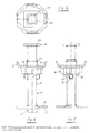
- the support system shown in Fig. 1 comprises the posts 1, being composed of the parts 2, 3 and 4.
- the parts 2 are shaped by screw jacks which in a not further indicated way consist of a spindle over which a nut is rotatable so that the lower ends of the tube parts 3 of the posts can be brought at the same height and can be connected to each other by means of the horizontal connections 5. Further the diagonal rods 6 can be provided to obtain a stable construction.
- the part 4 is shaped by a drop head, the construction of which is further described by means of the Figs. 4 - 6.
- Fig. 1 shows the application of primary beams 7 with various lengths, all at the circumstances bring along with them.
- a support 8 can be mounted on which a guard rail construction 9 can be placed.
- a primary beam is supported at some distance from its end and so is partly cantilevered in which case use can be made of wooden beams or such like instead of a drop head. This, however, will be obvious for an expert.
- Fig. 2 again shows the upper ends of some posts 1 with the screw jacks 2 and the drop heads 4 serving to support primary beams 7 between which dominanty beams 10 are provided.
- Fig. 3 shows a plan view of some primary beams 7 between which excludey beams 10 are provided which may serve to support form plates 11.
- Fig. 3 shows only a part of one form plate 11. The possibility also exists that a form plate 11 is fixedly connected to e.g. two propely beams as will be described afterwards. Then a form panel 26 may be obtained.
- the drop head 4 shown in the Figs. 4, 5 and 6 comprises a base plate 12, being connected to a drop plate 13, indicated by dash-lines, of a screw jack 2.
- the base plate 12 of the drop head 4 is connected to a square tube 14 in which a radially extending round pin 15 is fixed.
- the pin 15 serves to support a nut 16 the lower surface 17 of which is partly helically shaped so that when rotating the nut 16 this will be moved over a given distance in vertical direction. Further the nut 16 is provided with an inner recess 18 so that the nut, after being rotated to its lowest position, may drop down along the pin 15.
- the drop plate 19 On the nut 16 the drop plate 19 is lying comprising the support surface 20 and the lips 21 extending obliquely upward from it.
- the drop plate 19 is provided with a square opening, not further indicated, so that it is only movable in vertical direction along the tube 14 and cannot be rotated in respect of this.
- the tube 14 is further provided with an abutment sleeve 22, said sleeve having a square section as well as the tube 14.
- the upper end of the tube 14 is provided with the front plate 23.
- the upper surface 24 of the front plate 23 may be aligned with the upper surface 25 of the form plates 11, so that afterwards it will directly support the cast concrete flooring. Also the possibility exists that the upper surface 24 of the front plate 23 serves to support the wooden form plate 11. In this case the form plates 11 will be present as long as the posts 1 cannot be removed. See also the Figs. 1-3.
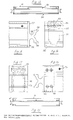
- Figs. 7 and 8 show a part of a primary beam 7 being formed by an aluminium profile 27 obtained by extrusion, the lower part of which is baffled near the end 28.
- an end part 30 is fixed by means of rivets 31 in the upper tubular part 29 of the profile.
- the end part 30 is provided with a recess 32 for receiving a lip 21 of the drop plate 19 in it, as shown in Fig. 4.
- the lip 21 will engage a lower rim 33 forming part of the end part 30.
- the support rims 34 of the aluminium profile 27 are provided with upwardly extending rims 35 for supporting transity beams 10, as these are indicated in Fig. 2 and will be described afterwards by means of the Figs. 12-17.
- the Figs. 9-11 show a primary beam 7 being composed of steel profiles, to wit the mainly U-shaped profile 36 comprising the upper plane 37 and the side planes 38 which at their free ends are bended to form a support rim 39 which in turn is bended to form an upwardly extending rim 40 being provided with the rolled reinforcing rim 41.
- the end part 42 is provided within the beam at its end, said part 42 at its lower end being provided with a recess 43.
- a reinforcing strip 44 is present being connected to the parts 39 and 40 such that a recess 45 is obtained for receiving a lip 21 of the drop plate 19, see Fig. 4.
- the safety plate 46 is provided which prevents that the upper end of the beam 7 is moving towards the tube 14, see Fig. 4, of a drop head 4 when the lower end of the end part 42 engages the abutment sleeve 22.
- a strip 47 is mounted in the end part 42 and serving for connecting a T-profile 48 extending obliquely downwardly as in particular appears from Fig. 9 and which together with a vertical profile 49 is forming a reinforcement of the profile 36.
- Figs. 12-14 show a leadery beam fabricated from an aluminium profile 50 being obtained by extrusion and being mainly U-shaped and comprising the body 51 with the legs 52 extending from it. Between the ends of the legs 52 a nail strip 53 is provided which can be fixed by means of some pop rivets 54. Further the nail strip 53 is supported by the inwardly extending support rims 55 of the profile 50.
- the ends of the profile 50 are provided with end parts 56 being mainly K-shaped and comprising a flange 57, a connecting piece 59 extending mainly horizontally from it and two support lips 59. Because the connecting piece 58 is not positioned in the middle of the height of the profile 50, the propely beam 10 can be laid down onto the support rims 35 or 40, see the Figs. 8 and 11, of a primary beam 7 in two different manners such that the upper surface of the propely beam may be positioned at different levels in respect of the upper surface of the primary beams 7.
- the startery beam 10 according to the Figs. 15-17 mainly corresponds with that according to the Figs. 12-14.
- the beam comprises a U-profile 60 being obtained by bending steel plate.
- a nail strip 53 is present again between the legs of the U-profile and being fixed by means of pop-nails 54 and being supported by support rims formed by inwardly extending portions of the legs of the U-profile.
- the ends of the U-profile 60 are connected to the end parts 61 which are executed in a corresponding way as the end parts 56, but now are provided with a part 62 welded to it and being extended inwardly into the profile 60 and being connected to the profile by means of pop-nails 63.
- end part 56 can be provided with a portion extending inwardly in the profile and that the end part 61 can be connected to the profile 60 directly by means of the flange plate.
Landscapes
- Engineering & Computer Science (AREA)
- Architecture (AREA)
- Mechanical Engineering (AREA)
- Civil Engineering (AREA)
- Structural Engineering (AREA)
- Forms Removed On Construction Sites Or Auxiliary Members Thereof (AREA)
- Building Environments (AREA)
Abstract
Description
- The invention relates to a support system for the form plates or panels of a concrete flooring which has to be cast, said support system comprising posts for supporting primary beams, which as such may serve for supporting form plates or panels with which use can be made of secundary beams.
- Now the object of the invention is to execute such a system in such a way that it is possible to remove given parts of the support system after the concrete is partly hardened by which a short building cycle can be realized. In this case, however, at least a number of posts will have to be maintained till the concrete is completely hardened.
- According to the invention this is obtained because the posts are provided with height-adjusting means near at least one of their ends in such a way that the upper surface of the posts is coming to lie in one plane with either the lower surface of the flooring to be cast or with the lower surface of a form plate, the upper end of a post being shaped by a vertical drop head over which a drop plate is movable in vertical direction, said drop plate being positioned in a mainly horizontal plane and serving to support the primary beams, said drop head comprising means for holding the drop plate at a given place, said means being executed such, that after casting the concrete and after this is at least partly hardened, the drop plate can be moved downward over a given distance for removing given parts of the support system.
- When the upper surface of the posts, so of the support head forming the upper portion of the post, is directly engaging the concrete of the cast flooring, the primary beams as well as the form plates or the form panels and the secundary beams, if any, can be removed after the concrete is partly hardened, so that all these parts can be directly used again by which the efficiency of such a support construction can be considerably increased.
- When the upper surface of the posts is engaging a form plate or a form part shaped in another way, these plates or parts will be held in position till the concrete is completely hardened. This e.g. will be the case when it is desirable that the lower surface of the concrete shows as less irregularities as possible.
- According to an embodiment of the invention the means for holding the drop plate at a given place in respect of the drop head is shaped by a nut having a helically shaped lower surface resting on a round pin radially extending through the drop head, said nut being provided with an inner radial recess such that the nut can be moved along said pin upwardly in axial direction and after this can be rotated to bring the lower surface onto the pin, after which by further rotating the nut and by this the drop plate will move gradually upwardly till it is engaging an abutment.
- By rotating back the nut so the drop plate can be gradually moved downwardly so that it is then possible to remove the primary beams, the form panels and the form plates, if any. After this the nut can be further rotated so that the recess of it can be moved along the pin in the drop head and the nut can move further downwardly. In case of the device according to the invention so the primary beams and further parts, if any, can easily be removed.
- In particular the drop plate will be provided with four lips which are positioned over 90° in respect of each other and are extending obliquely upwardly, the end of a beam being provided with a recess to receive a lip such that a beam is locked in respect of the drop plate and a clamping action will arise between the beam and the drop head.
- In this way it is possible to execute a part of a beam in a cantilevered way when this is desirable for one reason or another.
- In particular the primary beams will be provided with an obliquely upwardly extending rim along at least one of their longitudinal edges to receive the ends of secundary beams. These secundary beams may form part of a form panel or not, the upper surface of the form panel then being shaped by a form plate.
- So then no connection bolts need to be applied between the beams by which the mounting and demounting of the support system is considerably facilitated.
- According to a possible embodiment of the invention a primary beam may consist of an aluminium profile obtained by extrusion and being provided with end parts to be put onto and coupled with the drop plates.
- The possibility consists, however, also to execute the primary beams from steel profiles so that a lattice girder exists.
- The selection of executing from aluminium or steel primary will be made based on the length of the beams and the desired bearing capacity of them while further obviously the cost price, the life and the own weight will play a role.
- According to a preferred embodiment of the invention the secundary beams are composed of a mainly U-shaped profile and two end parts connected to this profile and being mainly K-shaped, such that the secundary beams can be put down into two different height positions onto the upwardly extending rims of the longitudinal beams, a nail strip being provided between the free ends of the legs of the U-profile, the legs of the profile comprising an inwardly extending support edge directly below the nail strip for supporting said nail strip.
- Obviously the part of the K-shaped end parts which is extending about horizontally, will be positioned out of the height of the beam so that the upper surface of the beam may comprise two different positions in respect of the upper surface of the primary beam.
- By comprising a nail strip in the profiles, the profiles can be connected to the form plate in a simple way. In this way form panels can be shaped which may fast be laid down on the primary beams.
- Now the invention is described by means of embodiments, shown in the drawing, in which:
- Fig. 1 schematically shows a view of a support system according to the invention;
- Fig. 2 schematically shows a side view of the upper part of the system of Fig. 1;
- Fig. 3 schematically shows a plan view of a part of the system of Fig. 1;
- Fig. 4 shows a view of a drop head;
- Fig. 5 and 6 show a side view and a plan view respectively of the drop head of Fig. 4;
- Fig. 7 shows a side view of a part of a primary beam from aluminium;
- Fig. 8 shows an end view of the beam of Fig. 7;
- Fig. 9 shows a side view of a primary beam composed of steel profiles;
- Fig. 10 shows a part, on an enlarged scale, of the end of the beam of Fig. 9;
- Fig. 11 shows an end view of the beam of Fig. 10;
- Fig. 12 shows a side view of a secundary beam from aluminium;
- Fig. 13 shows an end, at an enlarged scale, of the beam of Fig. 12;
- Fig. 14 shows an end view of the beam of Fig. 13;
- Fig. 15 shows a side view of a secundary beam from a steel profile;
- Fig. 16 shows an end, at an enlarged scale, of the beam of Fig. 15; and
- Fig. 17 shows an end view of the beam of Fig. 16.
- The support system shown in Fig. 1 comprises the posts 1, being composed of the
parts parts 2 are shaped by screw jacks which in a not further indicated way consist of a spindle over which a nut is rotatable so that the lower ends of the tube parts 3 of the posts can be brought at the same height and can be connected to each other by means of thehorizontal connections 5. Further thediagonal rods 6 can be provided to obtain a stable construction. Thepart 4 is shaped by a drop head, the construction of which is further described by means of the Figs. 4 - 6. - Fig. 1 shows the application of
primary beams 7 with various lengths, all at the circumstances bring along with them. In Fig. 1 further is shown that on the outer posts asupport 8 can be mounted on which a guard rail construction 9 can be placed. It is also possible that a primary beam is supported at some distance from its end and so is partly cantilevered in which case use can be made of wooden beams or such like instead of a drop head. This, however, will be obvious for an expert. - Fig. 2 again shows the upper ends of some posts 1 with the
screw jacks 2 and thedrop heads 4 serving to supportprimary beams 7 between whichsecundary beams 10 are provided. - Fig. 3 shows a plan view of some
primary beams 7 between whichsecundary beams 10 are provided which may serve to supportform plates 11. Fig. 3 shows only a part of oneform plate 11. The possibility also exists that aform plate 11 is fixedly connected to e.g. two secundary beams as will be described afterwards. Then aform panel 26 may be obtained. - The
drop head 4 shown in the Figs. 4, 5 and 6 comprises abase plate 12, being connected to adrop plate 13, indicated by dash-lines, of ascrew jack 2. Thebase plate 12 of thedrop head 4 is connected to asquare tube 14 in which a radially extending roundpin 15 is fixed. Thepin 15 serves to support anut 16 thelower surface 17 of which is partly helically shaped so that when rotating thenut 16 this will be moved over a given distance in vertical direction. Further thenut 16 is provided with an inner recess 18 so that the nut, after being rotated to its lowest position, may drop down along thepin 15. - On the
nut 16 thedrop plate 19 is lying comprising thesupport surface 20 and thelips 21 extending obliquely upward from it. Thedrop plate 19 is provided with a square opening, not further indicated, so that it is only movable in vertical direction along thetube 14 and cannot be rotated in respect of this. - The
tube 14 is further provided with anabutment sleeve 22, said sleeve having a square section as well as thetube 14. When thenut 16 is rotated thedrop plate 19 can be moved upwardly till it is clamped against theabutment sleeve 22. - The upper end of the
tube 14 is provided with thefront plate 23. Theupper surface 24 of thefront plate 23 may be aligned with theupper surface 25 of theform plates 11, so that afterwards it will directly support the cast concrete flooring. Also the possibility exists that theupper surface 24 of thefront plate 23 serves to support thewooden form plate 11. In this case theform plates 11 will be present as long as the posts 1 cannot be removed. See also the Figs. 1-3. - The Figs. 7 and 8 show a part of a
primary beam 7 being formed by analuminium profile 27 obtained by extrusion, the lower part of which is baffled near theend 28. In the uppertubular part 29 of the profile anend part 30 is fixed by means ofrivets 31. Theend part 30 is provided with arecess 32 for receiving alip 21 of thedrop plate 19 in it, as shown in Fig. 4. Thelip 21 will engage alower rim 33 forming part of theend part 30. - The support rims 34 of the
aluminium profile 27 are provided with upwardly extendingrims 35 for supportingsecundary beams 10, as these are indicated in Fig. 2 and will be described afterwards by means of the Figs. 12-17. The Figs. 9-11 show aprimary beam 7 being composed of steel profiles, to wit the mainlyU-shaped profile 36 comprising theupper plane 37 and the side planes 38 which at their free ends are bended to form asupport rim 39 which in turn is bended to form an upwardly extendingrim 40 being provided with the rolled reinforcingrim 41. Theend part 42 is provided within the beam at its end, saidpart 42 at its lower end being provided with arecess 43. Near this recess a reinforcingstrip 44 is present being connected to theparts recess 45 is obtained for receiving alip 21 of thedrop plate 19, see Fig. 4. Near the upper end of theend part 42 thesafety plate 46 is provided which prevents that the upper end of thebeam 7 is moving towards thetube 14, see Fig. 4, of adrop head 4 when the lower end of theend part 42 engages theabutment sleeve 22. - Further a
strip 47 is mounted in theend part 42 and serving for connecting a T-profile 48 extending obliquely downwardly as in particular appears from Fig. 9 and which together with avertical profile 49 is forming a reinforcement of theprofile 36. - As appears from Fig. 1 more
vertical profiles 49 can be provided in case of longerprimary beams 7 which then can be mutually connected by horizontal profiles. - The Figs. 12-14 show a secundary beam fabricated from an
aluminium profile 50 being obtained by extrusion and being mainly U-shaped and comprising thebody 51 with the legs 52 extending from it. Between the ends of the legs 52 anail strip 53 is provided which can be fixed by means of somepop rivets 54. Further thenail strip 53 is supported by the inwardly extendingsupport rims 55 of theprofile 50. - By means of the nail strip 53 a connection can be obtained between a
form plate 11 and asecundary beam 10, so thatform panels 26 may be obtained which may be directly mounted on theprimary beams 7. - The ends of the
profile 50 are provided withend parts 56 being mainly K-shaped and comprising aflange 57, a connectingpiece 59 extending mainly horizontally from it and twosupport lips 59. Because the connectingpiece 58 is not positioned in the middle of the height of theprofile 50, thesecundary beam 10 can be laid down onto the support rims 35 or 40, see the Figs. 8 and 11, of aprimary beam 7 in two different manners such that the upper surface of the secundary beam may be positioned at different levels in respect of the upper surface of theprimary beams 7. - The
secundary beam 10 according to the Figs. 15-17 mainly corresponds with that according to the Figs. 12-14. In this case, however, the beam comprises a U-profile 60 being obtained by bending steel plate. Anail strip 53 is present again between the legs of the U-profile and being fixed by means of pop-nails 54 and being supported by support rims formed by inwardly extending portions of the legs of the U-profile. The ends of the U-profile 60 are connected to theend parts 61 which are executed in a corresponding way as theend parts 56, but now are provided with apart 62 welded to it and being extended inwardly into theprofile 60 and being connected to the profile by means of pop-nails 63. - It will be obvious that also the
end part 56 can be provided with a portion extending inwardly in the profile and that theend part 61 can be connected to theprofile 60 directly by means of the flange plate. - Further it can be remarked that during the mounting of the secundary beams 10 on the primary beams 7 a clamping action can be executed on the last mentioned beams so that they will not have the tendency to twist also not when they are supporting secundary beams only at one side.
- It will be obvious that only some possible embodiments are shown in the drawing and described above and that many modifications can be provided without leaving the inventive concept.
Claims (8)
characterized in
that the posts (1) are provided with height-adjusting means (2) near at least one of their ends in such a way that the upper surface (24) of the posts (1) is coming to lie in one plane with either the lower surface of the flooring to be cast or with the lower surface of a form plate (11) or such like, the upper end of a post (1) being shaped by a vertical drop head (4) over which a drop plate (19) is movable in vertical direction, said drop plate being positioned in a mainly horizontal plane and serving to support the primary beams (7), said drop head (4) comprising means (15-18) for holding the drop plate (19) at a given place, said means (15-18) being executed such, that after casting the concrete and after this is at least partly hardened, the drop plate (19) can be moved downward over a given distance for removing given parts of the support system.
characterized in
that the means for holding the drop plate (19) at a given place in respect of the drop head (4) is shaped by a nut (16) having a helically shaped lower surface (17) resting on a pin (15) radially extending through the drop head (4), said nut (16) being provided with an inner radial recess (18) such that the nut (16) can be moved along said pin (15) upwardly in axial direction and after this can be rotated to bring the lower surface (17) onto the pin (15), after which by further rotating the nut (16) and by this the drop plate (19) will move gradually upwardly till it is engaging an abutment sleeve (22).
characterized in
that the drop plate (19) is provided with four lips (21) which are positioned over 90° in respect of each other and are extending obliquely upwardly, the end of a primary beam (7) being provided with recesses (32,45) to receive the lips (21) such that a primary beam (7) is simultaneously locked in respect of the drop plate (19).
characterized in
that the primary beams (7) are provided with an obliquely upwardly extending rim (35,40) along at least one of their longitudinal edges (34,39) to receive the ends of secundary beams (10).
characterized in
that a primary beam (7) consists of an aluminium profile (27) obtained by extrusion and being provided with end parts (30) to be put onto and coupled with the drop plates (19).
characterized in
that a primary beam consists of steel profiles (36, 48,49) so that a lattice girder exists, said girder being provided with end parts (42) to be put onto and coupled with the drop plates (19).
characterized in
that the secundary beams (10) are composed of a mainly U-shaped profile (50,60) and two end parts (56,61) connected to this profile and being mainly K-shaped, such that the secundary beams (7) can be put down into two different height positions onto the upwardly extending rims (35,40) of longitudinal beams (7), a nail strip (53) being provided between the free ends of the legs (52) of the U-profile, the legs of the profile comprising an inwardly extending support edge (55) directly below the nail strip (53) for supporting said nail strip (53).
characterized in
that said form panel (26) consists of a form plate (11) being connected to at least two secundary beams (10).
Applications Claiming Priority (2)
| Application Number | Priority Date | Filing Date | Title |
|---|---|---|---|
| NL8801475 | 1988-06-08 | ||
| NL8801475A NL8801475A (en) | 1988-06-08 | 1988-06-08 | SUPPORT CONSTRUCTION FOR FORMWORK SHEETS OR PANELS OF A CONCRETE FLOOR. |
Publications (2)
| Publication Number | Publication Date |
|---|---|
| EP0345902A2 true EP0345902A2 (en) | 1989-12-13 |
| EP0345902A3 EP0345902A3 (en) | 1990-01-31 |
Family
ID=19852433
Family Applications (1)
| Application Number | Title | Priority Date | Filing Date |
|---|---|---|---|
| EP89201451A Withdrawn EP0345902A3 (en) | 1988-06-08 | 1989-06-06 | Support system for the form plates or panels of a concrete flooring which has to be cast |
Country Status (2)
| Country | Link |
|---|---|
| EP (1) | EP0345902A3 (en) |
| NL (1) | NL8801475A (en) |
Cited By (14)
| Publication number | Priority date | Publication date | Assignee | Title |
|---|---|---|---|---|
| FR2689547A1 (en) * | 1992-04-04 | 1993-10-08 | Dingler Gerhard | Central beam profiled. |
| FR2689543A1 (en) * | 1992-04-03 | 1993-10-08 | Coffrages Ricard | Supporting framework, e.g. for floor slab shuttering - uses secondary beams with coupling elements on its ends to engage with main beams |
| GR950100447A (en) * | 1995-12-15 | 1997-08-29 | A bolt system for the support of concrete moulds featuring rapid removal of the moulding. | |
| KR100763003B1 (en) | 2006-04-28 | 2007-10-02 | 심상경 | Formwork Support for Slabs |
| KR100792735B1 (en) | 2006-05-12 | 2008-01-08 | 안종식 | Formwork supporting structure |
| KR100817883B1 (en) | 2006-11-02 | 2008-04-01 | 안종식 | Slab formwork installation structure |
| KR100859160B1 (en) | 2007-03-29 | 2008-09-19 | 구자환 | Slab formwork system |
| WO2011037304A1 (en) * | 2009-09-22 | 2011-03-31 | 금강공업(주) | Slab panel, construction system thereof, and method for assembling and disassembling slab panel |
| US20190277044A1 (en) * | 2018-03-12 | 2019-09-12 | Faresin Formwork S.p.A. | Support device, of the drop head type, for supporting beams of formworks for floor slabs, apparatus comprising such device and supporting beam to be associated with the device |
| WO2021111008A1 (en) * | 2019-12-07 | 2021-06-10 | Peri Gmbh | Filler beam assembly |
| US11047142B1 (en) * | 2020-07-31 | 2021-06-29 | Bond Formwork Systems, LLC | Main beam structure and profile for formwork grid systems |
| FR3122891A1 (en) * | 2021-05-17 | 2022-11-18 | Alphi | PRIMARY BEAM WITH FITTED ATTACHMENTS |
| US11603673B2 (en) * | 2017-06-19 | 2023-03-14 | Peri Se | Support head having a lowerable support height for a formwork support |
| US11692362B2 (en) * | 2020-02-10 | 2023-07-04 | Peri Se | Equalizing beam for receiving formwork elements |
Family Cites Families (4)
| Publication number | Priority date | Publication date | Assignee | Title |
|---|---|---|---|---|
| NO801984L (en) * | 1979-07-14 | 1981-01-15 | Sgb Group Ltd | DEVELOPING SYSTEM DEVICE. |
| DE3004245C2 (en) * | 1980-02-06 | 1987-01-02 | Peri-Werk Artur Schwörer GmbH & Co KG, 7912 Weißenhorn | Slab formwork with drop heads |
| DE3147081C2 (en) * | 1981-05-30 | 1987-01-15 | Udo 4836 Herzebrock Rose | Scaffolding for concrete formwork |
| NL192993C (en) * | 1985-12-02 | 1998-07-03 | Petrus Johannes Lambertus De L | Formwork system. |
-
1988
- 1988-06-08 NL NL8801475A patent/NL8801475A/en not_active Application Discontinuation
-
1989
- 1989-06-06 EP EP89201451A patent/EP0345902A3/en not_active Withdrawn
Cited By (24)
| Publication number | Priority date | Publication date | Assignee | Title |
|---|---|---|---|---|
| FR2689543A1 (en) * | 1992-04-03 | 1993-10-08 | Coffrages Ricard | Supporting framework, e.g. for floor slab shuttering - uses secondary beams with coupling elements on its ends to engage with main beams |
| FR2689547A1 (en) * | 1992-04-04 | 1993-10-08 | Dingler Gerhard | Central beam profiled. |
| BE1007922A3 (en) * | 1992-04-04 | 1995-11-21 | Dingler Gerhard | Profiled beam central. |
| ES2089935A2 (en) * | 1992-04-04 | 1996-10-01 | Gerhard Dingler | Shuttering system |
| AT410236B (en) * | 1992-04-04 | 2003-03-25 | Dingler Gerhard | PROFILE MAIN CARRIER |
| GR950100447A (en) * | 1995-12-15 | 1997-08-29 | A bolt system for the support of concrete moulds featuring rapid removal of the moulding. | |
| KR100763003B1 (en) | 2006-04-28 | 2007-10-02 | 심상경 | Formwork Support for Slabs |
| KR100792735B1 (en) | 2006-05-12 | 2008-01-08 | 안종식 | Formwork supporting structure |
| KR100817883B1 (en) | 2006-11-02 | 2008-04-01 | 안종식 | Slab formwork installation structure |
| KR100859160B1 (en) | 2007-03-29 | 2008-09-19 | 구자환 | Slab formwork system |
| WO2011037304A1 (en) * | 2009-09-22 | 2011-03-31 | 금강공업(주) | Slab panel, construction system thereof, and method for assembling and disassembling slab panel |
| US11603673B2 (en) * | 2017-06-19 | 2023-03-14 | Peri Se | Support head having a lowerable support height for a formwork support |
| US12188243B2 (en) * | 2017-06-19 | 2025-01-07 | Peri Se | Support head having a lowerable support height for a formwork support |
| US10883283B2 (en) * | 2018-03-12 | 2021-01-05 | Faresin Formwork S.p.A. | Support device, of the drop head type, for supporting beams of formworks for floor slabs, apparatus comprising such device and supporting beam to be associated with the device |
| US20190277044A1 (en) * | 2018-03-12 | 2019-09-12 | Faresin Formwork S.p.A. | Support device, of the drop head type, for supporting beams of formworks for floor slabs, apparatus comprising such device and supporting beam to be associated with the device |
| WO2021111008A1 (en) * | 2019-12-07 | 2021-06-10 | Peri Gmbh | Filler beam assembly |
| CN114829718A (en) * | 2019-12-07 | 2022-07-29 | Peri欧洲公司 | Filler beam assembly |
| US11773607B2 (en) | 2019-12-07 | 2023-10-03 | Peri Se | Filler beam assembly |
| CN114829718B (en) * | 2019-12-07 | 2024-08-30 | Peri欧洲公司 | Filling beam assembly |
| US12428861B2 (en) | 2019-12-07 | 2025-09-30 | Peri Se | Filler beam assembly |
| US11692362B2 (en) * | 2020-02-10 | 2023-07-04 | Peri Se | Equalizing beam for receiving formwork elements |
| US11047142B1 (en) * | 2020-07-31 | 2021-06-29 | Bond Formwork Systems, LLC | Main beam structure and profile for formwork grid systems |
| US11473321B2 (en) * | 2020-07-31 | 2022-10-18 | Bond Formwork Systems, LLC | Main beam structure and profile for formwork grid systems |
| FR3122891A1 (en) * | 2021-05-17 | 2022-11-18 | Alphi | PRIMARY BEAM WITH FITTED ATTACHMENTS |
Also Published As
| Publication number | Publication date |
|---|---|
| NL8801475A (en) | 1990-01-02 |
| EP0345902A3 (en) | 1990-01-31 |
Similar Documents
| Publication | Publication Date | Title |
|---|---|---|
| EP0345902A2 (en) | Support system for the form plates or panels of a concrete flooring which has to be cast | |
| US4697397A (en) | Trussed girder, roof framing using the trussed girder and method of constructing the roof framing of a building using the trussed girder | |
| US4253549A (en) | Method and a system for the erection of high buildings | |
| US3466824A (en) | Modular space deck | |
| EP0480683A1 (en) | Erection workbench and construction process | |
| US20150204091A1 (en) | Method and apparatus for raising a structure | |
| US6368022B1 (en) | Lifting system for massive constructions | |
| CA2498870C (en) | Suspended cable scaffold assembly | |
| CN111101444A (en) | Bridge cantilever support assembly with connecting elements | |
| US20220412022A1 (en) | Monorail system and related scaffold structures, systems and methods of use | |
| US4577727A (en) | Scaffold for the construction of round buildings of concrete or the like | |
| EP2080853A1 (en) | Stabilizing receiving member for temporary structures | |
| US4249870A (en) | Climbing framework for erecting concrete forms in the manufacture of straight or curved reinforced concrete walls | |
| JP2927320B2 (en) | How to assemble a large hanging boiler | |
| CN221143605U (en) | Large-span steel truss operation assembly combined jig frame | |
| CN107035037B (en) | Tower top curtain wall frame and mounting method thereof | |
| CN214658788U (en) | Retractable's concrete floor formwork structure | |
| GB1568355A (en) | Building platform structures | |
| CN118911022B (en) | Movable bridge temporary support channel dismantling device and use method | |
| JPH0913505A (en) | How to adjust the height of the cantilever roof | |
| JP3100574B2 (en) | Suspended scaffold and its erection method | |
| CN217480770U (en) | Portable operation platform of construction is chosen outward to floor | |
| CN224161395U (en) | Telescopic Adjustable Base Frame for Building Structure | |
| CN215631510U (en) | Steel construction canopy construction platform | |
| FI96049C (en) | Auditorium with load-bearing structure |
Legal Events
| Date | Code | Title | Description |
|---|---|---|---|
| PUAI | Public reference made under article 153(3) epc to a published international application that has entered the european phase |
Free format text: ORIGINAL CODE: 0009012 |
|
| AK | Designated contracting states |
Kind code of ref document: A2 Designated state(s): DE FR GB NL |
|
| PUAL | Search report despatched |
Free format text: ORIGINAL CODE: 0009013 |
|
| AK | Designated contracting states |
Kind code of ref document: A3 Designated state(s): DE FR GB NL |
|
| 17P | Request for examination filed |
Effective date: 19900611 |
|
| 17Q | First examination report despatched |
Effective date: 19910404 |
|
| STAA | Information on the status of an ep patent application or granted ep patent |
Free format text: STATUS: THE APPLICATION IS DEEMED TO BE WITHDRAWN |
|
| 18D | Application deemed to be withdrawn |
Effective date: 19920424 |