EP0345996A2 - Gehäuseaufbau - Google Patents
Gehäuseaufbau Download PDFInfo
- Publication number
- EP0345996A2 EP0345996A2 EP89305501A EP89305501A EP0345996A2 EP 0345996 A2 EP0345996 A2 EP 0345996A2 EP 89305501 A EP89305501 A EP 89305501A EP 89305501 A EP89305501 A EP 89305501A EP 0345996 A2 EP0345996 A2 EP 0345996A2
- Authority
- EP
- European Patent Office
- Prior art keywords
- panel
- case
- instrument case
- side panels
- support member
- Prior art date
- Legal status (The legal status is an assumption and is not a legal conclusion. Google has not performed a legal analysis and makes no representation as to the accuracy of the status listed.)
- Granted
Links
Images


Classifications
-
- H—ELECTRICITY
- H05—ELECTRIC TECHNIQUES NOT OTHERWISE PROVIDED FOR
- H05K—PRINTED CIRCUITS; CASINGS OR CONSTRUCTIONAL DETAILS OF ELECTRIC APPARATUS; MANUFACTURE OF ASSEMBLAGES OF ELECTRICAL COMPONENTS
- H05K7/00—Constructional details common to different types of electric apparatus
- H05K7/14—Mounting supporting structure in casing or on frame or rack
- H05K7/1422—Printed circuit boards receptacles, e.g. stacked structures, electronic circuit modules or box like frames
- H05K7/1424—Card cages
Definitions
- This invention relates to case structures for instrument cases, for example for electronic instruments.
- card frame structures wherein a plurality of circuit boards are supported substantially parallel by slots or rails in a free standing frame having a mother board mounted within in a plane normal to the boards. It is important that reliable connection between the boards and the mother-board is made and to this end the mother-board is generally rigidly supported upon a structural member.
- a card frame is made in metal in channel section spars bolted together to provide a rigid free standing structure. The frame may then be cased by simply bolting side, front and rear facing panels to the structure.
- Card frames are ideally suited to some applications, for example static digital computers wherein a plurality of physically similar boards may be plugged into a mother board to give a complete working arrangement, non computer components generally being arranged as separate peripherals.
- an instrument case includes two side panels arranged to mate with at least one further panel to be supported substantially parallel thereby, and a member adapted to interlock in a plane normal thereto with at least both side members to brace the side members, said side panels, said further panel and said member providing a self supporting structure.
- the case may be completed by the addition of further panel members, each contributing to case rigidity.
- said further panel is provided by a base panel adapted to interlock with side panels to support them.
- said member is a mother board support member.
- the mother board support member additionally interlocks with the base panel, and a similar top panel when fitted.
- said further panel or said member may be provided by an end panel.
- interlock between the mother board support member and the side panels is provided by engagement of a right angle flange projection of the member with a receptor on the side panel, such that sideways movement of the side panels in both directions is prevented.
- the interlock may be arranged to urge the side panels inwardly, for example by having a portion which protrudes exterior to the panel such that the panel is secured between exterior and interior portions of the member.
- a circuit board when inserted, may be supported by channels moulded directly into the side panels, or alternatively by additional supporting members affixed thereto.
- the mother board support member may be arranged to provide a divider within a case structure, separating circuit cards in one compartment from other components in another.
- the support member is of slotted construction so that connections may be made to both sides.
- the mother board support member is disposed at a position away from the ends of the side panels and at least one side panel includes an external handle for carrying the case, the handle being secured to the side panel at points either side of the mother board position.
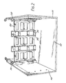
- two side panels 10, 11 are adapted to mate with a further panel 12 in the form of a base panel. Mating occurs by virtue of engagement of an elongate tongue portion on the lower side of each side panel, for example tongue 14 of side panel 11, with a slot extending upwardly at an edge of the base panel, such as slot 15 for panel 12. Engagement of tongue and slot is sufficient to support the side panels substantially normal to the base panel, such as side panel 10.
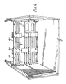
- a mother-board support member 20 (Figure 2) is arranged to be introduced between side panels 10, 11 in a plane normal thereto and to interlock therewith. Interlock is provided by the entry of a right angled flange projection 30 ( Figure 3) of support member 20 with a receptor portion 31 of side panel 11. As may be more clearly seen in Figure 1, receptor portion 31 is formed at substantially the level of tongue 14, hence flange 30 and receptor 31 provide a lower interlock between side panel and support member. A similar upper interlock is provided by flange 32 and receptor portion 33.
- the presence of the support member spanning the side panels serves to brace the side panels. It will further be appreciated that since the flange acts on a receptor in each side panel, the support member may be dimensioned to urge the side panels together. This has the desirable effect of locking the tongues of the side panels in the slots of base panel by forcing the tongue against the inner side wall of its slot, thereby removing any play. To this end flange portion 32 engages externally of receptor portion 33.
- Support member 20 is arranged to carry a mother-board 40 (Figure 4).
- Mother-board 40 bears a plurality of sockets, such as socket 41 adapted to receive complementary connectors on circuit cards.
- a circuit card 50 ( Figure 5) has connectors, such as connector 51 arranged to mate with sockets on the mother-board 20 when the circuit board is urged horizontally towards the mother-board.
- Slotted extensions, such as extension 52 are mounted on the inside surface of the side panels 10, 11 respectively to provide a plurality of slots, such as slots 53, and 54 which support the circuit board 50. The slots are arranged in register with the sockets on the mother-board so that a plurality of different boards may be supported interchangeably.
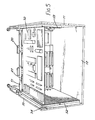
- Support member 20 (as may be more clearly seen in Figure 2) is of slotted contruction, able to carry a mother-board on each side and permit connections therebetween. Further the support member 20 is disposed towards the middle of the side panels 10, 11 ( Figure 6) to provide separate compartments 60, 61. Compartment 60 for example might be a forward compartment containing interface components such as a cathode ray tube, printer or disk drive, and compartment 61 a rearward compartment containing circuit boards. It will be appreciated that by properly arranging the support member 20, compartment 61 may be electrically screened from compartment 60.
- Side panel carries a hinged handle 62 which is fixed adjacent the support member position.
- the fixtures of the handle 62 are arranged to be on each side of the support member position to take advantage of the bracing so provided.
- Mother-board support member 20 is additionally provided with tongues, such as tongue 34 (Figure 3) which engage with complementary slots, such as slot 35, in base member 12.
- tongues such as tongue 34 ( Figure 3) which engage with complementary slots, such as slot 35, in base member 12.
- the side panels and support member may similarly engage with a top panel (not shown).
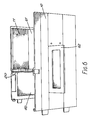
- Additional tongues such as tongue 70 ( Figure 7) on side panel 11, are arranged for engagement with complementary slots, such as slot 71, on a front panel 72.
- the front panel may be fixed into position by screws, for example a screw (not shown) passing through a hole 73 in front panel 72 to engage with a threaded portion 74 of side panel 11.
- a rear panel may be similarly fixed.
- a gasket may be laid in slot 15 ( Figure 1) before the tongue 14 of side panel 11 is introduced.
Landscapes
- Engineering & Computer Science (AREA)
- Microelectronics & Electronic Packaging (AREA)
- Mounting Of Printed Circuit Boards And The Like (AREA)
- Finger-Pressure Massage (AREA)
- Glass Compositions (AREA)
- Motor Or Generator Frames (AREA)
- Catching Or Destruction (AREA)
Priority Applications (1)
| Application Number | Priority Date | Filing Date | Title |
|---|---|---|---|
| AT89305501T ATE101470T1 (de) | 1988-06-10 | 1989-06-01 | Gehaeuseaufbau. |
Applications Claiming Priority (2)
| Application Number | Priority Date | Filing Date | Title |
|---|---|---|---|
| GB8813783 | 1988-06-10 | ||
| GB8813783A GB2219693B (en) | 1988-06-10 | 1988-06-10 | Case structure |
Publications (3)
| Publication Number | Publication Date |
|---|---|
| EP0345996A2 true EP0345996A2 (de) | 1989-12-13 |
| EP0345996A3 EP0345996A3 (de) | 1991-04-03 |
| EP0345996B1 EP0345996B1 (de) | 1994-02-09 |
Family
ID=10638428
Family Applications (1)
| Application Number | Title | Priority Date | Filing Date |
|---|---|---|---|
| EP89305501A Expired - Lifetime EP0345996B1 (de) | 1988-06-10 | 1989-06-01 | Gehäuseaufbau |
Country Status (5)
| Country | Link |
|---|---|
| US (1) | US5130887A (de) |
| EP (1) | EP0345996B1 (de) |
| AT (1) | ATE101470T1 (de) |
| DE (1) | DE68912966D1 (de) |
| GB (1) | GB2219693B (de) |
Cited By (3)
| Publication number | Priority date | Publication date | Assignee | Title |
|---|---|---|---|---|
| WO1998056223A1 (en) * | 1997-06-04 | 1998-12-10 | T.R.T. Lucent Technologies | Support frame for electronic plug-in units |
| EP1009210A3 (de) * | 1998-12-07 | 2001-01-10 | Alstom UK Limited | Ein Gehäuse for eine elektrische Schaltung |
| WO2013034434A3 (de) * | 2011-09-05 | 2013-05-23 | Fujitsu Technology Solutions Intellectual Property Gmbh | Einbaukäfig für einen computer mit einer backplane und verfahren |
Families Citing this family (9)
| Publication number | Priority date | Publication date | Assignee | Title |
|---|---|---|---|---|
| US5313369A (en) * | 1992-11-03 | 1994-05-17 | Digital Equipment Corporation | Reduced tolerance interconnect system |
| US5738226A (en) * | 1996-10-31 | 1998-04-14 | Hewlett-Packard Company | Guide piece and method for mounting to a chassis in multiple orientations |
| TW426175U (en) * | 1999-03-16 | 2001-03-11 | Hon Hai Prec Ind Co Ltd | Carrying apparatus for electric circuit board |
| US6450597B1 (en) * | 2000-03-25 | 2002-09-17 | Eurologic Systems | Wedge system shelf enclosure for network data storage system |
| WO2001073790A2 (en) * | 2000-03-25 | 2001-10-04 | Eurologic Systems | Wedge system shelf enclosure for network data storage system |
| US7505251B2 (en) * | 2005-10-28 | 2009-03-17 | International Business Machines Corporation | Actuation mechanism for mating electronic card interconnect systems |
| US8079481B2 (en) * | 2005-10-28 | 2011-12-20 | International Business Machines Corporation | Integrated frame and central electronic complex structure |
| US8070242B2 (en) * | 2006-03-24 | 2011-12-06 | Fujitsu Limited | Mounting unit and electronic apparatus |
| CN201156222Y (zh) * | 2008-01-21 | 2008-11-26 | 鸿富锦精密工业(深圳)有限公司 | 主板固定装置 |
Family Cites Families (19)
| Publication number | Priority date | Publication date | Assignee | Title |
|---|---|---|---|---|
| US3271626A (en) * | 1964-12-31 | 1966-09-06 | Patrick P Howrilka | Printed circuit card rack |
| GB1112812A (en) * | 1965-05-19 | 1968-05-08 | Alfred Imhof Ltd | Improvements in or relating to electrical or other equipment housing units or structures |
| FR1473186A (de) * | 1966-01-24 | 1967-06-01 | ||
| US3763400A (en) * | 1972-03-06 | 1973-10-02 | Interlab Inc | Control modules for electronic systems and consoles formed thereby |
| US4356531A (en) * | 1979-03-16 | 1982-10-26 | Data General, Inc. | Computer mounting assembly |
| US4277120A (en) * | 1979-05-29 | 1981-07-07 | Drake Leo O | Printed circuit board storage cabinet |
| DE7926187U1 (de) * | 1979-09-14 | 1980-01-10 | Siemens Ag, 1000 Berlin Und 8000 Muenchen | Gehäuse für Meldezentralen |
| US4301494A (en) * | 1979-09-28 | 1981-11-17 | Wescom, Inc. | Printed circuit board faceplate assembly |
| FR2521814B1 (fr) * | 1982-02-16 | 1985-09-27 | Transrack | Bac pour cartes de circuits, destine notamment aux coffrets et baies d'appareillages electroniques |
| US4426675A (en) * | 1982-04-05 | 1984-01-17 | Northern Telecom Limited | Carrier for circuit boards |
| US4527222A (en) * | 1983-02-24 | 1985-07-02 | Menasha Corporation | Precision tote box insert for holding and locating printed circuit boards or the like |
| US4574332A (en) * | 1983-06-29 | 1986-03-04 | Calabro Anthony Denis | Cage apparatus for printed circuit boards and method for preventing sharp spikes in the signal applied to said printed circuit boards |
| EP0151887A3 (de) * | 1984-01-06 | 1987-06-10 | LaFrance Corporation | Instrumentengehäuse |
| US4544066A (en) * | 1984-05-17 | 1985-10-01 | Gte Communication Systems Corporation | Printed wiring board file employing wire structural members |
| GB8523161D0 (en) * | 1985-09-19 | 1985-10-23 | Bicc Vero Electronics Ltd | Enclosure |
| GB2189083B (en) * | 1986-03-15 | 1989-11-08 | Burroughs Corp | Equipment enclosure |
| EP0262482B1 (de) * | 1986-09-30 | 1991-05-29 | Siemens Aktiengesellschaft | Gehäuse zur Aufnahme von elektrischen Baugruppenträgern |
| DE8704730U1 (de) * | 1987-03-31 | 1987-06-25 | Siemens AG, 1000 Berlin und 8000 München | Einsatz für Gestelle der elektrischen Nachrichtentechnik |
| JPH0526797Y2 (de) * | 1987-05-29 | 1993-07-07 |
-
1988
- 1988-06-10 GB GB8813783A patent/GB2219693B/en not_active Expired - Fee Related
-
1989
- 1989-06-01 EP EP89305501A patent/EP0345996B1/de not_active Expired - Lifetime
- 1989-06-01 DE DE89305501T patent/DE68912966D1/de not_active Expired - Lifetime
- 1989-06-01 AT AT89305501T patent/ATE101470T1/de not_active IP Right Cessation
-
1990
- 1990-12-19 US US07/631,178 patent/US5130887A/en not_active Expired - Fee Related
Cited By (5)
| Publication number | Priority date | Publication date | Assignee | Title |
|---|---|---|---|---|
| WO1998056223A1 (en) * | 1997-06-04 | 1998-12-10 | T.R.T. Lucent Technologies | Support frame for electronic plug-in units |
| FR2764472A1 (fr) * | 1997-06-04 | 1998-12-11 | Trt Lucent Technologies | Chassis de support de tiroirs electroniques |
| US6249441B1 (en) | 1997-06-04 | 2001-06-19 | Lucent Technologies Inc. | Support frame for electronic plug-in units |
| EP1009210A3 (de) * | 1998-12-07 | 2001-01-10 | Alstom UK Limited | Ein Gehäuse for eine elektrische Schaltung |
| WO2013034434A3 (de) * | 2011-09-05 | 2013-05-23 | Fujitsu Technology Solutions Intellectual Property Gmbh | Einbaukäfig für einen computer mit einer backplane und verfahren |
Also Published As
| Publication number | Publication date |
|---|---|
| EP0345996A3 (de) | 1991-04-03 |
| US5130887A (en) | 1992-07-14 |
| GB2219693A (en) | 1989-12-13 |
| GB8813783D0 (en) | 1988-07-13 |
| EP0345996B1 (de) | 1994-02-09 |
| DE68912966D1 (de) | 1994-03-24 |
| GB2219693B (en) | 1992-09-02 |
| ATE101470T1 (de) | 1994-02-15 |
Similar Documents
| Publication | Publication Date | Title |
|---|---|---|
| US5036313A (en) | Portable computer with improved assembly design | |
| US6049449A (en) | Computer with modular removable card cage | |
| US4977532A (en) | Industrial computer system with removable equipment drawer | |
| US5740020A (en) | Computer housing and expansion card format for consumer electronics devices | |
| US6208522B1 (en) | Computer chassis assembly with a single center pluggable midplane board | |
| EP0345996B1 (de) | Gehäuseaufbau | |
| US6724619B2 (en) | Console drive | |
| US20040032722A1 (en) | Electronics module | |
| US8023258B2 (en) | Computer enclosure and storage device module thereof | |
| WO1984004632A1 (en) | Modular housing for computer system | |
| JPH0779199B2 (ja) | 電子モジュール相互接続システム | |
| JP5331202B2 (ja) | ドライブボックス | |
| EP1298973B1 (de) | Instrument mit einer Ausnehmung für Verbinder im Gehäuse | |
| US7136283B2 (en) | Multi-computer system | |
| US20170086324A1 (en) | System and method for housing circuit boards of different physical dimensions | |
| US6222725B1 (en) | Apparatus for mounting parts and personal computer equipped with the same | |
| US5224020A (en) | Electronic apparatus having modular front and back functional units and electrical distribution unit including a fan therebetween | |
| US7236358B2 (en) | Computer system | |
| US20030161116A1 (en) | Adjustable sled module for mass storage devices | |
| JPH03151695A (ja) | プレーナ・ボードの支持装置 | |
| US20080180897A1 (en) | Expansion card carrier and method for assembling the same | |
| CN215729603U (zh) | 服务器机箱 | |
| US6046913A (en) | Panel mounted power module with adaptor mounting bracket | |
| EP1181850B1 (de) | Baugruppenträger und verfahren | |
| US20250294698A1 (en) | Chassis of an information processing device having modular panel section |
Legal Events
| Date | Code | Title | Description |
|---|---|---|---|
| PUAI | Public reference made under article 153(3) epc to a published international application that has entered the european phase |
Free format text: ORIGINAL CODE: 0009012 |
|
| AK | Designated contracting states |
Kind code of ref document: A2 Designated state(s): AT BE CH DE ES FR GB GR IT LI LU NL SE |
|
| PUAL | Search report despatched |
Free format text: ORIGINAL CODE: 0009013 |
|
| AK | Designated contracting states |
Kind code of ref document: A3 Designated state(s): AT BE CH DE ES FR GB GR IT LI LU NL SE |
|
| 17P | Request for examination filed |
Effective date: 19910816 |
|
| 17Q | First examination report despatched |
Effective date: 19921027 |
|
| RBV | Designated contracting states (corrected) |
Designated state(s): AT BE CH DE ES FR GR IT LI LU NL SE |
|
| GRAA | (expected) grant |
Free format text: ORIGINAL CODE: 0009210 |
|
| AK | Designated contracting states |
Kind code of ref document: B1 Designated state(s): AT BE CH DE ES FR GR IT LI LU NL SE |
|
| PG25 | Lapsed in a contracting state [announced via postgrant information from national office to epo] |
Ref country code: GR Free format text: LAPSE BECAUSE OF FAILURE TO SUBMIT A TRANSLATION OF THE DESCRIPTION OR TO PAY THE FEE WITHIN THE PRESCRIBED TIME-LIMIT Effective date: 19940209 Ref country code: NL Effective date: 19940209 Ref country code: LI Effective date: 19940209 Ref country code: FR Free format text: THE PATENT HAS BEEN ANNULLED BY A DECISION OF A NATIONAL AUTHORITY Effective date: 19940209 Ref country code: ES Free format text: THE PATENT HAS BEEN ANNULLED BY A DECISION OF A NATIONAL AUTHORITY Effective date: 19940209 Ref country code: CH Effective date: 19940209 Ref country code: BE Effective date: 19940209 Ref country code: AT Effective date: 19940209 Ref country code: IT Free format text: LAPSE BECAUSE OF FAILURE TO SUBMIT A TRANSLATION OF THE DESCRIPTION OR TO PAY THE FEE WITHIN THE PRE;WARNING: LAPSES OF ITALIAN PATENTS WITH EFFECTIVE DATE BEFORE 2007 MAY HAVE OCCURRED AT ANY TIME BEFORE 2007. THE CORRECT EFFECTIVE DATE MAY BE DIFFERENT FROM THE ONE RECORDED.SCRIBED TIME-LIMIT Effective date: 19940209 Ref country code: DE Effective date: 19940209 Ref country code: SE Effective date: 19940209 |
|
| REF | Corresponds to: |
Ref document number: 101470 Country of ref document: AT Date of ref document: 19940215 Kind code of ref document: T |
|
| REF | Corresponds to: |
Ref document number: 68912966 Country of ref document: DE Date of ref document: 19940324 |
|
| REG | Reference to a national code |
Ref country code: CH Ref legal event code: PL |
|
| PG25 | Lapsed in a contracting state [announced via postgrant information from national office to epo] |
Ref country code: LU Free format text: LAPSE BECAUSE OF NON-PAYMENT OF DUE FEES Effective date: 19940630 |
|
| EN | Fr: translation not filed | ||
| NLV1 | Nl: lapsed or annulled due to failure to fulfill the requirements of art. 29p and 29m of the patents act | ||
| PLBE | No opposition filed within time limit |
Free format text: ORIGINAL CODE: 0009261 |
|
| STAA | Information on the status of an ep patent application or granted ep patent |
Free format text: STATUS: NO OPPOSITION FILED WITHIN TIME LIMIT |
|
| 26N | No opposition filed |