EP0346016A2 - Senseurs biologiques - Google Patents
Senseurs biologiques Download PDFInfo
- Publication number
- EP0346016A2 EP0346016A2 EP89305574A EP89305574A EP0346016A2 EP 0346016 A2 EP0346016 A2 EP 0346016A2 EP 89305574 A EP89305574 A EP 89305574A EP 89305574 A EP89305574 A EP 89305574A EP 0346016 A2 EP0346016 A2 EP 0346016A2
- Authority
- EP
- European Patent Office
- Prior art keywords
- layer
- membrane
- sample
- block
- sensor
- Prior art date
- Legal status (The legal status is an assumption and is not a legal conclusion. Google has not performed a legal analysis and makes no representation as to the accuracy of the status listed.)
- Granted
Links
- 239000012528 membrane Substances 0.000 claims abstract description 44
- 238000002198 surface plasmon resonance spectroscopy Methods 0.000 claims abstract description 38
- 229910052751 metal Inorganic materials 0.000 claims abstract description 36
- 239000002184 metal Substances 0.000 claims abstract description 36
- 239000011521 glass Substances 0.000 claims abstract description 9
- 238000006243 chemical reaction Methods 0.000 claims abstract description 8
- 239000003989 dielectric material Substances 0.000 claims abstract description 4
- 238000013098 chemical test method Methods 0.000 claims abstract description 3
- 239000000463 material Substances 0.000 claims description 24
- 230000005855 radiation Effects 0.000 claims description 17
- 230000008878 coupling Effects 0.000 claims description 11
- 238000010168 coupling process Methods 0.000 claims description 11
- 238000005859 coupling reaction Methods 0.000 claims description 11
- 230000003287 optical effect Effects 0.000 claims description 8
- 238000012544 monitoring process Methods 0.000 claims description 5
- 230000005670 electromagnetic radiation Effects 0.000 claims description 4
- 239000012530 fluid Substances 0.000 claims description 4
- 229920000642 polymer Polymers 0.000 claims description 3
- 230000001419 dependent effect Effects 0.000 claims description 2
- 239000004519 grease Substances 0.000 claims description 2
- 239000007769 metal material Substances 0.000 claims description 2
- 239000010410 layer Substances 0.000 description 88
- 239000000523 sample Substances 0.000 description 30
- 239000010408 film Substances 0.000 description 29
- 239000000427 antigen Substances 0.000 description 9
- 102000036639 antigens Human genes 0.000 description 9
- 108091007433 antigens Proteins 0.000 description 9
- 239000004332 silver Substances 0.000 description 7
- 229910052709 silver Inorganic materials 0.000 description 7
- 238000012360 testing method Methods 0.000 description 7
- 239000007788 liquid Substances 0.000 description 5
- 230000008859 change Effects 0.000 description 4
- 239000011248 coating agent Substances 0.000 description 4
- 238000000576 coating method Methods 0.000 description 4
- 238000010586 diagram Methods 0.000 description 4
- 230000000694 effects Effects 0.000 description 4
- 238000001704 evaporation Methods 0.000 description 4
- 239000000499 gel Substances 0.000 description 4
- 230000035945 sensitivity Effects 0.000 description 4
- 239000004411 aluminium Substances 0.000 description 3
- 229910052782 aluminium Inorganic materials 0.000 description 3
- XAGFODPZIPBFFR-UHFFFAOYSA-N aluminium Chemical compound [Al] XAGFODPZIPBFFR-UHFFFAOYSA-N 0.000 description 3
- PCHJSUWPFVWCPO-UHFFFAOYSA-N gold Chemical compound [Au] PCHJSUWPFVWCPO-UHFFFAOYSA-N 0.000 description 3
- 229910052737 gold Inorganic materials 0.000 description 3
- 239000010931 gold Substances 0.000 description 3
- 150000002500 ions Chemical class 0.000 description 3
- 230000033001 locomotion Effects 0.000 description 3
- 239000000758 substrate Substances 0.000 description 3
- 230000027455 binding Effects 0.000 description 2
- 238000003754 machining Methods 0.000 description 2
- 238000000034 method Methods 0.000 description 2
- 230000010355 oscillation Effects 0.000 description 2
- 210000002966 serum Anatomy 0.000 description 2
- 239000010409 thin film Substances 0.000 description 2
- HRPVXLWXLXDGHG-UHFFFAOYSA-N Acrylamide Chemical compound NC(=O)C=C HRPVXLWXLXDGHG-UHFFFAOYSA-N 0.000 description 1
- 239000003298 DNA probe Substances 0.000 description 1
- 206010013710 Drug interaction Diseases 0.000 description 1
- 102000004190 Enzymes Human genes 0.000 description 1
- 108090000790 Enzymes Proteins 0.000 description 1
- 102000003886 Glycoproteins Human genes 0.000 description 1
- 108090000288 Glycoproteins Proteins 0.000 description 1
- 102000004856 Lectins Human genes 0.000 description 1
- 108090001090 Lectins Proteins 0.000 description 1
- 241000286209 Phasianidae Species 0.000 description 1
- 108020004518 RNA Probes Proteins 0.000 description 1
- 239000003391 RNA probe Substances 0.000 description 1
- 239000012491 analyte Substances 0.000 description 1
- 238000004458 analytical method Methods 0.000 description 1
- 230000003190 augmentative effect Effects 0.000 description 1
- 230000008901 benefit Effects 0.000 description 1
- 230000015572 biosynthetic process Effects 0.000 description 1
- 238000001514 detection method Methods 0.000 description 1
- 229910003460 diamond Inorganic materials 0.000 description 1
- 239000010432 diamond Substances 0.000 description 1
- 239000006185 dispersion Substances 0.000 description 1
- 238000007772 electroless plating Methods 0.000 description 1
- 238000009713 electroplating Methods 0.000 description 1
- 230000005686 electrostatic field Effects 0.000 description 1
- 230000008020 evaporation Effects 0.000 description 1
- 239000000835 fiber Substances 0.000 description 1
- 239000003574 free electron Substances 0.000 description 1
- 239000007789 gas Substances 0.000 description 1
- 150000004676 glycans Chemical class 0.000 description 1
- CPBQJMYROZQQJC-UHFFFAOYSA-N helium neon Chemical compound [He].[Ne] CPBQJMYROZQQJC-UHFFFAOYSA-N 0.000 description 1
- 239000000017 hydrogel Substances 0.000 description 1
- 230000002209 hydrophobic effect Effects 0.000 description 1
- 238000007654 immersion Methods 0.000 description 1
- 238000003018 immunoassay Methods 0.000 description 1
- 230000003993 interaction Effects 0.000 description 1
- 238000010849 ion bombardment Methods 0.000 description 1
- 239000002523 lectin Substances 0.000 description 1
- 230000007246 mechanism Effects 0.000 description 1
- 229910001960 metal nitrate Inorganic materials 0.000 description 1
- 229920000609 methyl cellulose Polymers 0.000 description 1
- 239000001923 methylcellulose Substances 0.000 description 1
- 235000010981 methylcellulose Nutrition 0.000 description 1
- 230000009871 nonspecific binding Effects 0.000 description 1
- 239000011368 organic material Substances 0.000 description 1
- 230000003534 oscillatory effect Effects 0.000 description 1
- -1 p.t.f.e. Substances 0.000 description 1
- 102000040430 polynucleotide Human genes 0.000 description 1
- 108091033319 polynucleotide Proteins 0.000 description 1
- 239000002157 polynucleotide Substances 0.000 description 1
- 229920001282 polysaccharide Polymers 0.000 description 1
- 239000005017 polysaccharide Substances 0.000 description 1
- 239000011241 protective layer Substances 0.000 description 1
- 102000004169 proteins and genes Human genes 0.000 description 1
- 108090000623 proteins and genes Proteins 0.000 description 1
- 230000004044 response Effects 0.000 description 1
- 150000003839 salts Chemical class 0.000 description 1
- 229920002379 silicone rubber Polymers 0.000 description 1
- 239000004945 silicone rubber Substances 0.000 description 1
- 239000002356 single layer Substances 0.000 description 1
- 239000007787 solid Substances 0.000 description 1
- 241000894007 species Species 0.000 description 1
- 239000012780 transparent material Substances 0.000 description 1
Images

Classifications
-
- G—PHYSICS
- G01—MEASURING; TESTING
- G01N—INVESTIGATING OR ANALYSING MATERIALS BY DETERMINING THEIR CHEMICAL OR PHYSICAL PROPERTIES
- G01N21/00—Investigating or analysing materials by the use of optical means, i.e. using sub-millimetre waves, infrared, visible or ultraviolet light
- G01N21/17—Systems in which incident light is modified in accordance with the properties of the material investigated
- G01N21/55—Specular reflectivity
- G01N21/552—Attenuated total reflection
- G01N21/553—Attenuated total reflection and using surface plasmons
-
- Y—GENERAL TAGGING OF NEW TECHNOLOGICAL DEVELOPMENTS; GENERAL TAGGING OF CROSS-SECTIONAL TECHNOLOGIES SPANNING OVER SEVERAL SECTIONS OF THE IPC; TECHNICAL SUBJECTS COVERED BY FORMER USPC CROSS-REFERENCE ART COLLECTIONS [XRACs] AND DIGESTS
- Y10—TECHNICAL SUBJECTS COVERED BY FORMER USPC
- Y10S—TECHNICAL SUBJECTS COVERED BY FORMER USPC CROSS-REFERENCE ART COLLECTIONS [XRACs] AND DIGESTS
- Y10S435/00—Chemistry: molecular biology and microbiology
- Y10S435/808—Optical sensing apparatus
-
- Y—GENERAL TAGGING OF NEW TECHNOLOGICAL DEVELOPMENTS; GENERAL TAGGING OF CROSS-SECTIONAL TECHNOLOGIES SPANNING OVER SEVERAL SECTIONS OF THE IPC; TECHNICAL SUBJECTS COVERED BY FORMER USPC CROSS-REFERENCE ART COLLECTIONS [XRACs] AND DIGESTS
- Y10—TECHNICAL SUBJECTS COVERED BY FORMER USPC
- Y10S—TECHNICAL SUBJECTS COVERED BY FORMER USPC CROSS-REFERENCE ART COLLECTIONS [XRACs] AND DIGESTS
- Y10S436/00—Chemistry: analytical and immunological testing
- Y10S436/805—Optical property
-
- Y—GENERAL TAGGING OF NEW TECHNOLOGICAL DEVELOPMENTS; GENERAL TAGGING OF CROSS-SECTIONAL TECHNOLOGIES SPANNING OVER SEVERAL SECTIONS OF THE IPC; TECHNICAL SUBJECTS COVERED BY FORMER USPC CROSS-REFERENCE ART COLLECTIONS [XRACs] AND DIGESTS
- Y10—TECHNICAL SUBJECTS COVERED BY FORMER USPC
- Y10T—TECHNICAL SUBJECTS COVERED BY FORMER US CLASSIFICATION
- Y10T436/00—Chemistry: analytical and immunological testing
- Y10T436/11—Automated chemical analysis
- Y10T436/110833—Utilizing a moving indicator strip or tape
Definitions
- This invention relates to sensors for use in biological, biochemical and chemical testing and in particular to immunosensors used to monitor the interaction of antibodies with their corresponding antigens.
- the properties of the surface change when a solution containing a corresponding antigen is brought into contact with the surface to thus allow the antigen to bind with the antibody.
- the change in the optical properties of the surface can be monitored with suitable apparatus.
- SPR surface plasmon resonance
- Surface plasmon resonance is the oscillation of the plasma of free electrons which exists at a metal boundary. These oscillations are affected by the refractive index of the material adjacent the metal surface and it is this that forms the basis of the sensor mechanism.
- Surface plasmon resonance may be achieved by using the evanescent wave which is generated when a P-polarised light beam is totally internally reflected at the boundary of a medium, e.g. glass, which has a high dielectric constant.
- FIG. 1 of the accompanying drawings Illustrated in Figure 1 of the accompanying drawings is a diagram of the equipment described in this paper.
- a beam 1 of light is applied from laser source (not shown) onto an internal surface 2 of a glass body 3.
- a detector (not shown) monitors the internally reflected beam 4.
- Applied to the external surface 2 of glass body 3 is a thin film 5 of metal, for example gold or silver, and applied to the film 5 is a further thin film 6 of organic material containing antibodies.
- a sample 7 containing antigen is brought into contact with the antibody film 6 to thus cause a reaction between the antigen and the antibody. If binding occurs the refractive index of the layer 6 will change owing to the increased size of the antibody molecules and this change can be detected and measured using the surface plasmon resonance technique, as will now be explained.
- the angle of incidence at which resonance occurs is affected by the refractive index of the material against the metal film 5 - i.e. the antibody layer 6 - and the angle of incidence corresponding to resonance is thus a direct measure of the state of the reaction between the antibody and the antigen.
- Increased sensitivity can be obtained by choosing an angle of incidence half way down the reflectance dip curve, where the response is substantially linear, at the beginning of the antibody/antigen reaction, and then maintaining that angle of incidence fixed and observing changes in the intensity of the reflected beam 4 with time.
- the present invention seeks to improve on the sensitivity of the basic surface plasmon resonance sensor by utilising the phenomenon of long range surface plasmon resonance. This phenomenon is described in a paper entitled “Long-range surface-plasmon modes in silver and aluminium films” by Quail, Rako and Simon in Optics Letters, vol.8, page 377.
- the present invention provides a sensor comprising a source of electro-magnetic radiation, a structure comprising a block of material transparent to the radiation from said source, a membrane of dielectric material positioned against a surface of said block, a layer of metallic material applied to that surface of said membrane opposite said block and a layer of sensitive material applied to said metallic layer, means for introducing onto the sensitive layer so as to react therewith a sample to be analysed, wherein the index of refraction of said sample and/or said sensitive layer is arranged to be equal or nearly equal to that of said membrane, and wherein the index of refraction of the material of said block is higher that that of said membrane and said sample, and means for monitoring radiation from said source which is applied to said transparent block, and which is internally reflected within the structure, the arrangement being such that the radiation causes long range surface plasmon resonance to occur, the characteristics of which resonance, as detected by said monitoring means, are dependent upon the reaction between the sample and the sensitive layer.
- the width of the resonance dip is much smaller than that for "normal" or short range surface plasmon resonance - up to ten times smaller.
- the sensitivity can thus, in principle, be greater.
- the transparent block may be made from high refractive index glass or polymer with a refractive index typically of 2. Typically, the refractive index of the first layer and the sample is 1.4.
- the fact that the block has a higher refractive index than the membrane means that a beam from the source, and incident through the block into said surface will undergo total internal reflection at the interface between the block and the membrane.
- energy is coupled into the metal layer via the membrane and sets up a surface plasmon wave in the metal layer and a corresponding evanescent wave travelling largely in the membrane.
- the block may take the shape of a prism or may be a plane rectangular block, or may be hemicylindrical or hemispherical as described in our European patent application 0305109.
- Waveguide optics such as fibre optics could be used, as described in our copending European patent application 89300544.7 filed 20th January 1989 and entitled "Biological Sensors".
- the invention is also applicable to the optical arrangements described in our copending European patent applications 89304570.8 and 89304572.4 both filed 5th May 1989, and British application 8811919.3 filed 20th May 1988, all entitled "Biological Sensors".
- the thickness of the metal layer In order to successfully utilise the long range SPR mode, the thickness of the metal layer must be reduced over that for short range SPR, typically to approximately half. For a typical layer of silver, the thickness would be 17nm.
- the thickness of the dielectric layer is critical in obtaining a single narrow resonance dip. If the layer is too thick, multiple resonances occur whereas, if it is too thin a broad dip results.
- the thickness of the dieletric layer is typically 1200nm.
- Short range surface plasmon resonance results in the generation of a pair of symmetric modes at the metal interfaces on either side of the metal layer.
- the reduced metal thickness used in the present invention allows these modes to couple together to form a single anti-symmetric mode which has a greatly reduced half-width at resonance. This is known as the long range surface plasmon resonance mode, to distinguish it from short range surface plasmon resonance.
- combinations can occur, with both the symmetric and anti-symmetric modes existing together, giving two resonant dips, one for each mode, at difference angles of incidence.
- the membrane may be optically coupled to the block by means of a suitable optical coupling fluid or grease. If the refractive index of this intermediate coupling layer is equal to that of the membrane, then this must be taken into account when assessing the thickness of the membrane since, from the point of view of the operation of the device, the intermediate coupling layer forms part of the membrane. References herein to the "membrane" should be interpreted accordingly.
- the sensitive layer which is on the opposite side of the metal layer from the incoming radiation is usually very thin, typically 2nm thick.
- the thickness of the sensitive layer is augmented during a test by the thickness of the liquid sample, for example serum.
- the thickness of the liquid sample will generally be much greater than that of the sensitive layer; indeed, in some circumstances the sensitive layer may not exist as a separate entity at all - see below.
- the thickness of the liquid sample will be about one wavelength of the radiation - in the region of 750 nm.
- the sensitive layer may have sufficient thickness to predominate. In practice, the values of refractive index of the sample and the sensitive layer are likely to be pretty close.
- the frequency of the electromagnetic radiation will be within or near the optical region.
- Lasers are a suitable source of radiation.
- the layer applied to the metal film is described herein as an antibody layer for use in immunoassays, it will be seen that any sensitive layer whose refractive index changes upon an event occurring can be used thus to provide a sensitive detector having a wide variety of applications in the fields of biology, biochemistry and chemistry.
- the material comprising the sensitive layer may be specific to a particular entity within the sample or may be non-specific (i.e. may interact with several species of entity within the sample).
- recognition molecules such as the aforementioned antibodies which will specifically bind an analyte of interest within the sample, DNA/RNA probes which will bind with their complements in the sample liquid, or lectins, glycoproteins or enzyme substrates, all of which are capable of recognising and binding with the other partner in a bimolecular recognition pair.
- non-specific materials include hydrophobic materials, for example in the form of a monolayer of phospholipid-type molecules to capture amphipathic molecules, or hydrophilic materials which would capture polysaccharides.
- hydrophobic materials for example in the form of a monolayer of phospholipid-type molecules to capture amphipathic molecules, or hydrophilic materials which would capture polysaccharides.
- the surface of the metal film itself can form an effective non-specific binding material. Silver or gold surfaces will bind proteins or polynucleotides such as DNA or RNA without the need for any further coating and, in this case a separate sensitive layer is effectively dispensed with altogether, and the surface of the metal film used directly for the capture of entities within the sample to be tested.
- the metal film material is commonly silver or gold, usually applied by evaporation.
- the film needs to be as uniform as possible in order to cater for minute movement in the position of incidence of the incoming beam. It is assumed that a structural metal film will give the best resonance and there are various ways in which the membrane can be pretreated to improve the performance of the metal film and in particular to control the natural tendency of such films to form discontinuous islands:-
- Coating performance can also be improved by:-
- the layers comprise a high refractive index glass or polymer block 10 of material transparent to the radiation, a membrane 11 of dielectric material such as p.t.f.e., methyl cellulose or silicone rubber optically coupled to the block 10 by an intermediate coupling layer 12 of coupling fluid or gel, a thin metal layer 13, for example of silver, a sensitive layer 14, for example an antibody layer, and a liquid layer 15 taking the form of a sample, for example serum, to be tested.
- the latter layer is only present during a test and reacts with the sensitive layer to alter the refractive index of the layer to thus effect the surface plasmon resonance.
- a radiation source 8 and radiation detector 9 complete the assembly, radiation (probably light) from the source being applied through the transparent block 10 to be internally reflected at the lower surface of the block, the reflected radiation passing out through the block and to the detector 9.
- the angle ⁇ 1 of incidence of the incident beam of radiation is varied, there will be an angle at which the phenomenon of surface plasmon resonance will be observed, this manifesting itself as a sharp attenuation in the strength of the internally reflected beam.
- Normal (short range) surface plasmon resonance occurs at an angle ⁇ 1 of incidence to the normal of the reflecting metal layer of about 63 o .
- the corresponding angle is about 50 o .
- the sensitive layer In assessing the exact properties needed, it is convenient to start with the sensitive layer since it is likely that this will have a refractive index which is fixed, depending upon the particular material used. Since the sensitive layer effectively forms part of the sample from the point of view of the surface plasmon resonance, then the sample will conveniently have this same refractive index. This then sets the refractive index of the membrane to be the same as or as near as possible the same as that of the sample.
- the refractive index of the transparent block 10 needs to be higher than this so that total internal reflection takes place at the interface between the block 10 and the coupling layer 12/membrane 11.
- a suitable value for block 10 is chosen from available materials.
- the subscripts i, j 1 to 4 refer to the block 10, the membrane 11, the metal layer 13 and the sample 15 respectively. Note, however that the intermediate coupling layer 12, if present and if of the same refractive index as the membrane will effectively form part of the membrane for the purpose of this calculation. Likewise the sensitive layer will effectively form part of the sample.
- a typical antibody layer has an unreacted refractive index of approximately 1.4. This sets the refractive index of the sample and the membrane also at 1.4.
- a protective layer (not shown) of gel or similar, such as acrylamide gel or hydrogel.
- gel such as acrylamide gel or hydrogel.
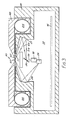
- the apparatus comprises a housing 30 having a hollow interior 31 in which is positioned a printed circuit board 16 on which is mounted the electronic circuitry associated with the apparatus.
- An aperture is formed in the top part of the housing which aperture is covered by a support plate 17 of transparent material.
- a radiation source 18 produces a collimated input beam 19 of electromagnetic radiation.
- the frequency of the radiation must be such as to result in the generation of surface plasmon waves and in practice will be within or near the visible region.
- Suitable sources include a helium neon laser or an infra red diode laser, but an ordinary light source, with suitable filters and collimators, could be used.
- the light beam 19 is applied to a mirror 20 which in turn directs the light onto a concave reflecting surface 21 and thence to the transparent support plate 17.
- the mirror 20 is driven by motor means (not shown), to rotate in an oscillatory manner between the limit positions shown by the solid and dotted lines. The result of this is that the light beam applied to the reflecting surface 21 scans backwards and forwards between the positions represented by the beams 22 (solid line) and 23 (dotted line).
- the membrane Positioned in the top surface of the support plate 17 is a membrane in the form of a continuous film 24 which is moveable from left to right in Figure 3 from a supply reel 25 to a take-up reel 26.
- the membrane takes the form of a multi-layer structure of the type shown with reference to Figure 2; in other words comprising a flexible transparent layer, corresponding to block 10, a dielectric layer, corresponding to membrane 11, a metal film layer, for example of silver, and a final layer of sensitive material, such as an antibody layer.
- the arrangement is such that the layers are in the order - transparent support plate 17 - flexible transparent layer - dielectric layer - metal film layer - sensitive layer.
- the sensitive layer is on the top when seen in Figure 3.
- the flexible transparent layer lies directly against the transparent plate 17, possibly with an optical coupling fluid in between.
- the refractive index of the plate 17 is the same as that of the flexible transparent layer so that the two effectively act as a single transparent block, as far as light is concerned.
- the flexible transparent layer in the film 24 is dispensed with, reliance being placed on the support plate 17 to act as the block 10 of Figure 2.
- Light incident from reflecting surface 21 behaves in the multi-layer structure in a similar manner to that described above with reference to Figure 2.
- the light is internally reflected at a point 27 lying on the interface between the flexible transparent layer and the dielectric layer of the film 24.
- the internally reflected light passes out of the plate 17 and is reflected off a further concave reflecting surface 28 to be incident on the sensitive surface of a light detector 29.
- the reflective surface 21 has a shape which is such as to bring light incident thereon from a range of angles to a single point 27, despite the refraction which inevitably occurs when the light enters the transparent plate 17.
- Computer analysis of the ray paths can derive a suitable shape for surface 21 to ensure that point 27 is stationary as the scanning between limit positions 22, 23 occurs.
- reflective surface 28 has a shape which is such as to bring light incident thereon from a range of angles to a single point at the sensitive area of detector 29.
- the reflective surfaces 21, 28 are formed by machining of the material, for example aluminium, of the housing 30. If the housing is not fabricated from a suitable material, the reflective surfaces 21, 28 can, of course, be formed as separate elements attached to the housing. Diamond machining of aluminium results in a highly reflective surface whose shape can be tailored, under computer control, to give whatever optical characteristics are required of it.
- the sensitive layer is one whose refractive index changes as it reacts with a sample, in the manner described above. This changes the angle of incidence at which surface plasmon resonance occurs, and thus the reaction of a sample with the sensitive layer can be monitored by observing the dip as the test proceeds.
- the film is advanced by a suitable amount, and a further test may then be carried out.
- the film 24 housed in a disposable cassette 40 which incorporates an opening 41 via which sample may be placed on the exposed film.
Landscapes
- General Health & Medical Sciences (AREA)
- General Physics & Mathematics (AREA)
- Life Sciences & Earth Sciences (AREA)
- Chemical & Material Sciences (AREA)
- Analytical Chemistry (AREA)
- Biochemistry (AREA)
- Health & Medical Sciences (AREA)
- Immunology (AREA)
- Physics & Mathematics (AREA)
- Pathology (AREA)
- Investigating Or Analysing Materials By Optical Means (AREA)
- Measuring Pulse, Heart Rate, Blood Pressure Or Blood Flow (AREA)
- Measurement And Recording Of Electrical Phenomena And Electrical Characteristics Of The Living Body (AREA)
- Investigating Or Analysing Biological Materials (AREA)
- Investigating Or Analysing Materials By The Use Of Chemical Reactions (AREA)
Priority Applications (1)
| Application Number | Priority Date | Filing Date | Title |
|---|---|---|---|
| AT89305574T ATE83076T1 (de) | 1988-06-06 | 1989-06-02 | Biosensoren. |
Applications Claiming Priority (2)
| Application Number | Priority Date | Filing Date | Title |
|---|---|---|---|
| GB888813307A GB8813307D0 (en) | 1988-06-06 | 1988-06-06 | Biological sensors |
| GB8813307 | 1988-06-06 |
Publications (3)
| Publication Number | Publication Date |
|---|---|
| EP0346016A2 true EP0346016A2 (fr) | 1989-12-13 |
| EP0346016A3 EP0346016A3 (en) | 1990-09-19 |
| EP0346016B1 EP0346016B1 (fr) | 1992-12-02 |
Family
ID=10638127
Family Applications (1)
| Application Number | Title | Priority Date | Filing Date |
|---|---|---|---|
| EP89305574A Expired - Lifetime EP0346016B1 (fr) | 1988-06-06 | 1989-06-02 | Senseurs biologiques |
Country Status (6)
| Country | Link |
|---|---|
| US (1) | US5055265A (fr) |
| EP (1) | EP0346016B1 (fr) |
| JP (1) | JPH0244230A (fr) |
| AT (1) | ATE83076T1 (fr) |
| DE (1) | DE68903688T2 (fr) |
| GB (1) | GB8813307D0 (fr) |
Cited By (13)
| Publication number | Priority date | Publication date | Assignee | Title |
|---|---|---|---|---|
| GB2247749A (en) * | 1990-09-05 | 1992-03-11 | Marconi Gec Ltd | Sensor utilising surface plasmon resonance |
| WO1992014140A1 (fr) * | 1991-02-07 | 1992-08-20 | Fisons Plc | Dispositif d'analyse |
| EP0382832B1 (fr) * | 1988-07-25 | 1994-03-23 | ARS Holding 89 N.V. | Methode d'analyse d'un ligand dans un echantillon |
| US5478755A (en) * | 1988-07-25 | 1995-12-26 | Ares Serono Research & Development Ltd. | Long range surface plasma resonance immunoassay |
| WO1996002823A1 (fr) * | 1994-07-20 | 1996-02-01 | Scientific Generics Limited | Detecteurs par resonance superficielle des plasmons et leur procede de mise en oeuvre |
| CN1035789C (zh) * | 1992-06-20 | 1997-09-03 | 中国科学院长春应用化学研究所 | 现场显微红外光谱电化学分析系统 |
| US5776785A (en) * | 1996-12-30 | 1998-07-07 | Diagnostic Products Corporation | Method and apparatus for immunoassay using fluorescent induced surface plasma emission |
| EP1079225A1 (fr) * | 1999-08-26 | 2001-02-28 | Fuji Photo Film Co., Ltd. | Capteur de plasmons de surface pour l'analyse d'un échantillon liquide ou d'une atmosphère humide |
| DE10145719A1 (de) * | 2001-09-17 | 2003-04-10 | Inst Chemo Biosensorik | Optischer Wasserstoff-Sensor und Verfahren zur Erfassung von Wasserstoff |
| WO2004046681A3 (fr) * | 2002-11-18 | 2004-08-05 | Vir As | Biocapteur de compensation de dispersion |
| WO2005052557A1 (fr) * | 2003-11-28 | 2005-06-09 | Lumiscence A/S | Systeme d'inspection pour inspecter un specimen, sous-unites et unites associees, detecteur et microscope |
| US7319046B2 (en) | 2001-11-29 | 2008-01-15 | Konstantinos Misiakos | Integrated optoelectronic silicon biosensor for the detection of biomolecules labeled with chromophore groups or nanoparticles |
| EP1686366A3 (fr) * | 2005-01-29 | 2008-11-05 | Samsung Electronics Co., Ltd. | Dispositif de résonance plasmonique de surface longue portée en utilisant un matériau diélectrique poreux en échelle nanométrique et méthode pour le fabriquer |
Families Citing this family (89)
| Publication number | Priority date | Publication date | Assignee | Title |
|---|---|---|---|---|
| US4935346A (en) | 1986-08-13 | 1990-06-19 | Lifescan, Inc. | Minimum procedure system for the determination of analytes |
| DE69110032T2 (de) * | 1991-06-08 | 1995-12-21 | Hewlett Packard Gmbh | Verfahren und Gerät zur Feststellung und/oder Konzentrationsbestimmung von Biomolekülen. |
| JP2721616B2 (ja) * | 1992-05-26 | 1998-03-04 | 株式会社日立製作所 | 減衰全反射プリズムを用いた赤外スペクトル測定法 |
| JPH05340865A (ja) * | 1992-06-09 | 1993-12-24 | Canon Inc | 測定装置 |
| US5395587A (en) * | 1993-07-06 | 1995-03-07 | Smithkline Beecham Corporation | Surface plasmon resonance detector having collector for eluted ligate |
| WO1995006138A1 (fr) * | 1993-08-25 | 1995-03-02 | The Regents Of The University Of California | Procede microscopique pour la detection de micro-mouvements |
| US5955153A (en) * | 1993-10-01 | 1999-09-21 | Johnson & Johnson Clinical Diagnostics, Inc. | Production of carriers for surface plasmon resonance |
| GB9320310D0 (en) * | 1993-10-01 | 1993-11-17 | Kodak Ltd | Production of carriers for surface plasmon resonance |
| GB9320305D0 (en) * | 1993-10-01 | 1993-11-17 | Kodak Ltd | Production of carriers for surface plasmin resonance |
| US5606633A (en) * | 1995-06-26 | 1997-02-25 | American Research Corporation Of Virginia | Chemical detector employing surface plasmon resonance excited using an optical waveguide configured as an asymmetric waveguide coupler |
| US5815278A (en) * | 1995-10-25 | 1998-09-29 | University Of Washington | Surface plasmon resonance light pipe sensing probe and related interface optics |
| US5858799A (en) * | 1995-10-25 | 1999-01-12 | University Of Washington | Surface plasmon resonance chemical electrode |
| US5917607A (en) * | 1996-04-25 | 1999-06-29 | Fuji Photo Film Co., Ltd. | Surface plasmon sensor for multiple channel analysis |
| US5852229A (en) * | 1996-05-29 | 1998-12-22 | Kimberly-Clark Worldwide, Inc. | Piezoelectric resonator chemical sensing device |
| US6020047A (en) * | 1996-09-04 | 2000-02-01 | Kimberly-Clark Worldwide, Inc. | Polymer films having a printed self-assembling monolayer |
| US5846843A (en) * | 1996-11-18 | 1998-12-08 | The University Of Toledo | Sensor using long range surface plasmon resonance with diffraction double-grating |
| US5922550A (en) * | 1996-12-18 | 1999-07-13 | Kimberly-Clark Worldwide, Inc. | Biosensing devices which produce diffraction images |
| US6048623A (en) * | 1996-12-18 | 2000-04-11 | Kimberly-Clark Worldwide, Inc. | Method of contact printing on gold coated films |
| JP3399804B2 (ja) * | 1997-02-26 | 2003-04-21 | 富士写真フイルム株式会社 | 表面プラズモンセンサー |
| US6180288B1 (en) | 1997-03-21 | 2001-01-30 | Kimberly-Clark Worldwide, Inc. | Gel sensors and method of use thereof |
| WO1999001737A2 (fr) * | 1997-06-10 | 1999-01-14 | Calspan Corporation | Detection des matieres d'un agent chimique par utilisation d'un polymere sorbant et sonde a fluorescence |
| US6060256A (en) | 1997-12-16 | 2000-05-09 | Kimberly-Clark Worldwide, Inc. | Optical diffraction biosensor |
| US6395480B1 (en) | 1999-02-01 | 2002-05-28 | Signature Bioscience, Inc. | Computer program and database structure for detecting molecular binding events |
| IL137260A0 (en) | 1998-02-02 | 2001-07-24 | Signature Bioscience Inc | Method and apparatus for detecting molecular binding events |
| US6338968B1 (en) | 1998-02-02 | 2002-01-15 | Signature Bioscience, Inc. | Method and apparatus for detecting molecular binding events |
| US6300638B1 (en) | 1998-11-12 | 2001-10-09 | Calspan Srl Corporation | Modular probe for total internal reflection fluorescence spectroscopy |
| US6221579B1 (en) * | 1998-12-11 | 2001-04-24 | Kimberly-Clark Worldwide, Inc. | Patterned binding of functionalized microspheres for optical diffraction-based biosensors |
| US6579673B2 (en) | 1998-12-17 | 2003-06-17 | Kimberly-Clark Worldwide, Inc. | Patterned deposition of antibody binding protein for optical diffraction-based biosensors |
| US6480282B1 (en) | 1999-05-06 | 2002-11-12 | University Of Washington | Capillary surface plasmon resonance sensors and multisensors |
| JP2003507723A (ja) * | 1999-08-19 | 2003-02-25 | ザ・リージェンツ・オブ・ザ・ユニバーシティー・オブ・カリフォルニア | カンチレバーアレイブロックのパレットにより微小力を可視的に識別する装置及び方法 |
| US7167615B1 (en) | 1999-11-05 | 2007-01-23 | Board Of Regents, The University Of Texas System | Resonant waveguide-grating filters and sensors and methods for making and using same |
| US6458326B1 (en) | 1999-11-24 | 2002-10-01 | Home Diagnostics, Inc. | Protective test strip platform |
| US6399295B1 (en) | 1999-12-17 | 2002-06-04 | Kimberly-Clark Worldwide, Inc. | Use of wicking agent to eliminate wash steps for optical diffraction-based biosensors |
| US6728429B1 (en) | 2000-02-16 | 2004-04-27 | Biotell, Inc. | Optical detection |
| JP4368535B2 (ja) * | 2000-05-11 | 2009-11-18 | 富士フイルム株式会社 | 測定チップ |
| US6562625B2 (en) | 2001-02-28 | 2003-05-13 | Home Diagnostics, Inc. | Distinguishing test types through spectral analysis |
| US6525330B2 (en) | 2001-02-28 | 2003-02-25 | Home Diagnostics, Inc. | Method of strip insertion detection |
| US6541266B2 (en) | 2001-02-28 | 2003-04-01 | Home Diagnostics, Inc. | Method for determining concentration of an analyte in a test strip |
| US6885454B2 (en) * | 2001-03-28 | 2005-04-26 | Fuji Photo Film Co., Ltd. | Measuring apparatus |
| US7098041B2 (en) | 2001-12-11 | 2006-08-29 | Kimberly-Clark Worldwide, Inc. | Methods to view and analyze the results from diffraction-based diagnostics |
| US7102752B2 (en) | 2001-12-11 | 2006-09-05 | Kimberly-Clark Worldwide, Inc. | Systems to view and analyze the results from diffraction-based diagnostics |
| US20030119203A1 (en) | 2001-12-24 | 2003-06-26 | Kimberly-Clark Worldwide, Inc. | Lateral flow assay devices and methods for conducting assays |
| US8367013B2 (en) | 2001-12-24 | 2013-02-05 | Kimberly-Clark Worldwide, Inc. | Reading device, method, and system for conducting lateral flow assays |
| US20030154149A1 (en) * | 2002-02-13 | 2003-08-14 | Dilip Gajendragadkar | System and method of creating and executing a restricted stock sale plan |
| US6791690B2 (en) * | 2002-04-30 | 2004-09-14 | Agilent Technologies, Inc. | Reading dry chemical arrays |
| US7118855B2 (en) * | 2002-05-03 | 2006-10-10 | Kimberly-Clark Worldwide, Inc. | Diffraction-based diagnostic devices |
| US7771922B2 (en) | 2002-05-03 | 2010-08-10 | Kimberly-Clark Worldwide, Inc. | Biomolecule diagnostic device |
| US7223368B2 (en) | 2002-05-03 | 2007-05-29 | Kimberly-Clark Worldwide, Inc. | Diffraction-based diagnostic devices |
| US7223534B2 (en) | 2002-05-03 | 2007-05-29 | Kimberly-Clark Worldwide, Inc. | Diffraction-based diagnostic devices |
| US7485453B2 (en) * | 2002-05-03 | 2009-02-03 | Kimberly-Clark Worldwide, Inc. | Diffraction-based diagnostic devices |
| US7214530B2 (en) * | 2002-05-03 | 2007-05-08 | Kimberly-Clark Worldwide, Inc. | Biomolecule diagnostic devices and method for producing biomolecule diagnostic devices |
| US7091049B2 (en) | 2002-06-26 | 2006-08-15 | Kimberly-Clark Worldwide, Inc. | Enhanced diffraction-based biosensor devices |
| US7432105B2 (en) | 2002-08-27 | 2008-10-07 | Kimberly-Clark Worldwide, Inc. | Self-calibration system for a magnetic binding assay |
| US7285424B2 (en) | 2002-08-27 | 2007-10-23 | Kimberly-Clark Worldwide, Inc. | Membrane-based assay devices |
| US7314763B2 (en) | 2002-08-27 | 2008-01-01 | Kimberly-Clark Worldwide, Inc. | Fluidics-based assay devices |
| US7169550B2 (en) * | 2002-09-26 | 2007-01-30 | Kimberly-Clark Worldwide, Inc. | Diffraction-based diagnostic devices |
| US7122384B2 (en) * | 2002-11-06 | 2006-10-17 | E. I. Du Pont De Nemours And Company | Resonant light scattering microparticle methods |
| US7344678B2 (en) * | 2002-11-15 | 2008-03-18 | The Regents Of The University Of California | Composite sensor membrane |
| US7781172B2 (en) | 2003-11-21 | 2010-08-24 | Kimberly-Clark Worldwide, Inc. | Method for extending the dynamic detection range of assay devices |
| US7247500B2 (en) | 2002-12-19 | 2007-07-24 | Kimberly-Clark Worldwide, Inc. | Reduction of the hook effect in membrane-based assay devices |
| DE602004021685D1 (de) * | 2003-03-27 | 2009-08-06 | Corning Inc | Markierungsfreier nachweis biologischer und chemischer stoffe mittels evaneszenzfeld |
| US7851209B2 (en) | 2003-04-03 | 2010-12-14 | Kimberly-Clark Worldwide, Inc. | Reduction of the hook effect in assay devices |
| US20040197819A1 (en) | 2003-04-03 | 2004-10-07 | Kimberly-Clark Worldwide, Inc. | Assay devices that utilize hollow particles |
| US7943395B2 (en) | 2003-11-21 | 2011-05-17 | Kimberly-Clark Worldwide, Inc. | Extension of the dynamic detection range of assay devices |
| US20050112703A1 (en) | 2003-11-21 | 2005-05-26 | Kimberly-Clark Worldwide, Inc. | Membrane-based lateral flow assay devices that utilize phosphorescent detection |
| US7713748B2 (en) | 2003-11-21 | 2010-05-11 | Kimberly-Clark Worldwide, Inc. | Method of reducing the sensitivity of assay devices |
| US20050112587A1 (en) * | 2003-11-25 | 2005-05-26 | Sherrill James V. | Analyzing biological probes |
| US7943089B2 (en) | 2003-12-19 | 2011-05-17 | Kimberly-Clark Worldwide, Inc. | Laminated assay devices |
| US7815854B2 (en) | 2004-04-30 | 2010-10-19 | Kimberly-Clark Worldwide, Inc. | Electroluminescent illumination source for optical detection systems |
| US7796266B2 (en) | 2004-04-30 | 2010-09-14 | Kimberly-Clark Worldwide, Inc. | Optical detection system using electromagnetic radiation to detect presence or quantity of analyte |
| EP1754443A4 (fr) * | 2004-06-10 | 2008-10-22 | Matsushita Electric Industrial Co Ltd | Instrument de mesure d'informations d'un organisme vivant, élément standard, et procédé pour utiliser l'instrument de mesure d'information d'un organisme vivant |
| US7521226B2 (en) | 2004-06-30 | 2009-04-21 | Kimberly-Clark Worldwide, Inc. | One-step enzymatic and amine detection technique |
| US7187446B2 (en) * | 2004-07-26 | 2007-03-06 | Fuji Photo Film Co., Ltd. | Measuring apparatus |
| US7818350B2 (en) | 2005-02-28 | 2010-10-19 | Yahoo! Inc. | System and method for creating a collaborative playlist |
| US7648844B2 (en) | 2005-05-02 | 2010-01-19 | Bioscale, Inc. | Method and apparatus for detection of analyte using an acoustic device |
| US7611908B2 (en) | 2005-05-02 | 2009-11-03 | Bioscale, Inc. | Method and apparatus for therapeutic drug monitoring using an acoustic device |
| US7749445B2 (en) | 2005-05-02 | 2010-07-06 | Bioscale, Inc. | Method and apparatus for analyzing bioprocess fluids |
| US7300631B2 (en) | 2005-05-02 | 2007-11-27 | Bioscale, Inc. | Method and apparatus for detection of analyte using a flexural plate wave device and magnetic particles |
| CN100401041C (zh) * | 2005-06-09 | 2008-07-09 | 上海交通大学 | 光波导吸收式气体传感器及测量系统 |
| JP4676402B2 (ja) * | 2006-08-29 | 2011-04-27 | シャープ株式会社 | 分子検出装置及び分子検出装置を用いた洗浄装置 |
| US7949210B2 (en) * | 2006-10-09 | 2011-05-24 | Colorado School Of Mines | Silicon-compatible surface plasmon optical elements |
| KR100860701B1 (ko) * | 2007-03-14 | 2008-09-26 | 한양대학교 산학협력단 | 장거리 표면 플라즈몬 이중 금속 광도파로 센서 |
| WO2009033056A1 (fr) | 2007-09-06 | 2009-03-12 | Bioscale, Inc. | Surfaces de détection réutilisables et procédés pour leur utilisation |
| CN101246123B (zh) * | 2008-01-04 | 2012-03-14 | 清华大学 | 一种长程表面等离子波折射率检测芯片 |
| JP2012163497A (ja) * | 2011-02-08 | 2012-08-30 | Kobe Steel Ltd | 表面プラズモン共鳴測定用チップ |
| CN102183507B (zh) * | 2011-03-01 | 2012-11-21 | 吉林大学 | 一种长程表面等离子体激励表面增强拉曼散射的方法 |
| US8953168B2 (en) * | 2012-06-08 | 2015-02-10 | City University Of Hong Kong | Optical sensing devices and methods for detecting samples using the same |
| CN104697961A (zh) * | 2014-12-15 | 2015-06-10 | 天津科技大学 | 长程表面等离子体共振传感器及制备方法 |
| WO2023079677A1 (fr) * | 2021-11-05 | 2023-05-11 | 日本電信電話株式会社 | Procédé et système d'évaluation de diffusion moléculaire |
Family Cites Families (6)
| Publication number | Priority date | Publication date | Assignee | Title |
|---|---|---|---|---|
| US3526480A (en) * | 1966-12-15 | 1970-09-01 | Xerox Corp | Automated chemical analyzer |
| GB1451449A (en) * | 1972-10-09 | 1976-10-06 | Bagshawe K D | Chemical and biological analysis |
| FR2565350B1 (fr) * | 1984-06-05 | 1986-10-10 | Paris Nord Universite | Moyens propres a permettre le support, le traitement, le stockage et l'analyse automatiques en continu d'echantillons biologiques |
| GB8509491D0 (en) * | 1985-04-12 | 1985-05-15 | Plessey Co Plc | Optic waveguide biosensors |
| GB8509492D0 (en) * | 1985-04-12 | 1985-05-15 | Plessey Co Plc | Optical assay |
| GB2197065A (en) * | 1986-11-03 | 1988-05-11 | Stc Plc | Optical sensor device |
-
1988
- 1988-06-06 GB GB888813307A patent/GB8813307D0/en active Pending
-
1989
- 1989-05-30 US US07/358,612 patent/US5055265A/en not_active Expired - Lifetime
- 1989-06-02 EP EP89305574A patent/EP0346016B1/fr not_active Expired - Lifetime
- 1989-06-02 AT AT89305574T patent/ATE83076T1/de active
- 1989-06-02 DE DE8989305574T patent/DE68903688T2/de not_active Expired - Fee Related
- 1989-06-06 JP JP1143943A patent/JPH0244230A/ja active Pending
Cited By (14)
| Publication number | Priority date | Publication date | Assignee | Title |
|---|---|---|---|---|
| EP0382832B1 (fr) * | 1988-07-25 | 1994-03-23 | ARS Holding 89 N.V. | Methode d'analyse d'un ligand dans un echantillon |
| US5478755A (en) * | 1988-07-25 | 1995-12-26 | Ares Serono Research & Development Ltd. | Long range surface plasma resonance immunoassay |
| GB2247749A (en) * | 1990-09-05 | 1992-03-11 | Marconi Gec Ltd | Sensor utilising surface plasmon resonance |
| WO1992014140A1 (fr) * | 1991-02-07 | 1992-08-20 | Fisons Plc | Dispositif d'analyse |
| US5415842A (en) * | 1991-02-07 | 1995-05-16 | Fisons Plc | Surface plasmon resonance analytical device |
| CN1035789C (zh) * | 1992-06-20 | 1997-09-03 | 中国科学院长春应用化学研究所 | 现场显微红外光谱电化学分析系统 |
| WO1996002823A1 (fr) * | 1994-07-20 | 1996-02-01 | Scientific Generics Limited | Detecteurs par resonance superficielle des plasmons et leur procede de mise en oeuvre |
| US5776785A (en) * | 1996-12-30 | 1998-07-07 | Diagnostic Products Corporation | Method and apparatus for immunoassay using fluorescent induced surface plasma emission |
| EP1079225A1 (fr) * | 1999-08-26 | 2001-02-28 | Fuji Photo Film Co., Ltd. | Capteur de plasmons de surface pour l'analyse d'un échantillon liquide ou d'une atmosphère humide |
| DE10145719A1 (de) * | 2001-09-17 | 2003-04-10 | Inst Chemo Biosensorik | Optischer Wasserstoff-Sensor und Verfahren zur Erfassung von Wasserstoff |
| US7319046B2 (en) | 2001-11-29 | 2008-01-15 | Konstantinos Misiakos | Integrated optoelectronic silicon biosensor for the detection of biomolecules labeled with chromophore groups or nanoparticles |
| WO2004046681A3 (fr) * | 2002-11-18 | 2004-08-05 | Vir As | Biocapteur de compensation de dispersion |
| WO2005052557A1 (fr) * | 2003-11-28 | 2005-06-09 | Lumiscence A/S | Systeme d'inspection pour inspecter un specimen, sous-unites et unites associees, detecteur et microscope |
| EP1686366A3 (fr) * | 2005-01-29 | 2008-11-05 | Samsung Electronics Co., Ltd. | Dispositif de résonance plasmonique de surface longue portée en utilisant un matériau diélectrique poreux en échelle nanométrique et méthode pour le fabriquer |
Also Published As
| Publication number | Publication date |
|---|---|
| ATE83076T1 (de) | 1992-12-15 |
| EP0346016A3 (en) | 1990-09-19 |
| DE68903688T2 (de) | 1993-04-01 |
| EP0346016B1 (fr) | 1992-12-02 |
| JPH0244230A (ja) | 1990-02-14 |
| DE68903688D1 (de) | 1993-01-14 |
| US5055265A (en) | 1991-10-08 |
| GB8813307D0 (en) | 1988-07-13 |
Similar Documents
| Publication | Publication Date | Title |
|---|---|---|
| EP0346016B1 (fr) | Senseurs biologiques | |
| EP0305109B1 (fr) | Senseurs biologiques | |
| US5023053A (en) | Biological sensors | |
| EP0326291B1 (fr) | Capteur biologique | |
| US6870627B2 (en) | System for directed molecular interaction in surface plasmon resonance analysis | |
| EP0205236B1 (fr) | Capteurs biologiques à guides d'ondes optiques | |
| US5491556A (en) | Analytical device with variable angle of incidence | |
| US5415842A (en) | Surface plasmon resonance analytical device | |
| US5064619A (en) | Biological sensors | |
| EP0543831B1 (fr) | Dispositif analyseur | |
| US6417925B1 (en) | Surface plasmon sensor for analyzing liquid sample or humid atmosphere | |
| US5647030A (en) | Fiber optic sensor and methods and apparatus relating thereto | |
| US4877747A (en) | Optical assay: method and apparatus | |
| WO1993014392A1 (fr) | Dispositif d'analyse avec une source de lumiere polychromatique | |
| WO1992005426A1 (fr) | Detecteurs biologiques | |
| WO1993014393A1 (fr) | Dispositif d'analyse a diffraction de lumiere | |
| WO1994025850A1 (fr) | Dispositif analytique |
Legal Events
| Date | Code | Title | Description |
|---|---|---|---|
| PUAI | Public reference made under article 153(3) epc to a published international application that has entered the european phase |
Free format text: ORIGINAL CODE: 0009012 |
|
| AK | Designated contracting states |
Kind code of ref document: A2 Designated state(s): AT BE CH DE FR GB IT LI LU NL SE |
|
| PUAL | Search report despatched |
Free format text: ORIGINAL CODE: 0009013 |
|
| AK | Designated contracting states |
Kind code of ref document: A3 Designated state(s): AT BE CH DE FR GB IT LI LU NL SE |
|
| 17P | Request for examination filed |
Effective date: 19901011 |
|
| 17Q | First examination report despatched |
Effective date: 19920121 |
|
| GRAA | (expected) grant |
Free format text: ORIGINAL CODE: 0009210 |
|
| ITF | It: translation for a ep patent filed | ||
| AK | Designated contracting states |
Kind code of ref document: B1 Designated state(s): AT BE CH DE FR GB IT LI LU NL SE |
|
| PG25 | Lapsed in a contracting state [announced via postgrant information from national office to epo] |
Ref country code: AT Effective date: 19921202 |
|
| REF | Corresponds to: |
Ref document number: 83076 Country of ref document: AT Date of ref document: 19921215 Kind code of ref document: T |
|
| REF | Corresponds to: |
Ref document number: 68903688 Country of ref document: DE Date of ref document: 19930114 |
|
| ET | Fr: translation filed | ||
| PG25 | Lapsed in a contracting state [announced via postgrant information from national office to epo] |
Ref country code: GB Effective date: 19930602 |
|
| PG25 | Lapsed in a contracting state [announced via postgrant information from national office to epo] |
Ref country code: SE Effective date: 19930603 |
|
| PG25 | Lapsed in a contracting state [announced via postgrant information from national office to epo] |
Ref country code: LU Free format text: LAPSE BECAUSE OF NON-PAYMENT OF DUE FEES Effective date: 19930630 Ref country code: LI Effective date: 19930630 Ref country code: CH Effective date: 19930630 Ref country code: BE Effective date: 19930630 |
|
| PLBE | No opposition filed within time limit |
Free format text: ORIGINAL CODE: 0009261 |
|
| STAA | Information on the status of an ep patent application or granted ep patent |
Free format text: STATUS: NO OPPOSITION FILED WITHIN TIME LIMIT |
|
| 26N | No opposition filed | ||
| BERE | Be: lapsed |
Owner name: AMERSHAM INTERNATIONAL P.L.C. Effective date: 19930630 |
|
| PG25 | Lapsed in a contracting state [announced via postgrant information from national office to epo] |
Ref country code: NL Effective date: 19940101 |
|
| GBPC | Gb: european patent ceased through non-payment of renewal fee |
Effective date: 19930602 |
|
| NLV4 | Nl: lapsed or anulled due to non-payment of the annual fee | ||
| PG25 | Lapsed in a contracting state [announced via postgrant information from national office to epo] |
Ref country code: FR Effective date: 19940228 |
|
| REG | Reference to a national code |
Ref country code: CH Ref legal event code: PL |
|
| PG25 | Lapsed in a contracting state [announced via postgrant information from national office to epo] |
Ref country code: DE Effective date: 19940301 |
|
| REG | Reference to a national code |
Ref country code: FR Ref legal event code: ST |
|
| EUG | Se: european patent has lapsed |
Ref document number: 89305574.9 Effective date: 19940110 |
|
| PG25 | Lapsed in a contracting state [announced via postgrant information from national office to epo] |
Ref country code: IT Free format text: LAPSE BECAUSE OF NON-PAYMENT OF DUE FEES Effective date: 20050602 |