EP0346024B1 - Wellenlängenselektiver optischer Wellenleiterkuppler - Google Patents
Wellenlängenselektiver optischer Wellenleiterkuppler Download PDFInfo
- Publication number
- EP0346024B1 EP0346024B1 EP89305610A EP89305610A EP0346024B1 EP 0346024 B1 EP0346024 B1 EP 0346024B1 EP 89305610 A EP89305610 A EP 89305610A EP 89305610 A EP89305610 A EP 89305610A EP 0346024 B1 EP0346024 B1 EP 0346024B1
- Authority
- EP
- European Patent Office
- Prior art keywords
- optical
- coupler
- fibre
- waveguide
- optical waveguide
- Prior art date
- Legal status (The legal status is an assumption and is not a legal conclusion. Google has not performed a legal analysis and makes no representation as to the accuracy of the status listed.)
- Expired - Lifetime
Links
Images

Classifications
-
- G—PHYSICS
- G02—OPTICS
- G02B—OPTICAL ELEMENTS, SYSTEMS OR APPARATUS
- G02B6/00—Light guides; Structural details of arrangements comprising light guides and other optical elements, e.g. couplings
- G02B6/24—Coupling light guides
- G02B6/26—Optical coupling means
- G02B6/28—Optical coupling means having data bus means, i.e. plural waveguides interconnected and providing an inherently bidirectional system by mixing and splitting signals
- G02B6/293—Optical coupling means having data bus means, i.e. plural waveguides interconnected and providing an inherently bidirectional system by mixing and splitting signals with wavelength selective means
- G02B6/29331—Optical coupling means having data bus means, i.e. plural waveguides interconnected and providing an inherently bidirectional system by mixing and splitting signals with wavelength selective means operating by evanescent wave coupling
- G02B6/29332—Wavelength selective couplers, i.e. based on evanescent coupling between light guides, e.g. fused fibre couplers with transverse coupling between fibres having different propagation constant wavelength dependency
-
- G—PHYSICS
- G02—OPTICS
- G02B—OPTICAL ELEMENTS, SYSTEMS OR APPARATUS
- G02B6/00—Light guides; Structural details of arrangements comprising light guides and other optical elements, e.g. couplings
- G02B6/24—Coupling light guides
- G02B6/36—Mechanical coupling means
- G02B6/3628—Mechanical coupling means for mounting fibres to supporting carriers
- G02B6/3632—Mechanical coupling means for mounting fibres to supporting carriers characterised by the cross-sectional shape of the mechanical coupling means
- G02B6/3636—Mechanical coupling means for mounting fibres to supporting carriers characterised by the cross-sectional shape of the mechanical coupling means the mechanical coupling means being grooves
-
- G—PHYSICS
- G02—OPTICS
- G02F—OPTICAL DEVICES OR ARRANGEMENTS FOR THE CONTROL OF LIGHT BY MODIFICATION OF THE OPTICAL PROPERTIES OF THE MEDIA OF THE ELEMENTS INVOLVED THEREIN; NON-LINEAR OPTICS; FREQUENCY-CHANGING OF LIGHT; OPTICAL LOGIC ELEMENTS; OPTICAL ANALOGUE/DIGITAL CONVERTERS
- G02F1/00—Devices or arrangements for the control of the intensity, colour, phase, polarisation or direction of light arriving from an independent light source, e.g. switching, gating or modulating; Non-linear optics
- G02F1/01—Devices or arrangements for the control of the intensity, colour, phase, polarisation or direction of light arriving from an independent light source, e.g. switching, gating or modulating; Non-linear optics for the control of the intensity, phase, polarisation or colour
- G02F1/0128—Devices or arrangements for the control of the intensity, colour, phase, polarisation or direction of light arriving from an independent light source, e.g. switching, gating or modulating; Non-linear optics for the control of the intensity, phase, polarisation or colour based on electro-mechanical, magneto-mechanical, elasto-optic effects
- G02F1/0131—Devices or arrangements for the control of the intensity, colour, phase, polarisation or direction of light arriving from an independent light source, e.g. switching, gating or modulating; Non-linear optics for the control of the intensity, phase, polarisation or colour based on electro-mechanical, magneto-mechanical, elasto-optic effects based on photo-elastic effects, e.g. mechanically induced birefringence
- G02F1/0134—Devices or arrangements for the control of the intensity, colour, phase, polarisation or direction of light arriving from an independent light source, e.g. switching, gating or modulating; Non-linear optics for the control of the intensity, phase, polarisation or colour based on electro-mechanical, magneto-mechanical, elasto-optic effects based on photo-elastic effects, e.g. mechanically induced birefringence in optical waveguides
-
- G—PHYSICS
- G02—OPTICS
- G02F—OPTICAL DEVICES OR ARRANGEMENTS FOR THE CONTROL OF LIGHT BY MODIFICATION OF THE OPTICAL PROPERTIES OF THE MEDIA OF THE ELEMENTS INVOLVED THEREIN; NON-LINEAR OPTICS; FREQUENCY-CHANGING OF LIGHT; OPTICAL LOGIC ELEMENTS; OPTICAL ANALOGUE/DIGITAL CONVERTERS
- G02F1/00—Devices or arrangements for the control of the intensity, colour, phase, polarisation or direction of light arriving from an independent light source, e.g. switching, gating or modulating; Non-linear optics
- G02F1/29—Devices or arrangements for the control of the intensity, colour, phase, polarisation or direction of light arriving from an independent light source, e.g. switching, gating or modulating; Non-linear optics for the control of the position or the direction of light beams, i.e. deflection
- G02F1/31—Digital deflection, i.e. optical switching
- G02F1/313—Digital deflection, i.e. optical switching in an optical waveguide structure
- G02F1/3131—Digital deflection, i.e. optical switching in an optical waveguide structure in optical fibres
Definitions
- This invention relates to a wavelength selective optical waveguide coupler and particularly but not exclusively to a coupler formed from optical fibres having D-shaped cross-sections.
- a wavelength selective optical waveguide coupler by locating a pair of optical waveguides adjacent each other so as to provide a set of regularly spaced apart optical coupling regions with the optical path length between the coupling regions being greater in one waveguide than the other, which optical path lengths are a function of wavelengths of the light propagating in the waveguide.
- Light propagating in one waveguide will couple varying amounts of light into or out of the other waveguide at each coupling region dependent on the relative phase relationship of the light in the two waveguides.
- the aggregate effect for light propagating through the coupling regions will be additive only for a wavelength in which the optical path difference between coupling regions is such as to cause a relative phase shift of an integral number of 2 ⁇ radians along the length of the waveguide between the each coupling region.
- Such a coupler will couple substantially all light of a preselected wavelength from one waveguide into another whilst leaving the other wavelengths substantially unaffected. Examples of such couplers are disclosed in Patent Application No. GB2152694A.
- One of the couplers there discussed comprises first and second slab waveguides constructed in a semiconductor substrate.
- the distance between the first and second waveguides is varied periodically so as to provide the set of regularly spaced optical coupling regions.
- the waveguides are formed in a semiconductor substrate.
- the position of the first waveguide relative to the other cannot be altered so it not only involves relatively complex manufacturing techniques it is also not tunable.
- Another of the couplers there disclosed comprises two optical fibre waveguides.
- the fibres are wound in opposite senses on respective mandrels of slightly different radii for several turns.
- the path length of a turn is therefore different for each fibre.
- Optical coupling regions are formed when the turns of each optical fibre are brought together (after reducing the cladding width if necessary).
- the turns of each of the fibres when brought together meet at tangents. Coupling occurs at these tangents, and tuning may be achieved by stretching the fibres on one mandrel by increasing the radius of that mandrel.
- a disadvantage of this second known type of coupler is that due to the long path length around the mandrels, accidental path differences due to temperature fluctuations for example are difficult to eliminate, and fractional control of the radius of each mandrel must be achieved to a high level of accuracy in order to accurately tune the coupler to selectively couple the desired wavelength.
- a wavelength selective optical waveguide coupler comprising a first optical waveguide and a second optical waveguide, said waveguides being arranged so as to pass selectively a signal of a desired wavelength from one of the optical waveguides to the other optical waveguide, characterised in that the first optical waveguide is in the form of a non-coiled undulatory optical fibre extending alongside the second optical waveguide to define a set of optical coupling regions spaced apart by a predetermined distance.
- the path difference between the coupling regions can be set accurate the order of 1 ⁇ m by relatively coarse macroscopic adjustment of the fibres.
- each of the optical fibre and second optical waveguide comprises a single mode optical fibre having a cross-section which has a linear portion in each coupling region.
- the respective linear portions of the first and second waveguides will form substantially planar surfaces lying in substantially parallel planes in the coupling region.
- the optical fibres are D-fibres, that is optical fibres having a D-shaped cross-section with the core located nearer to the linear portion of the "D" cross-section of the fibre, than to the curved portion.
- Such fibres are economical to make and easily manufacturable, and provide a convenient source of single optical fibres having the preferred linear portion in each coupling region.
- the desired undulations in the optical fibre can be obtained in various ways.
- the undulatory optical fibre may be an optical fibre mounted on an undulatory surface of a substrate.
- the substrate can be accurately machined to have the desired undulatory surface.
- a fibre is mounted on the substrate it takes the form of the undulatory surface of the substrate.
- the surface of the substrate is made by forming V-grooves in the surface. This substrate may be made of silicon, and the V-grooves may then be formed by chemical etching processes.
- the first waveguide may be mounted on an elastic support and the second waveguide may be mounted on or in a substrate having a substantially planar surface.
- Spacers can be placed at regular intervals along the length of the second waveguide the undulations of the first waveguide being formed by urging the deformable, elastic support towards the second optical waveguide, thus forcing the second waveguide against the spacers and second waveguide.
- the optical fibre is embedded in the substrate with the planar surfaces of the coupling regions flush with the surface of the substrate.
- the substrate is a thermo-plastic material so the D-fibre may be embedded in the substrate by heating the substrate, and at the same time, applying a former to the fibre.
- the substrate will soften as a result of the heating.
- the former is chosen to have the desired undulatory shape the fibre will be moulded into the substrate, and will take the shape of the former.
- Means may be included for moving the optical waveguides into and out of optical coupling relationship.
- the coupler may thus be switched off by moving the waveguides out of optical coupling.
- Other means of achieving switching can be readily devised.
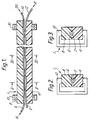
- an optical waveguide coupler 1 comprises a first D-fibre 2 which is mounted in a first substrate 4 and a second D-fibre 6 mounted in a second substrate 8.
- the substrates 4 and 8 are held together by a pair of end-clamps 10.
- Fibre 2 is an undulatory fibre and is mounted in substrate 4 the surface 12 of D-fibre 2 is substantially flush with the surface of the substrate 3.
- the fibre 6 is also mounted in substrate 8 such that the its surface 14 is substantially flush with the surface of the substrate 8.
- the surfaces of fibres 2, 6 thus come into and out of contact with another to form coupling region. In the intervening regions, where the surface of fibre 2 is separated from the surface of substrate 4, the distance between fibres 2 and 6 is too great to allow coupling to occur.
- a D-fibre fibre 22 is located adjacent the fibre 6 mounted in a substrate 8 as in the Figure 1 embodiment such that their flat surfaces are facing.
- Vibrating means 24 for example a piezo-electric transducer, is coupled to the fibre 2 such that an acoustic transverse wave may pass along the fibre 22.
- the acoustic wave passing along fibre 2 causes the fibre 22 to vibrate and thus take up an undulatory form.
- the coupler 1 may be tuned to different wavelengths. For example, a one KHz signal will give a three centimetre wavelength ripple and 100 KHz wave will give a 3 millimetre ripple approximately.
- FIG. 5 there is shown an alternative method of providing the undulatory optical fibre.
- the optical D-fibre 28 is mounted on a support 30 having deformable portion support 31 which was then pressed by clamp 10 against the firmly supported D-fibre 6 between which spacers 32, for example silica cylinders, have previously been placed.
- the portion 3 deforms as the D-fibre 28 forms undulations of period and height determined by the spacers.
- a wavelength selective optical coupler according to the present invention arranged to be operated as a switch finds application in various network architectures.
- an optical fibre may carry a wavelength multiplex to a section of D-fibre to which the fibre is spliced to form a common second optical waveguide on which undulating D-fibres cross.
- Each cross-point forms a wavelength selective optical switch according to the present invention arranged to couple a pre-selected wavelength from the D-fibre when the fibres are urged into coupling relationship, by mechanical or other means such as electrostatically.
- This arrangement can also be used to form a wavelength multiplex for transmission down an optical fibre to which the D-fibre is spliced. When any one of the undulating D-fibres is urged into contact with the D-fibre, light of a preselected wavelength can be coupled into the fibre.
- the coupler of the present invention is not in any way restricted to those formed using D-fibres and other optical fibres able to form coupling regions with another optical waveguide may be used, for example a fibre having a rectangular cross-section and on offset core.
- the second waveguide is not restricted to those formed by an optical fibre. It may be a planar waveguide formed on a substrate, for example.
Landscapes
- Physics & Mathematics (AREA)
- Nonlinear Science (AREA)
- General Physics & Mathematics (AREA)
- Optics & Photonics (AREA)
- Optical Integrated Circuits (AREA)
- Optical Couplings Of Light Guides (AREA)
- Mechanical Light Control Or Optical Switches (AREA)
- Optical Communication System (AREA)
- Optical Filters (AREA)
- Lasers (AREA)
Claims (13)
- Wellenlängenselektiver optischer Wellenleiterkoppler, der einen ersten optischen Wellenleiter (2) und einen zweiten optischen Wellenleiter (6) aufweist, wobei die Wellenleiter so angeordnet sind, um selektiv ein Signal einer gewünschten Wellenlänge von einem der optischen Wellenleiter zu dem anderen optischen Wellenleiter zu übermitteln,
dadurch gekennzeichnet, daß
der erste optische Wellenleiter in der Form einer nicht zusammengerollten gewellten optischen Faser (2) ist, die sich längs des zweiten optischen Wellenleiters (6) erstreckt, um einen Satz optischer Kopplungsbereiche festzulegen die durch eine vorbestimmte Distanz (P) voneinander beabstandet sind. - Koppler gemäß Anspruch 1, dadurch gekennzeichnet, daß die gewellte optische Faser und der weite optische Wellenleiter jeweils eine optische Einzelmode-Faser aufweist, die einen Querschnitt hat, der einen linearen Abschnitt in jedem Kopplungsbereich aufweist.
- Koppler gemäß Anspruch 2, dadurch gekennzeichnet, daß die optische Faser D-Fasern sind.
- Koppler gemäß einem der vorhergehenden Ansprüche, dadurch gekennzeichnet, daß die gewellte optische Faser (2) eine optische Faser ist, die auf eine gewellte Oberfläche eines Substrates (4) montiert ist.
- Koppler gemäß einem der Ansprüche 2 bis 3, dadurch gekennzeichnet, daß die gewellte optische Faser (2) in ein Substrat (4) eingelassen ist, wobei die koppelnden Bereiche mit der Oberfläche des Substrates ausgeglichen sind.
- Optischer Koppler gemäß Anspruch 5, dadurch gekennzeichnet, daß das Substrat ein thermoplastisches Material ist.
- Optischer Koppler gemäß einem der Ansprüche 1 bis 3, dadurch gekennzeichnet, daß der gewellte Wellenleiter (2) auf einen elastischen Träger (31) montiert ist, und daß es Abstandshalter (32) zwischen dem ersten und dem zweiten Wellenleiter gibt.
- Optischer Koppler gemäß einem der Ansprüche 1 bis 3, dadurch gekennzeichnet, daß eine vibrierende Einrichtung (24) zu dem ersten optischen Wellenleiter (2) gekoppelt ist, um eine akustische transversale Welle bereitzustellen, die längs der optischen Faser verläuft.
- Optischer Koppler gemäß Anspruch 8, dadurch gekennzeichnet, daß die vibrierende Einrichtung (24) eine variable Vibrationsfrequenz hat.
- Optischer Koppler gemäß einem der vorhergehenden Ansprüche, dadurch gekennzeichnet, daß eine Einrichtung zum Bewegen der optischen Wellenleiter in und aus der optisch koppelnden Beziehung bereitgestellt ist.
- Optischer Koppler gemäß einem der vorhergehenden Ansprüche, gekennzeichnet durch Einrichtungen zum Biegen der optischen Faser in einer Ebene, die die optischen Wellenleiter enthält.
- Optischer Wellenleiter gemäß Anspruch 1, dadurch gekennzeichnet, daß die Amplitude (H) jeder Wellung zwischen jedem Paar optischer Kopplungsbereiche die gleiche ist, und daß die gewünschte Wellenlänge eine Funktion der Amplitude (H) ist.
- Optischer Wellenleiterkoppler gemäß Anspruch 12, dadurch gekennzeichnet, daß die gewünschte Wellenlänge eine Funktion sowohl der vorbestimmten Distanz (P) als auch der Amplitude (H) ist.
Priority Applications (1)
| Application Number | Priority Date | Filing Date | Title |
|---|---|---|---|
| AT89305610T ATE92194T1 (de) | 1988-06-09 | 1989-06-02 | Wellenlaengenselektiver optischer wellenleiterkuppler. |
Applications Claiming Priority (2)
| Application Number | Priority Date | Filing Date | Title |
|---|---|---|---|
| GB888813667A GB8813667D0 (en) | 1988-06-09 | 1988-06-09 | Wavelength selective optical waveguide coupler |
| GB8813667 | 1988-06-09 |
Publications (2)
| Publication Number | Publication Date |
|---|---|
| EP0346024A1 EP0346024A1 (de) | 1989-12-13 |
| EP0346024B1 true EP0346024B1 (de) | 1993-07-28 |
Family
ID=10638356
Family Applications (1)
| Application Number | Title | Priority Date | Filing Date |
|---|---|---|---|
| EP89305610A Expired - Lifetime EP0346024B1 (de) | 1988-06-09 | 1989-06-02 | Wellenlängenselektiver optischer Wellenleiterkuppler |
Country Status (9)
| Country | Link |
|---|---|
| US (1) | US5166992A (de) |
| EP (1) | EP0346024B1 (de) |
| JP (1) | JPH03505011A (de) |
| AT (1) | ATE92194T1 (de) |
| AU (1) | AU615770B2 (de) |
| CA (1) | CA1323782C (de) |
| DE (1) | DE68907801D1 (de) |
| GB (1) | GB8813667D0 (de) |
| WO (1) | WO1989012242A1 (de) |
Families Citing this family (21)
| Publication number | Priority date | Publication date | Assignee | Title |
|---|---|---|---|---|
| GB9119734D0 (en) * | 1991-09-16 | 1991-10-30 | British Telecomm | Optical grating device |
| IL106185A (en) * | 1993-06-30 | 1997-03-18 | Scitex Corp Ltd | Optical waveguide mode coupling using mechanical wave interference |
| US5647040A (en) * | 1995-12-14 | 1997-07-08 | Corning Incorporated | Tunable optical coupler using photosensitive glass |
| US5805757A (en) * | 1996-12-10 | 1998-09-08 | Bloom; Cary | Apparatus and method for preserving optical characteristics of a fiber optic device |
| US5971629A (en) * | 1996-07-12 | 1999-10-26 | Bloom; Cary | Apparatus and method bonding optical fiber and/or device to external element using compliant material interface |
| US5815619A (en) * | 1996-12-10 | 1998-09-29 | Bloom; Cary | Fiber optic connector hermetically terminated |
| US5680495A (en) * | 1996-07-12 | 1997-10-21 | Bloom; Cary | Fiber optic device sealed by compressed metal seals and method for making the same |
| US5871559A (en) * | 1996-12-10 | 1999-02-16 | Bloom; Cary | Arrangement for automated fabrication of fiber optic devices |
| US6000858A (en) * | 1996-07-12 | 1999-12-14 | Bloom; Cary | Apparatus for, and method of, forming a low stress tight fit of an optical fiber to an external element |
| US5931983A (en) * | 1996-09-24 | 1999-08-03 | Bloom; Cary | Method of forming a fiber optic coupler by dynamically adjusting pulling speed |
| US5764348A (en) * | 1996-10-01 | 1998-06-09 | Bloom; Cary | Optical switching assembly for testing fiber optic devices |
| US6177985B1 (en) | 1996-10-01 | 2001-01-23 | Cary Bloom | Apparatus and method for testing optical fiber system components |
| US6074101A (en) * | 1996-12-10 | 2000-06-13 | Bloom; Cary | Apparatus for, and method of, forming a low stress tight fit of an optical fiber to an external element |
| US5917975A (en) * | 1996-12-10 | 1999-06-29 | Bloom; Cary | Apparatus for, and method of, forming a low stress tight fit of an optical fiber to an external element |
| US6003341A (en) | 1996-12-10 | 1999-12-21 | Bloom; Cary | Device for making fiber couplers automatically |
| JP2003156644A (ja) * | 2001-11-21 | 2003-05-30 | Seiko Epson Corp | 方向性結合器および光通信用装置 |
| US7477828B2 (en) * | 2006-01-06 | 2009-01-13 | Lockheed Martin Corporation | Optical waveguide |
| US7687899B1 (en) | 2007-08-07 | 2010-03-30 | Amkor Technology, Inc. | Dual laminate package structure with embedded elements |
| US8674485B1 (en) | 2010-12-08 | 2014-03-18 | Amkor Technology, Inc. | Semiconductor device including leadframe with downsets |
| US9513440B2 (en) | 2013-01-28 | 2016-12-06 | Harris Corporation | Actuator systems for deflecting optical waveguides, and devices for processing optical signals comprising same |
| EP4147023A4 (de) * | 2020-05-08 | 2024-05-22 | Arkwright Technologies Pty Ltd. | Optisches element zur erfassung einer veränderung einer dehnung |
Citations (1)
| Publication number | Priority date | Publication date | Assignee | Title |
|---|---|---|---|---|
| EP0165773A2 (de) * | 1984-06-20 | 1985-12-27 | The Board Of Trustees Of The Leland Stanford Junior University | Brückenfilter mit hintereinander geschalteten Fibern |
Family Cites Families (20)
| Publication number | Priority date | Publication date | Assignee | Title |
|---|---|---|---|---|
| GB1574044A (en) * | 1977-02-01 | 1980-09-03 | Plessey Co Ltd | Method of connecting optical fibres |
| GB2046466B (en) * | 1979-01-24 | 1983-02-16 | Bicc Ltd | Joining optical fibres using magnifier |
| US4347090A (en) * | 1980-10-24 | 1982-08-31 | Bunnell Plastics, Inc. | Process for forming laminated pipe |
| US4444458A (en) * | 1981-05-26 | 1984-04-24 | Gould Inc. | Substrate ruggedized optical fiber apparatus |
| FR2506954A1 (fr) * | 1981-06-01 | 1982-12-03 | Centre Nat Rech Scient | Dispositif de couplage de fibres optiques et son procede de fabrication |
| US4479701A (en) * | 1981-12-01 | 1984-10-30 | Leland Stanford Junior University | Dual coupler fiber optic recirculating memory |
| US4586783A (en) * | 1983-05-23 | 1986-05-06 | Raychem Corporation | Signal coupler for buffered optical fibers |
| GB2152694B (en) * | 1984-01-05 | 1987-06-24 | Standard Telephones Cables Ltd | Wavelength selective optical waveguide coupler |
| US4589725A (en) * | 1984-03-28 | 1986-05-20 | Andrew Corporation | Optical-fiber directional coupler using boron oxide as interstitial material |
| FR2577590B1 (fr) * | 1985-02-14 | 1988-07-29 | Fealfrance Sa | Procede de fabrication de panneaux armes en matiere isolante. |
| US4594121A (en) * | 1985-03-07 | 1986-06-10 | Tektronix, Inc. | Method of splicing elongate members of generally cylindrical form in a predetermined position |
| US4673270A (en) * | 1985-06-28 | 1987-06-16 | Amp Incorporated | Channel add/drop filter-coupler |
| US4883335A (en) * | 1986-01-06 | 1989-11-28 | American Telephone And Telegraph Company | Single-mode optical fiber tap |
| US4832437A (en) * | 1986-01-17 | 1989-05-23 | The Board Of Trustees Of The Leland Stanford Junior University | Fiber optic inter-mode coupling single side band frequency shifter |
| DE3789246T2 (de) * | 1986-01-17 | 1994-07-21 | Univ Leland Stanford Junior | Faseroptischer modengekoppelter Einseitenbandfrequenzschieber. |
| DE3601762C1 (de) * | 1986-01-22 | 1987-04-30 | Happich Gmbh Gebr | Sonnenblende fuer Fahrzeuge |
| US4749249A (en) * | 1986-02-19 | 1988-06-07 | United Technologies Corporation | Fiber-optic rotary coupler with lossy microbends |
| DE3788237D1 (de) * | 1986-03-07 | 1994-01-05 | Siemens Ag | Verfahren zum positionsgerechten Fügen von Lichtwellenleitern in Koppelstellen und Koppelelement für Lichtwellenleiter-Schalter. |
| US4869570A (en) * | 1987-02-21 | 1989-09-26 | Nippon Telegraph And Telephone Corporation | Fiber coupler and method and apparatus for manufacturing the same |
| US4789217A (en) * | 1987-05-05 | 1988-12-06 | Tektronix, Inc. | Method of and apparatus for securing elongate members of generally cylindrical form in end-to-end relationship |
-
1988
- 1988-06-09 GB GB888813667A patent/GB8813667D0/en active Pending
-
1989
- 1989-06-02 AT AT89305610T patent/ATE92194T1/de not_active IP Right Cessation
- 1989-06-02 EP EP89305610A patent/EP0346024B1/de not_active Expired - Lifetime
- 1989-06-02 DE DE8989305610T patent/DE68907801D1/de not_active Expired - Lifetime
- 1989-06-07 JP JP1507018A patent/JPH03505011A/ja active Pending
- 1989-06-07 US US07/602,251 patent/US5166992A/en not_active Expired - Fee Related
- 1989-06-07 WO PCT/GB1989/000616 patent/WO1989012242A1/en not_active Ceased
- 1989-06-07 AU AU38367/89A patent/AU615770B2/en not_active Ceased
- 1989-06-09 CA CA000602371A patent/CA1323782C/en not_active Expired - Fee Related
Patent Citations (1)
| Publication number | Priority date | Publication date | Assignee | Title |
|---|---|---|---|---|
| EP0165773A2 (de) * | 1984-06-20 | 1985-12-27 | The Board Of Trustees Of The Leland Stanford Junior University | Brückenfilter mit hintereinander geschalteten Fibern |
Also Published As
| Publication number | Publication date |
|---|---|
| EP0346024A1 (de) | 1989-12-13 |
| AU615770B2 (en) | 1991-10-10 |
| US5166992A (en) | 1992-11-24 |
| CA1323782C (en) | 1993-11-02 |
| DE68907801D1 (de) | 1993-09-02 |
| ATE92194T1 (de) | 1993-08-15 |
| AU3836789A (en) | 1990-01-05 |
| JPH03505011A (ja) | 1991-10-31 |
| WO1989012242A1 (en) | 1989-12-14 |
| GB8813667D0 (en) | 1988-07-13 |
Similar Documents
| Publication | Publication Date | Title |
|---|---|---|
| EP0346024A1 (de) | Wellenlängenselektiver optischer Wellenleiterkuppler | |
| US4723827A (en) | Fiber optic switch and discretely variable delay line | |
| US4673270A (en) | Channel add/drop filter-coupler | |
| US6501875B2 (en) | Mach-Zehnder inteferometers and applications based on evanescent coupling through side-polished fiber coupling ports | |
| US4720160A (en) | Optical resonant cavity filters | |
| US5341444A (en) | Polarization compensated integrated optical filters and multiplexers | |
| US4493528A (en) | Fiber optic directional coupler | |
| US4881791A (en) | Optical device | |
| US20020076150A1 (en) | Evanescent optical coupling between a waveguide formed on a substrate and a side-polished fiber | |
| EP0126065B1 (de) | Kontinuierlich einstellbare faseroptikverzögerungslinie | |
| US20090226129A1 (en) | Integrated optical signal handling device | |
| US5796906A (en) | Optical planar waveguide notch filters | |
| US6856732B2 (en) | Method and apparatus for adding/droping optical signals in a semiconductor substrate | |
| EP0149891A2 (de) | Koppler für optische Wellenleiter | |
| US20050152649A1 (en) | Device for directional and wavelength-selective optical coupling | |
| US20020018619A1 (en) | Device for adjustable chirping in-fiber bragg gratings and method for producing same | |
| JP2000147286A (ja) | 光導波路及びその製造方法 | |
| JPH1031121A (ja) | グレ−ティングを用いた導波路型の合分波器 | |
| US6522811B1 (en) | Arrayed waveguide grating | |
| WO2002001262A2 (en) | Evanescent optical coupling between a waveguide formed on a substrate and a side-polished fiber | |
| JPH01177001A (ja) | ファイバ形光合分波器 | |
| JP2025128969A (ja) | 光導波路素子 | |
| Toba et al. | Optical filters and couplers | |
| Carenco | Lupu et al. | |
| JPS62189406A (ja) | 導波形光分波器 |
Legal Events
| Date | Code | Title | Description |
|---|---|---|---|
| PUAI | Public reference made under article 153(3) epc to a published international application that has entered the european phase |
Free format text: ORIGINAL CODE: 0009012 |
|
| AK | Designated contracting states |
Kind code of ref document: A1 Designated state(s): AT BE CH DE ES FR GB GR IT LI LU NL SE |
|
| 17P | Request for examination filed |
Effective date: 19900521 |
|
| 17Q | First examination report despatched |
Effective date: 19920428 |
|
| GRAA | (expected) grant |
Free format text: ORIGINAL CODE: 0009210 |
|
| AK | Designated contracting states |
Kind code of ref document: B1 Designated state(s): AT BE CH DE ES FR GB GR IT LI LU NL SE |
|
| PG25 | Lapsed in a contracting state [announced via postgrant information from national office to epo] |
Ref country code: BE Effective date: 19930728 Ref country code: SE Effective date: 19930728 Ref country code: ES Free format text: THE PATENT HAS BEEN ANNULLED BY A DECISION OF A NATIONAL AUTHORITY Effective date: 19930728 Ref country code: FR Effective date: 19930728 Ref country code: DE Effective date: 19930728 Ref country code: GR Free format text: LAPSE BECAUSE OF FAILURE TO SUBMIT A TRANSLATION OF THE DESCRIPTION OR TO PAY THE FEE WITHIN THE PRESCRIBED TIME-LIMIT Effective date: 19930728 Ref country code: NL Effective date: 19930728 Ref country code: LI Effective date: 19930728 Ref country code: AT Effective date: 19930728 Ref country code: CH Effective date: 19930728 Ref country code: IT Free format text: LAPSE BECAUSE OF FAILURE TO SUBMIT A TRANSLATION OF THE DESCRIPTION OR TO PAY THE FEE WITHIN THE PRE;WARNING: LAPSES OF ITALIAN PATENTS WITH EFFECTIVE DATE BEFORE 2007 MAY HAVE OCCURRED AT ANY TIME BEFORE 2007. THE CORRECT EFFECTIVE DATE MAY BE DIFFERENT FROM THE ONE RECORDED.SCRIBED TIME-LIMIT Effective date: 19930728 |
|
| REF | Corresponds to: |
Ref document number: 92194 Country of ref document: AT Date of ref document: 19930815 Kind code of ref document: T |
|
| REF | Corresponds to: |
Ref document number: 68907801 Country of ref document: DE Date of ref document: 19930902 |
|
| REG | Reference to a national code |
Ref country code: CH Ref legal event code: PL |
|
| EN | Fr: translation not filed | ||
| NLV1 | Nl: lapsed or annulled due to failure to fulfill the requirements of art. 29p and 29m of the patents act | ||
| PLBE | No opposition filed within time limit |
Free format text: ORIGINAL CODE: 0009261 |
|
| STAA | Information on the status of an ep patent application or granted ep patent |
Free format text: STATUS: NO OPPOSITION FILED WITHIN TIME LIMIT |
|
| PG25 | Lapsed in a contracting state [announced via postgrant information from national office to epo] |
Ref country code: LU Free format text: LAPSE BECAUSE OF NON-PAYMENT OF DUE FEES Effective date: 19940630 |
|
| 26N | No opposition filed | ||
| PGFP | Annual fee paid to national office [announced via postgrant information from national office to epo] |
Ref country code: GB Payment date: 20000523 Year of fee payment: 12 |
|
| REG | Reference to a national code |
Ref country code: GB Ref legal event code: 732E |
|
| PG25 | Lapsed in a contracting state [announced via postgrant information from national office to epo] |
Ref country code: GB Free format text: LAPSE BECAUSE OF NON-PAYMENT OF DUE FEES Effective date: 20010602 |
|
| GBPC | Gb: european patent ceased through non-payment of renewal fee |
Effective date: 20010602 |