EP0346096A1 - Stützlager - Google Patents
Stützlager Download PDFInfo
- Publication number
- EP0346096A1 EP0346096A1 EP89305740A EP89305740A EP0346096A1 EP 0346096 A1 EP0346096 A1 EP 0346096A1 EP 89305740 A EP89305740 A EP 89305740A EP 89305740 A EP89305740 A EP 89305740A EP 0346096 A1 EP0346096 A1 EP 0346096A1
- Authority
- EP
- European Patent Office
- Prior art keywords
- roller
- rotatable
- bearing
- bearing according
- track
- Prior art date
- Legal status (The legal status is an assumption and is not a legal conclusion. Google has not performed a legal analysis and makes no representation as to the accuracy of the status listed.)
- Withdrawn
Links
- 239000007769 metal material Substances 0.000 claims abstract description 3
- 230000001747 exhibiting effect Effects 0.000 abstract description 2
- 238000010276 construction Methods 0.000 description 4
- 238000009877 rendering Methods 0.000 description 2
- 229910000831 Steel Inorganic materials 0.000 description 1
- 230000015556 catabolic process Effects 0.000 description 1
- 230000000694 effects Effects 0.000 description 1
- 210000003141 lower extremity Anatomy 0.000 description 1
- 239000000463 material Substances 0.000 description 1
- 229920003023 plastic Polymers 0.000 description 1
- 239000004033 plastic Substances 0.000 description 1
- 230000002028 premature Effects 0.000 description 1
- 239000010959 steel Substances 0.000 description 1
Images

Classifications
-
- F—MECHANICAL ENGINEERING; LIGHTING; HEATING; WEAPONS; BLASTING
- F16—ENGINEERING ELEMENTS AND UNITS; GENERAL MEASURES FOR PRODUCING AND MAINTAINING EFFECTIVE FUNCTIONING OF MACHINES OR INSTALLATIONS; THERMAL INSULATION IN GENERAL
- F16C—SHAFTS; FLEXIBLE SHAFTS; ELEMENTS OR CRANKSHAFT MECHANISMS; ROTARY BODIES OTHER THAN GEARING ELEMENTS; BEARINGS
- F16C29/00—Bearings for parts moving only linearly
- F16C29/04—Ball or roller bearings
- F16C29/045—Ball or roller bearings having rolling elements journaled in one of the moving parts
Definitions
- This invention relates to bearings arranged to support relatively heavy items for movement along a track, for example, a movable part of a machine tool along a rectilinear rail of substantially circular cross section.
- An object of the present invention is to provide support bearings which avoid the known constructions just mentioned and which, since they do not exhibit relatively thin rotatable shells, can reliably support considerably larger loads than is possible for the known constructions.
- the support bearing that is illustrated therein is mounted in a body 1 that might, purely for example, be a relatively heavy part of a machine tool that is movable rectilinearly along a 50 mm ball bush shaft or rail 4 of circular cross-section that is secured to mountings 6 on a base 5 by a number of relatively spaced, parallel and substantially vertically extending M12 bolts 7.
- a 50 mm roller 3 is rotatable about a substantially horizontal axis in a cylindrical cavity in the body 1 and comprises a central portion 8 exhibiting a gently curved concaved contact surface, the central portion 8 being flanked by two symmetrically identical stop portions 9 and these stop portions 9, in turn, being flanked by two symmetrically identical stub shafts 10.
- the complete roller 3 is advantageously formed from high tensile steel and is freely rotatable about its own longitudinal axis due to the fact that each of the symmetrically identical stub shafts 10 is surrounded by a corresponding needle bearing 2 whose outer race is accommodated in one end of the aforementioned cylindrical cavity in the body 1.
- the needle bearings 2 are commercially available items that advantageously, but not essentially, are formed from the metallic material known as "40-52-36".
- an arched rebate 11 is formed in the base of the body 1 so as to extend perpendicular to the plane of Fig. 1.
- the rebate 11 has a concave curvature which, when the body 1 is mounted on the rail 4, is concentric with that rail 4, only a relatively small clearance being left between the convex surface of the rail 4 and the concave interior of the rebate 11.
- the central portion 8 of the roller 3 projects through an opening in the top of the rebate 11 and contacts an upper region of the rail 4.
- the convex curvature of the rail 4 and the concave curvature of the central portion 8 of the roller 3 substantially match one another although it has been found desirable that the concave curvature of the central portion 8 of the roller 3 should not have precisely the same radius as that of the convex surface of the rail 4 but should exhibit a so-called conformity radius that may be of the order of 1.06 x the radius of the shaft or rail 4.
- conformity radius may be of the order of 1.06 x the radius of the shaft or rail 4.
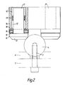
- a body 14 equivalent to the previously mentioned body 1 exhibits two laterally spaced apart but parallel and substantially vertically extending cylindrical cavities in each of which is rotatably disposed a corresponding plain shaft 21.
- each shaft 21 integrally carries an enlarged diameter head 16 and this head 16 has a lower extremity in the form of a tapering portion 17 whose downwardly tapering surface is of a concave curved configuration whose radius matches that of the convex surface of the rail 4 or which, preferably, has the aforementioned conformity radius which may be 1.06 x the radius of the rail 4.
- each shaft 21 is surrounded in the corresponding cylindrical cavity by upper and lower needle bearings 12, a synthetic plastics collar 13 also surrounding the shaft 21 in spacing relationship between the upper and lower needle bearings 12.
- a ring 18 surrounds each shaft 21 just beneath the corresponding lower needle bearing 12 and a second ring 19 also surrounds each shaft 21 in abutment with the upper surface of the enlarged head 16 thereof.
- a commercially available roller thrust race 15 is interposed between each upper ring 18 and the corresponding lower second ring 19 and it will immediately be clear from Fig. 2 of the drawings that the body 14 is movable rectilinearly along the rail 4 in a direction perpendicular to the plane of Fig. 2 with the two shafts 21 freely rotating in opposite directions.
- Support bearings of the kind which have been described may, and usually will, of course, be employed in multiple arrangements with spacing between them along the rail 4 and, in some cases, with parallel rails 4 each co-operating with one or more such support bearing.
- support bearings in accordance with the invention have the considerable advantage that the needle and thrust bearings which they exhibit are commercially available items that can be readily obtained from stockists of such materials, thus rendering the complete support bearings relatively inexpensive to produce.
Landscapes
- Engineering & Computer Science (AREA)
- General Engineering & Computer Science (AREA)
- Mechanical Engineering (AREA)
- Bearings For Parts Moving Linearly (AREA)
Applications Claiming Priority (2)
| Application Number | Priority Date | Filing Date | Title |
|---|---|---|---|
| GB8813413 | 1988-06-07 | ||
| GB888813413A GB8813413D0 (en) | 1988-06-07 | 1988-06-07 | Support bearings |
Publications (1)
| Publication Number | Publication Date |
|---|---|
| EP0346096A1 true EP0346096A1 (de) | 1989-12-13 |
Family
ID=10638189
Family Applications (1)
| Application Number | Title | Priority Date | Filing Date |
|---|---|---|---|
| EP89305740A Withdrawn EP0346096A1 (de) | 1988-06-07 | 1989-06-07 | Stützlager |
Country Status (2)
| Country | Link |
|---|---|
| EP (1) | EP0346096A1 (de) |
| GB (1) | GB8813413D0 (de) |
Cited By (1)
| Publication number | Priority date | Publication date | Assignee | Title |
|---|---|---|---|---|
| EP3656956B1 (de) * | 2018-11-26 | 2023-12-06 | Sotralu (Société par Actions Simplifiée) | Schlitten für schiebeflügel, schiebeflügel und gesamtes öffnungselement, das einen solchen schlitten umfasst |
Citations (5)
| Publication number | Priority date | Publication date | Assignee | Title |
|---|---|---|---|---|
| GB845675A (en) * | 1957-10-10 | 1960-08-24 | Anderson Co | Bearing structure |
| GB1090087A (en) * | 1965-04-09 | 1967-11-08 | Herman Rudolf Zeidler | Shaft supporting devices |
| CH512338A (de) * | 1970-11-16 | 1971-09-15 | Pfister Werner | Vorrichtung zur Führung eines Tragkörpers einer Reissschiene |
| FR2208068A1 (de) * | 1972-11-07 | 1974-06-21 | Krahenbuhl Roland | |
| AU548032B2 (en) * | 1982-02-09 | 1985-11-21 | Anthony Bearings Pty Ltd | Bearing |
-
1988
- 1988-06-07 GB GB888813413A patent/GB8813413D0/en active Pending
-
1989
- 1989-06-07 EP EP89305740A patent/EP0346096A1/de not_active Withdrawn
Patent Citations (5)
| Publication number | Priority date | Publication date | Assignee | Title |
|---|---|---|---|---|
| GB845675A (en) * | 1957-10-10 | 1960-08-24 | Anderson Co | Bearing structure |
| GB1090087A (en) * | 1965-04-09 | 1967-11-08 | Herman Rudolf Zeidler | Shaft supporting devices |
| CH512338A (de) * | 1970-11-16 | 1971-09-15 | Pfister Werner | Vorrichtung zur Führung eines Tragkörpers einer Reissschiene |
| FR2208068A1 (de) * | 1972-11-07 | 1974-06-21 | Krahenbuhl Roland | |
| AU548032B2 (en) * | 1982-02-09 | 1985-11-21 | Anthony Bearings Pty Ltd | Bearing |
Non-Patent Citations (1)
| Title |
|---|
| MACHINE DESIGN, vol. 33, no. 24, 23rd November 1961, page 116; "Crosswise rollers support shaft" * |
Cited By (1)
| Publication number | Priority date | Publication date | Assignee | Title |
|---|---|---|---|---|
| EP3656956B1 (de) * | 2018-11-26 | 2023-12-06 | Sotralu (Société par Actions Simplifiée) | Schlitten für schiebeflügel, schiebeflügel und gesamtes öffnungselement, das einen solchen schlitten umfasst |
Also Published As
| Publication number | Publication date |
|---|---|
| GB8813413D0 (en) | 1988-07-13 |
Similar Documents
| Publication | Publication Date | Title |
|---|---|---|
| DE102012004329B4 (de) | Anordnung zur Lagerung von gegeneinander verdrehbaren Teilen einer Energieanlage | |
| KR101558913B1 (ko) | 샤프트 롤링 요소들 상에 안내된 케이지를 갖는 스크류 사출성형기를 위한 스러스트 롤링 베어링 | |
| US5234388A (en) | Differential with gear support plate and bearing | |
| EP1957811B1 (de) | Radialwälzlager, insbesondere einreihiges rillenwälzlager | |
| WO1985001783A1 (en) | Conveyor chain | |
| EP0739833A1 (de) | Förderer | |
| WO2006057258B1 (ja) | 保持器付自動調心ころ軸受及び自動調心ころ軸受用保持器の製造方法 | |
| EP0346096A1 (de) | Stützlager | |
| GB1275335A (en) | Bearing cage | |
| US3765733A (en) | Bearing assembly | |
| EP0520968A1 (de) | Rollenkäfig | |
| US4368931A (en) | Self aligning press in bearing structures | |
| EP0138764A2 (de) | Lagervorrichtung für Radachsen | |
| KR860002663A (ko) | 직선접동용 로울러 베어링과 직선 안내장치 | |
| US4462524A (en) | Endless chain conveyor | |
| US4266662A (en) | Trough roller assembly | |
| GB1517615A (en) | Bearing assemblies | |
| KR940021147A (ko) | 프레스다이세트 및 이를 구동시키는 프레스기계 | |
| DE2333336A1 (de) | Laengsfuehrungslager | |
| GB957612A (en) | Improvements in or relating to machine bearings | |
| DE2346137A1 (de) | Einrichtung zur uebertragung der drehbewegung an eine zylindrische trommel od. dgl | |
| EP0621219A1 (de) | Förderer | |
| DE7302217U (de) | Lager für Kreuzgelenkzapfen | |
| EP0964175A3 (de) | Hydrodynamisches Gaslager und Verfahren zur Herstellung eines solchen Lagers | |
| DE102022110311A1 (de) | Axiallageranordnung mit von einem mehrteiligen Lagerkäfig eingefassten Lagerrollen |
Legal Events
| Date | Code | Title | Description |
|---|---|---|---|
| PUAI | Public reference made under article 153(3) epc to a published international application that has entered the european phase |
Free format text: ORIGINAL CODE: 0009012 |
|
| AK | Designated contracting states |
Kind code of ref document: A1 Designated state(s): AT BE CH DE ES FR GB GR IT LI LU NL SE |
|
| 17P | Request for examination filed |
Effective date: 19900608 |
|
| 17Q | First examination report despatched |
Effective date: 19920302 |
|
| STAA | Information on the status of an ep patent application or granted ep patent |
Free format text: STATUS: THE APPLICATION IS DEEMED TO BE WITHDRAWN |
|
| 18D | Application deemed to be withdrawn |
Effective date: 19920714 |