EP0346256A1 - Dispositif de réhabilitation in situ de canalisations non visitables de l'intérieur - Google Patents
Dispositif de réhabilitation in situ de canalisations non visitables de l'intérieur Download PDFInfo
- Publication number
- EP0346256A1 EP0346256A1 EP89440053A EP89440053A EP0346256A1 EP 0346256 A1 EP0346256 A1 EP 0346256A1 EP 89440053 A EP89440053 A EP 89440053A EP 89440053 A EP89440053 A EP 89440053A EP 0346256 A1 EP0346256 A1 EP 0346256A1
- Authority
- EP
- European Patent Office
- Prior art keywords
- module
- arms
- pipe
- rehabilitation device
- hydraulic
- Prior art date
- Legal status (The legal status is an assumption and is not a legal conclusion. Google has not performed a legal analysis and makes no representation as to the accuracy of the status listed.)
- Granted
Links
- 238000007789 sealing Methods 0.000 claims abstract description 9
- 238000002347 injection Methods 0.000 claims description 16
- 239000007924 injection Substances 0.000 claims description 16
- 238000011065 in-situ storage Methods 0.000 claims description 4
- 230000006978 adaptation Effects 0.000 claims description 3
- 230000008878 coupling Effects 0.000 claims description 3
- 238000010168 coupling process Methods 0.000 claims description 3
- 238000005859 coupling reaction Methods 0.000 claims description 3
- 239000002351 wastewater Substances 0.000 claims description 3
- 125000006850 spacer group Chemical group 0.000 claims description 2
- 239000004744 fabric Substances 0.000 claims 1
- 230000009471 action Effects 0.000 description 4
- 238000009434 installation Methods 0.000 description 4
- 230000008439 repair process Effects 0.000 description 4
- 230000008901 benefit Effects 0.000 description 2
- 238000004140 cleaning Methods 0.000 description 2
- 238000010586 diagram Methods 0.000 description 1
- 230000000694 effects Effects 0.000 description 1
- 238000009415 formwork Methods 0.000 description 1
- 239000012634 fragment Substances 0.000 description 1
- 238000009432 framing Methods 0.000 description 1
- 230000004048 modification Effects 0.000 description 1
- 238000012986 modification Methods 0.000 description 1
- 230000035515 penetration Effects 0.000 description 1
- 238000007665 sagging Methods 0.000 description 1
- 238000006467 substitution reaction Methods 0.000 description 1
Images

Classifications
-
- F—MECHANICAL ENGINEERING; LIGHTING; HEATING; WEAPONS; BLASTING
- F16—ENGINEERING ELEMENTS AND UNITS; GENERAL MEASURES FOR PRODUCING AND MAINTAINING EFFECTIVE FUNCTIONING OF MACHINES OR INSTALLATIONS; THERMAL INSULATION IN GENERAL
- F16L—PIPES; JOINTS OR FITTINGS FOR PIPES; SUPPORTS FOR PIPES, CABLES OR PROTECTIVE TUBING; MEANS FOR THERMAL INSULATION IN GENERAL
- F16L55/00—Devices or appurtenances for use in, or in connection with, pipes or pipe systems
- F16L55/16—Devices for covering leaks in pipes or hoses, e.g. hose-menders
- F16L55/162—Devices for covering leaks in pipes or hoses, e.g. hose-menders from inside the pipe
- F16L55/1645—Devices for covering leaks in pipes or hoses, e.g. hose-menders from inside the pipe a sealing material being introduced inside the pipe by means of a tool moving in the pipe
- F16L55/16455—Devices for covering leaks in pipes or hoses, e.g. hose-menders from inside the pipe a sealing material being introduced inside the pipe by means of a tool moving in the pipe a part of the tool defining, together with the inner wall of the pipe, an enclosed space into which sealing material is injected
-
- E—FIXED CONSTRUCTIONS
- E03—WATER SUPPLY; SEWERAGE
- E03F—SEWERS; CESSPOOLS
- E03F3/00—Sewer pipe-line systems
- E03F3/06—Methods of, or installations for, laying sewer pipes
-
- F—MECHANICAL ENGINEERING; LIGHTING; HEATING; WEAPONS; BLASTING
- F16—ENGINEERING ELEMENTS AND UNITS; GENERAL MEASURES FOR PRODUCING AND MAINTAINING EFFECTIVE FUNCTIONING OF MACHINES OR INSTALLATIONS; THERMAL INSULATION IN GENERAL
- F16L—PIPES; JOINTS OR FITTINGS FOR PIPES; SUPPORTS FOR PIPES, CABLES OR PROTECTIVE TUBING; MEANS FOR THERMAL INSULATION IN GENERAL
- F16L55/00—Devices or appurtenances for use in, or in connection with, pipes or pipe systems
- F16L55/18—Appliances for use in repairing pipes
-
- E—FIXED CONSTRUCTIONS
- E03—WATER SUPPLY; SEWERAGE
- E03F—SEWERS; CESSPOOLS
- E03F3/00—Sewer pipe-line systems
- E03F3/06—Methods of, or installations for, laying sewer pipes
- E03F2003/065—Refurbishing of sewer pipes, e.g. by coating, lining
Definitions
- the subject of the present invention is a device for in situ rehabilitation of rainwater or wastewater pipes which cannot be visited from the inside, because of a too small diameter, by injection under pressure of a clogging product, comprising a front module and a rear module.
- Such a device comprises in particular a central section with a diameter smaller than that of the pipe and two end sections, respectively front and rear, framing the central section, each end section having a larger diameter. larger than that of the central section and being provided, on the one hand, with guide means, on the other hand, with sealing means and, finally, with scraper means.
- this device has various drawbacks, including in particular the major drawback of not being able to circulate inside the pipes when the latter are in very bad condition, for example, during a collapse in a pipe, the latter n 'practically no longer existing at that time on a given section. Indeed, the device is then blocked in the pipeline; it is no longer a question of advancing it and it can even be very difficult to bring it out from the rear, by moving it back, without damaging, sometimes even seriously, the sealing means, which must therefore be subsequently replaced.
- this device has the drawback of not being able to adapt to different pipe diameters.
- the pipes very often have very different diameters, which can range, for example, from 150 mm to more than 300 mm.
- this device causes a very significant loss of clogging product, because it has an injection chamber, located between the two extreme sections, very large. Since this chamber must be completely filled with product, it inevitably results in a very substantial loss of said product in said pipe, which also results in forced cleaning thereof, once the device has emerged.
- this device does not allow, despite everything, the repair of large longitudinal cracks, due to an instability of the clogging product which is not sufficiently maintained in the walls of the pipe after installation.
- the general problem to be solved by the object of the present invention therefore consists in producing a device for in situ rehabilitation of pipes which cannot be visited from the inside, allowing, on the one hand, work even in pipes which have suffered collapses and where sections of walls have been torn off and no longer exist, without damaging the sealing means and, on the other hand, the adaptation to different pipe diameters.
- this device must avoid causing a consequent loss of the product, while allowing the repair of significant longitudinal cracks, and this without requiring a sophisticated installation on the surface.
- the device for in situ rehabilitation of rainwater or wastewater pipes which cannot be visited from the inside because of a too small diameter, by injection under pressure of a clogging product comprising a front module and a rear module, is characterized in that each module is provided with movable arms by means of a hydraulic means connected to a hydraulic pump, disposed on the surface, from an out-of-service position in which the arms define a diameter significantly lower than that of the pipe to be rehabilitated, in a service position in which the arms define a diameter equal to or very slightly less than that of the pipe to be rehabilitated, so that the front module, by pressing the arms on the damaged internal walls of the pipe, acts as a spacer and guide in order to restore the said pipe to its initial diameter and allow the passage of the arr module
- This is, for its part, provided at each of its two ends with sealing means delimiting with the pipe a chamber into which opens at least one inlet tube for the clogging product, connected to a pump
- each module 1, 2 is provided with arms 3, 5 movable by hydraulic means 4, 6 connected to a hydraulic pump 8, arranged on the surface, of a out of service position in which the arms 3, 5 define a diameter much smaller than that of the pipe 7 to be rehabilitated, in an in-service position in which the arms 3, 5 define an equal or very slightly smaller diameter to that of the pipe 7 to be rehabilitated, so that the front module 1, by pressing the arms 3 on the damaged internal walls of the pipe 7, plays the role of spreader and guide in order to give back to said pipe 7 its initial diameter and allow the passage of the rear module 2 which is, in turn, provided at each of its two ends with sealing means 9 delimiting with the pipe 7 a chamber 10 into which opens at least one inlet tube 11 clogging product, connected to a pump 12 disposed on the surface, for example by means of a hose 30.
- the hose 30 could, for example, be fixed to the tube 11 by means of a quick cam coupling known as CAMLOCK name.
- the front module 1 therefore plays the role of spreader and guide, thus making it possible, as shown in FIG. 2 of the appended drawings, to clear the pipe 7 and to replace the various fragments of walls which had either become detached, is collapsed in it, and this before any injection of clogging product. All supplies are made from the rear of the device, whether they are supplies to hydraulic means 4, 6 or the supply of clogging product. Thus, these supplies, in the form of hoses, cannot be damaged by sections of walls of the pipe 7 which have not yet been repaired.
- the front module 1 also allows penetration into the pipe 7, even when pieces of walls are missing, the earth itself then being placed so as to form a vault.
- the two front 1 and rear 2 modules are hinged together, for example by means of a gimbal, ball, chain or cable system, so as to per put a better passage in the pipes 7, often having angular variations and sometimes even elbows.
- the main advantage of such an articulation is that it prevents any blockage of the device in the pipe 7, which would be due to angular variations thereof (sagging, elbow, etc.).
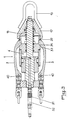
- FIGS 3 and 4 of the accompanying drawings show the front modules 1 and rear 2 of a chain rehabilitation device.
- the two front 1 and rear 2 modules are removable and are interconnected, for example by means of a set of hydraulic quick couplings 31 and hydraulic hose 32.
- the hydraulic hose 32 connects the rod central unit 19 of module 2 with primary axis 20 of module 1.
- the two front modules 1 and rear 2 are removable and are connected together, for example by bolting 26 on threaded tube 27.
- the front module 1 is provided with a hooking system 13 in the form of a hook, making it possible to tow the device to the inside the pipe 7 thanks to a pulling cable 14 and a winch 15 disposed on the surface.
- the winch 15 can advantageously be by hand.
- each hydraulic means 4, 6 is in the form of a jack provided with a return spring 16, actuating each arm 3, 5 in the service position against a stop 17 by the through a system of conical segments 33, 34 and 35, 36 cooperating with each other, the jack 4 by means of a hose 18 connected, on one side, to the hydraulic pump 8 and, on the other, at the rear end of the pierced central rod 19 of the module 2, itself connected to the primary axis 20 of the module 1, and the jack 6 by means of a hose 21 connected on one side to the hydraulic pump 8 and, on the other, at the rear end of the pierced rod 22 ( Figures 4 and 7).
- each arm 3, 5 is articulated around its end opposite to that in contact with the stop 17 around an articulation axis 40, 41.
- the hinge pin 41 of the rear module 2 can advantageously be replaced by a second system of conical segments 37, 38 cooperating with each other.
- each arm 3, 5 is held in its initial position not spaced apart by a return spring 39.
- the arms 3, 5 are provided with means for fixing plates 42, the latter allowing adaptation of the device to different pipe diameters (see FIG. 4 of the appended drawings).
- the arms 5 of the rear module 2 are advantageously six in number and are provided with perforations 23 for the passage of the clogging product. .
- the sealing means 9 are advantageously in the form, at each of the two ends of the rear module 2, of three disc-like rubber canvas seals held in place by washers 24 and supports 25 and dimensioned in such a way that they support the injection pressure of the clogging product in the injection chamber 10 of the order of 1 to 1.5 bar.
- the device according to the invention therefore operates as follows:
- the rear module 2 is lowered through the manhole 28 and it is locked with the front module 1 (thanks to the threaded tube 27 and the bolts 26).
- the winch 15 is then actuated so as to bring the rear of the module 2 to the entrance of the manhole 28.
- the arms 3 are then again pressurized to restore the part of the next pipe 7 to its initial diameter.
- the arms 5 of the rear module 2 are pressurized by starting the pump 8 on the surface which acts on the jack 6. They are pressed against the walls of the pipe 7 which have been previously replaced, by deviating by a few millimeters up to the stop 17, and the pump 12 is started up so as to inject the clogging product into the injection chamber 10, then into the walls themselves. This injection is carried out at a pressure of approximately 1 to 1.5 bar. The injection of the clogging product continues until the injection pressure stabilizes, indicating that all the cracks have been blocked. The pumps 8 and 12 are then stopped.
- the winch 15 is again actuated manually so as to advance the device according to the invention into the pipe 7 with a length slightly shorter than the injection chamber 10, this in order to obtain an overlap and to avoid that part of the pipe 7 has not been checked and treated.
- the front module 1 again comes into action, if necessary.
- the rear module 2 also comes into action.
- the two front 1 and rear 2 parts of the device are then separated and they are pulled out through the manhole 29.
- front part 1 can also be used alone when it is only a question of unblocking and cleaning a slightly damaged pipe 7, without it being necessary to inject clogging product.
- the rear module 2 can be provided with a second inlet tube 11 of clogging product, the two tubes 11 then being connected to the hose 30, when it is necessary to inject a large quantity of this product.
Landscapes
- Engineering & Computer Science (AREA)
- General Engineering & Computer Science (AREA)
- Mechanical Engineering (AREA)
- Health & Medical Sciences (AREA)
- Life Sciences & Earth Sciences (AREA)
- Hydrology & Water Resources (AREA)
- Public Health (AREA)
- Water Supply & Treatment (AREA)
- Pipe Accessories (AREA)
- Investigating Or Analyzing Materials By The Use Of Magnetic Means (AREA)
- Investigating Or Analyzing Materials By The Use Of Ultrasonic Waves (AREA)
- Pipeline Systems (AREA)
- Earth Drilling (AREA)
- Cleaning In General (AREA)
- Excavating Of Shafts Or Tunnels (AREA)
- Lining Or Joining Of Plastics Or The Like (AREA)
- Sewage (AREA)
Abstract
Description
- La présente invention a pour objet un dispositif de réhabilitation in situ de canalisations d'eaux pluviales ou usées non visitables de l'intérieur, car d'un diamètre trop réduit, par injection sous pression d'un produit colmatant, comportant un module avant et un module arrière.
- On sait que de nombreuses canalisations existantes ne sont pas directement accessibles de l'intérieur, car leur diamètre est trop réduit, mais pas non plus directement accessibles de l'extérieur, car enterrées à des profondeurs relativement importantes.
- Lorsqu'on met en évidence des fuites dans de telles canalisations, il est alors nécessaire, pour boucher les fissures, d'y faire passer un dispositif qui circule entre deux regards, afin d'effectuer la réparation.
- Or, les dispositifs existants présentent des inconvénients multiples, tels que difficultés pour réparer la partie inférieure des canalisations, difficultés pour effectuer un bouchage des fissures importantes réellement efficace et fiable dans le temps, durée importante pour remplir tout un tronçon de canalisation avec du produit colmatant, installations très conséquentes en surface, etc...
- On a alors pensé à réaliser un dispositif tentant de pallier ces inconvénients. Un tel dispositif est connu du document FR 85 04206. Ce dispositif comprend notamment un tronçon central d'un diamètre inférieur à celui de la canalisation et deux tronçons extrêmes, respectivement avant et arrière, encadrant le tronçon central, chaque tronçon extrême présentant un diamètre plus grand que celui du tronçon central et étant pourvu, d'une part, de moyens de guidage, d'autre part, de moyens d'étanchéité et, enfin, de moyens racleurs.
- Mais, ce dispositif présente différents inconvénients, dont notamment celui, majeur, de ne pas pouvoir circuler à l'intérieur des canalisations lorsque celles-ci sont en très mauvais état, par exemple, lors d'un effondrement dans une canalisation, cette dernière n'existant pratiquement plus à ce moment là sur un tronçon déterminé. En effet, le dispositif est alors bloqué dans la canalisation ; il n'est plus question de le faire avancer et il peut même être très difficile de le faire ressortir par l'arrière, en le reculant, sans endommager, parfois même gravement, les moyens d'étanchéité, qui doivent ainsi être par la suite remplacés.
- De plus, ce dispositif présente l'inconvénient de ne pas pouvoir s'adapter à des diamètres différents de canalisation. Or, on sait que les canalisations présentent très souvent des diamètres très différents, pouvant aller, par exemple, de 150 mm à plus de 300 mm.
- En outre, ce dispositif entraîne une perte très importante de produit colmatant, car il présente une chambre d'injection, située entre les deux tronçons extrêmes, très grande. Cette chambre devant être entièrement remplie de produit, il s'ensuit inévitablement une perte très conséquente dudit produit dans ladite canalisation, ce qui entraîne, en outre, un nettoyage forcé de celle-ci, une fois le dispositif ressorti.
- Enfin, ce dispositif ne permet pas, malgré tout, la réparation de grosses fissures longitudinales, du fait d'une instabilité du produit colmatant qui n'est pas suffisamment maintenu dans les parois de la canalisation après mise en place.
- De plus, une installation importante est tout de même nécessaire en surface.
- Le problème général à résoudre par l'objet de la présente invention consiste donc à réaliser un dispositif de réhabilitation in situ de canalisations non visitables de l'intérieur permettant, d'une part, le travail même dans les canalisations ayant subi des effondrements et où des pans de parois ont été arrachés et n'existent plus, et ce sans abîmer pour autant les moyens d'étanchéité et, d'autre part, l'adaptation à des diamètres de canalisations différents. En outre, ce dispositif devra éviter d'entraîner une perte conséquente du produit, tout en autorisant la réparation de fissures longitudinales importantes, et ce sans pour autant nécessiter une installation sophistiquée en surface.
- Selon la présente invention, ce problème général est résolu en ce que le dispositif de réhabilitation in situ de canalisations d'eaux pluviales ou usées non visitables de l'intérieur car d'un diamètre trop réduit, par injection sous pression d'un produit colmatant, comportant un module avant et un module arrière, est caractérisé en ce que chaque module est pourvu de bras mobiles grâce à un moyen hydraulique relié à une pompe hydraulique, disposée en surface, d'une position hors service dans laquelle les bras définissent un diamètre nettement inférieur à celui de la canalisation à réhabiliter, dans une position en service dans laquelle les bras définissent un diamètre égal ou très légèrement inférieur à celui de la canalisation à réhabiliter, de manière à ce que le module avant, par pression des bras sur les parois internes endommagées de la canalisation, joue le rôle d'écarteur et de guide afin de redonner à ladite canalisation son diamètre initial et permettre le passage du module arrière qui est, quant à lui, pourvu à chacune de ses deux extrémités de moyens d'étanchéité délimitant avec la canalisation une chambre dans laquelle débouche au moins un tube d'arrivée du produit colmatant, relié à une pompe disposée en surface.
- L'invention sera mieux comprise, grâce à la description ci-après, qui se rapporte à un mode de réalisation préféré, donné à titre d'exemple non limitatif, et expliqué avec référence aux dessins schématiques annexés, dans lesquels :
- la figure 1 représente, de face et en coupe, le schéma de principe de fonctionnement du dispositif conforme à l'invention ;
- la figure 2 est une vue de face et en coupe, à une échelle différente, du dispositif conforme à l'invention, en action dans une canalisation ;
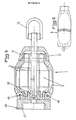
- la figure 3 est une vue de face, à une échelle différente, d'un premier mode de réalisation du module avant du dispositif conforme à l'invention ;
- la figure 4 est une vue de face, à une échelle différente, d'un premier mode de réalisation du module arrière du dispositif conforme à l'invention ;
- la figure 5 est une vue de face, à une échelle différente, d'un second mode de réalisation du module avant du dispositif conforme à l'invention dépourvu du moyen hydraulique ;
- la figure 6 est une vue de dessus d'un bras du module avant ou du module arrière du dispositif conforme à l'invention, et
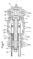
- la figure 7 est une vue de face, à une échelle différente, d'un second mode de réalisation du module arrière du dispositif conforme à l'invention.
- Conformément à l'invention, le dispositif de réhabilitation est caractérisé en ce que chaque module 1, 2 est pourvu de bras 3, 5 mobiles grâce à un moyen hydraulique 4, 6 relié à une pompe hydraulique 8, disposée en surface, d'une position hors service dans laquelle les bras 3, 5 définissent un diamètre nettement inférieur à celui de la canalisation 7 à réhabiliter, dans une position en service dans laquelle les bras 3, 5 définissent un diamètre égal ou très légèrement inférieur à celui de la canalisation 7 à réhabiliter, de manière à ce que le module avant 1, par pression des bras 3 sur les parois internes endommagées de la canalisation 7, joue le rôle d'écarteur et de guide afin de redonner à ladite canalisation 7 son diamètre initial et permettre le passage du module arrière 2 qui est, quant à lui, pourvu à chacune de ses deux extrémités de moyens d'étanchéité 9 délimitant avec la canalisation 7 une chambre 10 dans laquelle débouche au moins un tube 11 d'arrivée du produit colmatant, relié à une pompe 12 disposée en surface, par l'intermédiaire, par exemple, d'un flexible 30. Le flexible 30 pourra, par exemple, être fixé au tube 11 grâce à un accouplement rapide à cames connu sous la dénomination CAMLOCK.
- Le module avant 1 joue donc le rôle d'écarteur et de guide, permettant ainsi, comme le montre la figure 2 des dessins annexés, de dégager la canalisation 7 et de remettre en place les différents fragments de parois qui s'étaient soit détachés, soit effondrés dans celle-ci, et ce avant toute injection de produit colmatant. Toutes les alimentations s'effectuent par l'arrière du dispositif, que ce soient les alimentations des moyens hydrauliques 4, 6 ou l'alimentation en produit colmatant. Ainsi, ces alimentations, sous la forme de flexibles, ne peuvent pas être endommagées par des pans de parois de la canalisation 7 qui n'auraient pas encore été réparés.
- Le module avant 1 permet également une pénétration dans la canalisation 7, même lorsqu'il manque des morceaux de parois, la terre elle-même étant alors mise en place de manière à former une voûte.
- Selon un premier mode de réalisation de l'invention, les deux modules avant 1 et arrière 2 sont articulés entre eux, par exemple grâce à un système à cardan, à boule, à chaînes ou à câbles, de manière à per mettre un meilleur passage dans les canalisations 7, présentant souvent des variations angulaires et parfois même des coudes.
- Une telle articulation présente comme principal avantage d'éviter un éventuel blocage du dispositif dans la canalisation 7, qui serait dû à des variations angulaires de celle-ci (affaissement, coude, etc...).
- Les figures 3 et 4 des dessins annexés représentent les modules avant 1 et arrière 2 d'un dispositif de réhabilitation à chaînes. Comme on peut le voir sur ces deux figures, les deux modules avant 1 et arrière 2 sont démontables et sont reliés entre eux, par exemple grâce à un ensemble de raccords rapides hydrauliques 31 et de flexible hydraulique 32. Le flexible hydraulique 32 relie la tige centrale percée 19 du module 2 à l'axe primaire 20 du module 1.
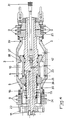
- Selon un second mode de réalisation de l'invention, et comme le montrent les figures 5 et 7 des dessins annexés, les deux modules avant 1 et arrière 2 sont démontables et sont reliés entre eux, par exemple par boulonnement 26 sur tube fileté 27.
- Selon une caractéristique supplémentaire de l'invention, et comme représenté aux revendications 3 et 5 des dessins annexés, le module avant 1 est pourvu d'un système d'accrochage 13 sous la forme d'un crochet, permettant de tracter le dispositif à l'intérieur de la canalisation 7 grâce à un câble de tirage 14 et un treuil 15 disposé en surface.
- Le treuil 15 peut être avantageusement à main.
- Le fait de pouvoir utiliser un treuil à main 15 résulte également de l'un des nombreux avantages du dispositif conforme à l'invention. En effet, le module avant 1 jouant le rôle d'écarteur, il s'ensuit que le dispositif ne nécessite qu'une puissance relativement faible pour progresser dans la canalisation 7. Un treuil à main 15 disposé en surface suffit, par conséquent, pour tracter l'ensemble du dispositif par l'intermédiaire du câble de tirage 14 (figure 1).
- Conformément à une autre caractéristique de l'invention, chaque moyen hydraulique 4, 6 est sous la forme d'un vérin pourvu d'un ressort de rappel 16, actionnant chaque bras 3, 5 en position de service contre une butée 17 par l'intermédiaire d'un système de segments coniques 33, 34 et 35, 36 coopérant entre elles, le vérin 4 par l'intermédiaire d'un flexible 18 relié, d'un côté, à la pompe hydraulique 8 et, de l'autre, à l'extrémité arrière de la tige centrale percée 19 du module 2, elle même reliée à l'axe primaire 20 du module 1, et le vérin 6 par l'intermédiaire d'un flexible 21 relié d'un côté à la pompe hydraulique 8 et, de l'autre, à l extrémité arrière de la tige percée 22 (figures 4 et 7).
- Cette disposition permet, par conséquent, comme déjà indiqué plus haut, des alimentations hydrauliques et en produit colmatant se faisant exclusivement par l'arrière du dispositif.
- Comme le montrent les figures 5 et 7 des dessins annexés, chaque bras 3, 5 est articulé autour de son extrémité opposée à celle en contact avec la butée 17 autour d'un axe d'articulation 40, 41.
- Comme représenté à la figure 4 des dessins annexés, l'axe d articulation 41 du module arrière 2 peut avantageusement être remplacé par un second système de segments coniques 37, 38 coopérant entre elles.
- Selon une caractéristique supplémentaire de l'invention, chaque bras 3, 5 est maintenu dans sa position initiale non écartée par un ressort de rappel 39.
- En outre, les bras 3, 5 sont munis de moyens de fixation de plaquettes 42, ces dernières permettant une adaptation du dispositif à différents diamètres de canalisation (voir figure 4 des dessins annexés).
- Comme représenté aux figures 3 à 5 et 7 des dessins annexés, les bras 5 du module arrière 2, ainsi que, le cas échéant, les plaquettes 42, sont avantageusement au nombre de six et sont munis de perforations 23 pour le passage du produit colmatant.
- Ces perforations 23 permettent ainsi au produit de passer de la chambre d'injection 10 dans les parois de la canalisation 7, non seulement entre les bras 5, mais aussi à travers ces mêmes bras 5, justement à travers les trous 23.
- Enfin, comme le montrent les figures 4 et 7 des dessins annexés, les moyens d'étanchéité 9 sont avantageusement sous la forme, à chacune des deux extrémités du module arrière 2, de trois joints en toile de caoutchouc en forme de disque maintenus en place par des rondelles 24 et des supports 25 et dimensionnés de telle façon qu'ils supportent la pression d'injection du produit colmatant dans la chambre d'injection 10 de l'ordre de 1 à 1,5 bar.
- On constate, par conséquent, qu'en ne remplaçant que les joints d'étanchéité 9 et les rondelles 24, et en fixant sur les bras 3, 5 des plaquettes 42 de l'épaisseur désirée, par exemple à l'aide de vis disposées dans des trous taraudés dont sont pourvus lesdits bras 3, 5, il est possible de réparer des canalisations 7 de diamètre différent (pouvant aller, comme déjà indiqué plus haut, de 150 à plus de 300 mm).
- Le dispositif conforme à l'invention, fonctionne, par conséquent, de la manière suivante :
- On commence par descendre à travers un regard 28 (figure 1) le module avant 1. Puis, on accroche le câble de tirage 14 au crochet 13 du module avant 1 et on actionne le treuil manuel 15 jusqu'à ce que le module avant 1 se trouve engagé dans la canalisation 7. Si celle-ci présente, dès le départ, des parties à réhabiliter, les bras 3 sont alors mis en pression par mise en route de la pompe 8 en surface (une dérivation dans les flexibles 18, 21 étant prévue) qui agit sur le vérin 4. Ils se plaquent contre les parois de la canalisation 7, ou de ce qu'il en reste,en s'écartant de quelques millimètres jusqu'à la butée 17 et la remettent à son diamètre initial, le terrain restant en place sous l'effet de voûte. Puis, la pompe 8 est à nouveau stoppée et le vérin 4 remet les bras 3 dans leur position initiale.
- Ensuite, on descend le module arrière 2 à travers le regard 28 et on le verrouille avec le module avant 1 (grâce au tube fileté 27 et aux boulons 26). On actionne alors le treuil 15 de manière à amener l'arrière du module 2 à l'entrée du regard 28. Les bras 3 sont ensuite à nouveau mis en pression pour remettre la partie de la canalisation 7 suivante à son diamètre initial. Simultanément ou ensuite, les bras 5 du module arrière 2 sont mis en pression par mise en route de la pompe 8 en surface qui agit sur le vérin 6. Ils se plaquent contre les parois de la canalisation 7 qui ont été préalablement remises en place, en s'écartant de quelques millimètres jusqu'à la butée 17, et la pompe 12 est mise en route de manière à injecter le produit colmatant dans la chambre d'injection 10, puis dans les parois elles-même. Cette injection s'effectue à une pression d'environ 1 à 1,5 bar. L'injection du produit colmatant se poursuit jusqu'à ce que la pression d'injection se stabilise, ceci indiquant que toutes les fissures ont été obstruées. Les pompes 8 et 12 sont alors stoppées.
- Après une courte attente de pré-durcissement de l'ordre d'une trentaine de secondes, le treuil 15 est à nouveau actionné manuellement de manière à avancer le dispositif conforme à l'invention dans la canalisation 7 d'une longueur légèrement inférieure à la chambre d'injection 10, ceci afin d'obtenir un recouvrement et d'éviter qu'une partie de la canalisation 7 n'ait pas été vérifiée et traitée.
- Puis, le module avant 1 entre à nouveau, le cas échéant, en action. Simultanément ou ensuite, le module arrière 2 entre également en action.
- Cette séquence d'étapes se poursuit jusqu'à ce que le dispositif ait parcouru l'ensemble du tronçon de la canalisation 7 à réhabiliter.
- On désolidarise alors les deux parties avant 1 et arrière 2 du dispositif et on les ressort à travers le regard 29.
- Il est à noter que la partie avant 1 peut également être utilisée seule lorsqu'il s'agit uniquement de débloquer et de nettoyer une canalisation 7 légèrement endommagée, sans pour autant qu'il soit nécessaire d'injecter du produit colmatant.
- Il faut également noter, par ailleurs, que le module arrière 2 peut être pourvu d'un second tube d'arrivée 11 de produit colmatant, les deux tubes 11 étant alors reliés au flexible 30, lorsqu'il est nécessaire d'injecter une grande quantité de ce produit.
- La description ci-dessus a, par conséquent, mis en valeur la grande efficacité du dispositif conforme à l'invention, ainsi que la facilité de sa mise en oeuvre et de son déplacement à l'intérieur d'une canalisation 7 à réhabiliter, ce, en particulier, grâce à la présence du module avant 1 qui joue le rôle d'écarteur et de guide, annulant ainsi tous les obstacles, tels qu'éclats dans la canalisation 7, et lui redonnant son diamètre initial, facilitant ainsi le passage du module arrière 2, ce qui permet une parfaite injection sur toute l'enveloppe de la canalisation 7, même là où celle-ci n'existe plus, le terrain étant alors utilisé comme coffrage extérieur.
- Bien entendu, l'invention n'est pas limitée au mode de réalisation décrit et représenté aux dessins annexés. Des modifications restent possibles, notamment du point de vue de la constitution des divers éléments ou par substitution d'équivalents techniques, sans sortir pour autant du domaine de protection de l'invention.
Claims (12)
Priority Applications (1)
| Application Number | Priority Date | Filing Date | Title |
|---|---|---|---|
| AT89440053T ATE76174T1 (de) | 1988-06-10 | 1989-06-08 | Vorrichtung zur renovierung vor ort von nichtbegehbaren rohrleitungen. |
Applications Claiming Priority (2)
| Application Number | Priority Date | Filing Date | Title |
|---|---|---|---|
| FR8807973A FR2632709B1 (fr) | 1988-06-10 | 1988-06-10 | Dispositif de rehabilitation in situ de canalisations non visitables de l'interieur |
| FR8807973 | 1988-06-10 |
Publications (2)
| Publication Number | Publication Date |
|---|---|
| EP0346256A1 true EP0346256A1 (fr) | 1989-12-13 |
| EP0346256B1 EP0346256B1 (fr) | 1992-05-13 |
Family
ID=9367291
Family Applications (1)
| Application Number | Title | Priority Date | Filing Date |
|---|---|---|---|
| EP89440053A Expired - Lifetime EP0346256B1 (fr) | 1988-06-10 | 1989-06-08 | Dispositif de réhabilitation in situ de canalisations non visitables de l'intérieur |
Country Status (14)
| Country | Link |
|---|---|
| US (1) | US4955755A (fr) |
| EP (1) | EP0346256B1 (fr) |
| JP (1) | JPH0235297A (fr) |
| AT (1) | ATE76174T1 (fr) |
| AU (1) | AU622675B2 (fr) |
| CA (1) | CA1312457C (fr) |
| DE (2) | DE346256T1 (fr) |
| DK (1) | DK283389A (fr) |
| ES (1) | ES2033125T3 (fr) |
| FR (1) | FR2632709B1 (fr) |
| GR (1) | GR3005285T3 (fr) |
| NO (1) | NO892388L (fr) |
| NZ (1) | NZ229466A (fr) |
| ZA (1) | ZA894396B (fr) |
Cited By (2)
| Publication number | Priority date | Publication date | Assignee | Title |
|---|---|---|---|---|
| FR2656913A1 (fr) * | 1990-01-05 | 1991-07-12 | Frey Andre | Dispositif de rehabilitation in situ de canalisations et de conduits non visitables de l'interieur et munis, notamment d'un regard unique. |
| FR2852661A1 (fr) | 2003-03-18 | 2004-09-24 | Andre Frey | Dispositif de rehabilitation in situ de canalisations non visitables |
Families Citing this family (12)
| Publication number | Priority date | Publication date | Assignee | Title |
|---|---|---|---|---|
| GB2249603B (en) * | 1990-11-02 | 1995-05-10 | British Gas Plc | Replacing mains |
| SE467171B (sv) * | 1991-01-17 | 1992-06-01 | Henrik Persson | Verktyg och foerfarande foer foernyelse av markfoerlagda roerledningar |
| FR2688292B1 (fr) * | 1992-03-06 | 1995-07-13 | Frey Andre | Dispositif de reparation in situ de conduits ou de canalisations non visitables et procede de rehabilitation mettant en óoeuvre ledit dispositif. |
| US6102118A (en) * | 1998-12-30 | 2000-08-15 | Moore; Curt A. | Multi-purpose adjustable centralizer system with tool |
| WO2003014613A1 (fr) * | 2001-08-07 | 2003-02-20 | Novaliner Technologies Inc. | Dispositif et procede pour la rehabilitation de conduits |
| US7497000B1 (en) * | 2004-10-22 | 2009-03-03 | At&T Corp. | Method for repairing a collapsed duct section |
| GB0803297D0 (en) | 2008-02-22 | 2008-04-02 | Htc Man Services Linited | Method and apparatus for lining a conduit |
| EP2998100A1 (fr) | 2010-05-13 | 2016-03-23 | Structural Group, Inc. | Systeme et procede de reparation et de renforcement de tuyau avec renforcement de traction interne enroule de façon helicoïdale |
| GB201418974D0 (en) | 2014-10-24 | 2014-12-10 | Kobus Services Ltd | Winch |
| GB201609000D0 (en) * | 2016-05-23 | 2016-07-06 | Kobus Services Ltd | Improved component for replacing pipes and method of use |
| CN115031085B (zh) * | 2022-05-30 | 2023-06-23 | 安徽省皖能新奥天然气有限公司 | 一种具备预警和防破坏的地下管网保护系统 |
| US12060963B1 (en) * | 2023-04-19 | 2024-08-13 | Danny Warren Consulting, LLC. | Method and system for encapsulating in-ground asbestos concrete pipe |
Citations (6)
| Publication number | Priority date | Publication date | Assignee | Title |
|---|---|---|---|---|
| FR1398057A (fr) * | 1964-03-25 | 1965-05-07 | Appareil pour le chemisage de conduits | |
| US4377984A (en) * | 1981-03-13 | 1983-03-29 | Spiniello Construction Company | Connecting assembly for pipe lining equipment |
| US4429720A (en) * | 1982-09-23 | 1984-02-07 | Beck Richard D | Apparatus for seeking out and repairing leaks in pipes |
| EP0146331A1 (fr) * | 1983-12-16 | 1985-06-26 | I.P.D. Systems Limited | Dispositif et méthode pour écarter des irrégularités dans ou pour l'élargissement de conduits souterrains |
| FR2579294A1 (fr) * | 1985-03-21 | 1986-09-26 | Socea Balency | Dispositif pour la refection in situ de canalisations, en particulier d'egouts, non visitables |
| WO1987003353A1 (fr) * | 1985-11-25 | 1987-06-04 | Entreprenadaktiebolaget E. & G. Jönsson | Procede de remise en etat de conduites souterraines |
Family Cites Families (6)
| Publication number | Priority date | Publication date | Assignee | Title |
|---|---|---|---|---|
| US2851061A (en) * | 1957-12-26 | 1958-09-09 | Louis A Bernard | Device for sealing sewer pipe lines |
| GB990622A (en) * | 1964-04-16 | 1965-04-28 | Penetryn System | Sleeve packer for chemical grouting |
| IL33199A (en) * | 1968-11-04 | 1972-10-29 | Mills D | Pipe relining method and apparatus |
| JPS5676792A (en) * | 1979-11-22 | 1981-06-24 | Kankyo Kaihatsu Kk | Reinforcing and repairing device of burried pipe like as gas pipe |
| WO1986000528A1 (fr) * | 1984-07-05 | 1986-01-30 | Genex Corporation | Gene clone et son procede de preparation et d'utilisation |
| GB8612654D0 (en) * | 1986-05-23 | 1986-07-02 | Ipd Systems Ltd | Correcting irregularities in/enlarging underground duct |
-
1988
- 1988-06-10 FR FR8807973A patent/FR2632709B1/fr not_active Expired - Lifetime
-
1989
- 1989-06-08 NZ NZ229466A patent/NZ229466A/xx unknown
- 1989-06-08 ES ES198989440053T patent/ES2033125T3/es not_active Expired - Lifetime
- 1989-06-08 EP EP89440053A patent/EP0346256B1/fr not_active Expired - Lifetime
- 1989-06-08 DE DE198989440053T patent/DE346256T1/de active Pending
- 1989-06-08 DE DE8989440053T patent/DE68901496D1/de not_active Expired - Lifetime
- 1989-06-08 AT AT89440053T patent/ATE76174T1/de not_active IP Right Cessation
- 1989-06-09 US US07/364,821 patent/US4955755A/en not_active Expired - Fee Related
- 1989-06-09 NO NO89892388A patent/NO892388L/no unknown
- 1989-06-09 DK DK283389A patent/DK283389A/da not_active Application Discontinuation
- 1989-06-09 JP JP1145504A patent/JPH0235297A/ja active Pending
- 1989-06-09 ZA ZA894396A patent/ZA894396B/xx unknown
- 1989-06-09 AU AU36273/89A patent/AU622675B2/en not_active Ceased
- 1989-06-12 CA CA000602496A patent/CA1312457C/fr not_active Expired - Fee Related
-
1992
- 1992-07-29 GR GR920401615T patent/GR3005285T3/el unknown
Patent Citations (6)
| Publication number | Priority date | Publication date | Assignee | Title |
|---|---|---|---|---|
| FR1398057A (fr) * | 1964-03-25 | 1965-05-07 | Appareil pour le chemisage de conduits | |
| US4377984A (en) * | 1981-03-13 | 1983-03-29 | Spiniello Construction Company | Connecting assembly for pipe lining equipment |
| US4429720A (en) * | 1982-09-23 | 1984-02-07 | Beck Richard D | Apparatus for seeking out and repairing leaks in pipes |
| EP0146331A1 (fr) * | 1983-12-16 | 1985-06-26 | I.P.D. Systems Limited | Dispositif et méthode pour écarter des irrégularités dans ou pour l'élargissement de conduits souterrains |
| FR2579294A1 (fr) * | 1985-03-21 | 1986-09-26 | Socea Balency | Dispositif pour la refection in situ de canalisations, en particulier d'egouts, non visitables |
| WO1987003353A1 (fr) * | 1985-11-25 | 1987-06-04 | Entreprenadaktiebolaget E. & G. Jönsson | Procede de remise en etat de conduites souterraines |
Cited By (2)
| Publication number | Priority date | Publication date | Assignee | Title |
|---|---|---|---|---|
| FR2656913A1 (fr) * | 1990-01-05 | 1991-07-12 | Frey Andre | Dispositif de rehabilitation in situ de canalisations et de conduits non visitables de l'interieur et munis, notamment d'un regard unique. |
| FR2852661A1 (fr) | 2003-03-18 | 2004-09-24 | Andre Frey | Dispositif de rehabilitation in situ de canalisations non visitables |
Also Published As
| Publication number | Publication date |
|---|---|
| DE68901496D1 (de) | 1992-06-17 |
| EP0346256B1 (fr) | 1992-05-13 |
| ZA894396B (en) | 1991-02-27 |
| NO892388L (no) | 1989-12-11 |
| GR3005285T3 (fr) | 1993-05-24 |
| JPH0235297A (ja) | 1990-02-05 |
| CA1312457C (fr) | 1993-01-12 |
| NO892388D0 (no) | 1989-06-09 |
| DK283389D0 (da) | 1989-06-09 |
| AU622675B2 (en) | 1992-04-16 |
| US4955755A (en) | 1990-09-11 |
| DE346256T1 (de) | 1990-05-23 |
| ATE76174T1 (de) | 1992-05-15 |
| ES2033125T3 (es) | 1993-03-01 |
| NZ229466A (en) | 1990-10-26 |
| FR2632709A1 (fr) | 1989-12-15 |
| AU3627389A (en) | 1989-12-14 |
| DK283389A (da) | 1989-12-11 |
| FR2632709B1 (fr) | 1990-08-31 |
Similar Documents
| Publication | Publication Date | Title |
|---|---|---|
| EP0346256B1 (fr) | Dispositif de réhabilitation in situ de canalisations non visitables de l'intérieur | |
| EP0559592B1 (fr) | Dispositif de réparation in situ de conduits ou de canalisations non visitables et procédé de réhabilitation mettant en oeuvre ledit dispositif | |
| FR2557669A1 (fr) | Procede de reparation de canalisations souterraines, notamment de gaz | |
| FR2470328A1 (fr) | Appareil pour renforcer et reparer une conduite | |
| WO2014006211A1 (fr) | Dispositif sanitaire pour animaux domestiques | |
| FR2658438A1 (fr) | Dispositif de desobstruction pour canalisation, systeme contenant un tel dispositif et procede de desobstruction d'une canalisation a l'aide d'un tel systeme. | |
| FR2680380A1 (fr) | Procede pour realiser un corps de fondation universel et dispositif pour mettre en óoeuvre ce procede. | |
| FR3068122B1 (fr) | Installation de nettoyage d'echangeur thermique et systeme associe | |
| EP0762030B1 (fr) | Appareil de poussée d'une conduite en matière plastique pour tuber intérieurement une canalisation métallique à rénover | |
| FR2579294A1 (fr) | Dispositif pour la refection in situ de canalisations, en particulier d'egouts, non visitables | |
| FR2602568A1 (fr) | Dispositif de guidage et de protection pour la pose de canalisations | |
| FR2812463A1 (fr) | Dispositif de pose dans une conduite par air comprime d'un filin muni d'un furet | |
| FR2499880A1 (fr) | Equipage de decapage des parois des egouts visitables et conduits analogues | |
| FR3078692A1 (fr) | Dispositif formant un devidoir d’une pluralite de tuyaux flexibles a derouler et connecter successivement les uns aux autres, procedes de fonctionnement associes | |
| FR2812709A1 (fr) | Procede et dispositif pour obturer une canalisation secondaire de derivation | |
| FR2523617A1 (fr) | Installation de vidange, notamment pour sanitaires d'avion | |
| EP3657061B1 (fr) | Procede de pose d'un organe hydraulique et installation | |
| EP0582531B1 (fr) | Procédé de test d'étanchéité d'une canalisation ou d'un réseau de canalisations ainsi qu'une installation permettant la mise en oeuvre de ce procédé | |
| FR2732380A1 (fr) | Procede et dispositif pour maintenir en service un drainage d'evacuation pendant une construction de canalisation | |
| FR2961721A1 (fr) | Dispositif de nettoyage de machine agricole. | |
| FR3085366A1 (fr) | Dévidoir multi-bobines, pour tuyau incendie souple, qui intègre une motopompe et dont au moins l’une des bobines présente un tambour qui est à diamètre variable. | |
| FR2752877A1 (fr) | Procede par demi-bouclier et dispositif de mise en oeuvre de celui-ci | |
| CA1117864A (fr) | Dispositif de colmatage rapide des fuites de petrole des puits sous pression | |
| FR2656913A1 (fr) | Dispositif de rehabilitation in situ de canalisations et de conduits non visitables de l'interieur et munis, notamment d'un regard unique. | |
| FR2961575A1 (fr) | Dispositif et procede de rehabilitation d'une canalisation |
Legal Events
| Date | Code | Title | Description |
|---|---|---|---|
| PUAI | Public reference made under article 153(3) epc to a published international application that has entered the european phase |
Free format text: ORIGINAL CODE: 0009012 |
|
| AK | Designated contracting states |
Kind code of ref document: A1 Designated state(s): AT BE CH DE ES FR GB GR IT LI LU NL SE |
|
| 17P | Request for examination filed |
Effective date: 19900122 |
|
| DET | De: translation of patent claims | ||
| 17Q | First examination report despatched |
Effective date: 19910129 |
|
| GRAA | (expected) grant |
Free format text: ORIGINAL CODE: 0009210 |
|
| AK | Designated contracting states |
Kind code of ref document: B1 Designated state(s): AT BE CH DE ES FR GB GR IT LI LU NL SE |
|
| REF | Corresponds to: |
Ref document number: 76174 Country of ref document: AT Date of ref document: 19920515 Kind code of ref document: T |
|
| REF | Corresponds to: |
Ref document number: 68901496 Country of ref document: DE Date of ref document: 19920617 |
|
| GBT | Gb: translation of ep patent filed (gb section 77(6)(a)/1977) | ||
| ITF | It: translation for a ep patent filed | ||
| REG | Reference to a national code |
Ref country code: GR Ref legal event code: FG4A Free format text: 3005285 |
|
| REG | Reference to a national code |
Ref country code: ES Ref legal event code: FG2A Ref document number: 2033125 Country of ref document: ES Kind code of ref document: T3 |
|
| PLBE | No opposition filed within time limit |
Free format text: ORIGINAL CODE: 0009261 |
|
| STAA | Information on the status of an ep patent application or granted ep patent |
Free format text: STATUS: NO OPPOSITION FILED WITHIN TIME LIMIT |
|
| 26N | No opposition filed | ||
| PGFP | Annual fee paid to national office [announced via postgrant information from national office to epo] |
Ref country code: GB Payment date: 19940601 Year of fee payment: 6 |
|
| PGFP | Annual fee paid to national office [announced via postgrant information from national office to epo] |
Ref country code: AT Payment date: 19940615 Year of fee payment: 6 |
|
| PGFP | Annual fee paid to national office [announced via postgrant information from national office to epo] |
Ref country code: SE Payment date: 19940617 Year of fee payment: 6 |
|
| PGFP | Annual fee paid to national office [announced via postgrant information from national office to epo] |
Ref country code: ES Payment date: 19940622 Year of fee payment: 6 |
|
| PGFP | Annual fee paid to national office [announced via postgrant information from national office to epo] |
Ref country code: NL Payment date: 19940630 Year of fee payment: 6 Ref country code: GR Payment date: 19940630 Year of fee payment: 6 Ref country code: BE Payment date: 19940630 Year of fee payment: 6 |
|
| PGFP | Annual fee paid to national office [announced via postgrant information from national office to epo] |
Ref country code: LU Payment date: 19940731 Year of fee payment: 6 |
|
| EPTA | Lu: last paid annual fee | ||
| EAL | Se: european patent in force in sweden |
Ref document number: 89440053.0 |
|
| PG25 | Lapsed in a contracting state [announced via postgrant information from national office to epo] |
Ref country code: LU Free format text: LAPSE BECAUSE OF NON-PAYMENT OF DUE FEES Effective date: 19950608 Ref country code: GB Effective date: 19950608 Ref country code: AT Effective date: 19950608 |
|
| PG25 | Lapsed in a contracting state [announced via postgrant information from national office to epo] |
Ref country code: SE Effective date: 19950609 Ref country code: ES Free format text: LAPSE BECAUSE OF THE APPLICANT RENOUNCES Effective date: 19950609 |
|
| PG25 | Lapsed in a contracting state [announced via postgrant information from national office to epo] |
Ref country code: BE Effective date: 19950630 |
|
| BERE | Be: lapsed |
Owner name: FREY ANDRE Effective date: 19950630 |
|
| PG25 | Lapsed in a contracting state [announced via postgrant information from national office to epo] |
Ref country code: GR Free format text: THE PATENT HAS BEEN ANNULLED BY A DECISION OF A NATIONAL AUTHORITY Effective date: 19951231 |
|
| PG25 | Lapsed in a contracting state [announced via postgrant information from national office to epo] |
Ref country code: NL Effective date: 19960101 |
|
| GBPC | Gb: european patent ceased through non-payment of renewal fee |
Effective date: 19950608 |
|
| REG | Reference to a national code |
Ref country code: GR Ref legal event code: MM2A Free format text: 3005285 |
|
| NLV4 | Nl: lapsed or anulled due to non-payment of the annual fee |
Effective date: 19960101 |
|
| EUG | Se: european patent has lapsed |
Ref document number: 89440053.0 |
|
| PGFP | Annual fee paid to national office [announced via postgrant information from national office to epo] |
Ref country code: CH Payment date: 19971001 Year of fee payment: 9 |
|
| PG25 | Lapsed in a contracting state [announced via postgrant information from national office to epo] |
Ref country code: LI Free format text: LAPSE BECAUSE OF NON-PAYMENT OF DUE FEES Effective date: 19980630 Ref country code: CH Free format text: LAPSE BECAUSE OF NON-PAYMENT OF DUE FEES Effective date: 19980630 |
|
| REG | Reference to a national code |
Ref country code: CH Ref legal event code: PL |
|
| PGFP | Annual fee paid to national office [announced via postgrant information from national office to epo] |
Ref country code: FR Payment date: 19990621 Year of fee payment: 11 |
|
| REG | Reference to a national code |
Ref country code: ES Ref legal event code: FD2A Effective date: 19991007 |
|
| PGFP | Annual fee paid to national office [announced via postgrant information from national office to epo] |
Ref country code: DE Payment date: 20000628 Year of fee payment: 12 |
|
| PG25 | Lapsed in a contracting state [announced via postgrant information from national office to epo] |
Ref country code: FR Free format text: LAPSE BECAUSE OF NON-PAYMENT OF DUE FEES Effective date: 20010228 |
|
| REG | Reference to a national code |
Ref country code: FR Ref legal event code: ST |
|
| PG25 | Lapsed in a contracting state [announced via postgrant information from national office to epo] |
Ref country code: DE Free format text: LAPSE BECAUSE OF NON-PAYMENT OF DUE FEES Effective date: 20020403 |
|
| PG25 | Lapsed in a contracting state [announced via postgrant information from national office to epo] |
Ref country code: IT Free format text: LAPSE BECAUSE OF NON-PAYMENT OF DUE FEES;WARNING: LAPSES OF ITALIAN PATENTS WITH EFFECTIVE DATE BEFORE 2007 MAY HAVE OCCURRED AT ANY TIME BEFORE 2007. THE CORRECT EFFECTIVE DATE MAY BE DIFFERENT FROM THE ONE RECORDED. Effective date: 20050608 |