EP0346258A2 - Giessverschluss zur linearen und symmetrie-axialen Verstellung - Google Patents
Giessverschluss zur linearen und symmetrie-axialen Verstellung Download PDFInfo
- Publication number
- EP0346258A2 EP0346258A2 EP89470007A EP89470007A EP0346258A2 EP 0346258 A2 EP0346258 A2 EP 0346258A2 EP 89470007 A EP89470007 A EP 89470007A EP 89470007 A EP89470007 A EP 89470007A EP 0346258 A2 EP0346258 A2 EP 0346258A2
- Authority
- EP
- European Patent Office
- Prior art keywords
- nozzle
- refractory
- parts
- plate
- insert
- Prior art date
- Legal status (The legal status is an assumption and is not a legal conclusion. Google has not performed a legal analysis and makes no representation as to the accuracy of the status listed.)
- Granted
Links
Images



Classifications
-
- B—PERFORMING OPERATIONS; TRANSPORTING
- B22—CASTING; POWDER METALLURGY
- B22D—CASTING OF METALS; CASTING OF OTHER SUBSTANCES BY THE SAME PROCESSES OR DEVICES
- B22D41/00—Casting melt-holding vessels, e.g. ladles, tundishes, cups or the like
- B22D41/08—Casting melt-holding vessels, e.g. ladles, tundishes, cups or the like for bottom pouring
-
- B—PERFORMING OPERATIONS; TRANSPORTING
- B22—CASTING; POWDER METALLURGY
- B22D—CASTING OF METALS; CASTING OF OTHER SUBSTANCES BY THE SAME PROCESSES OR DEVICES
- B22D41/00—Casting melt-holding vessels, e.g. ladles, tundishes, cups or the like
- B22D41/14—Closures
- B22D41/22—Closures sliding-gate type, i.e. having a fixed plate and a movable plate in sliding contact with each other for selective registry of their openings
- B22D41/26—Closures sliding-gate type, i.e. having a fixed plate and a movable plate in sliding contact with each other for selective registry of their openings characterised by a rotatively movable plate
-
- B—PERFORMING OPERATIONS; TRANSPORTING
- B22—CASTING; POWDER METALLURGY
- B22D—CASTING OF METALS; CASTING OF OTHER SUBSTANCES BY THE SAME PROCESSES OR DEVICES
- B22D41/00—Casting melt-holding vessels, e.g. ladles, tundishes, cups or the like
- B22D41/14—Closures
- B22D41/22—Closures sliding-gate type, i.e. having a fixed plate and a movable plate in sliding contact with each other for selective registry of their openings
- B22D41/40—Means for pressing the plates together
Definitions
- the present invention relates to the casting of aggressive or high temperature liquids, in particular liquid metals such as steel.
- the greater or lesser coincidence of the orifices makes it possible to adjust the flow rate.
- the relative movement of the plates can be linear, or even rotary: - In the first case, the orifice (s) of the movable plate move along a straight line. - In the second case, the orifice (s) of the movable plate move in a circle.
- the irruption of the metal causes in the refractory plates a sudden thermal shock, which causes harmful cracking in several respects, in particular: - they make it more or less random to reuse them for subsequent emptying. - They can be the source of untimely aspirations of gas, in particular ambient air, by the fast flowing metal flow.
- the plates must be made of suitable materials: high content of alumina, magnesia, zirconia, etc., particularly sensitive to shocks thermal.
- the object of the present invention is to avoid as far as possible these cracks and this premature wear of the plates.
- the starting point of the thermal shock is in the pouring orifice, where a jet of liquid metal passes at high temperature, in particular if it is steel.
- the heat then diffuses towards the periphery of the plate.
- the thickness of the plate, or closing element also plays a role, since the first face is in contact with the other plate, or element, and the second is oriented, either towards the container, or towards the ambient.
- the tendency to break or crack is greater or less depending on the nature of the refractory material, the physical properties of which, such as thermal expansion, thermal conductivity, etc., vary significantly.
- the invention therefore retains as perfect symmetry as possible of all the elements subjected to thermal shocks and to corrosion caused by the flow of the fluid, in particular liquid steel.
- the main movable plate moves along a straight line or any curve passing through its axis, common to the plate and to its hole. To simplify the rest of the presentation, we will consider the simpler case of rectilinear movement.
- the rotation of the plates can be controlled by any mechanical, hydraulic or electrical process known to those skilled in the art.
- the same source of movement is used for the displacement of the movable plate or its pivoting.
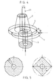
- the plates or elements are produced in two or more parts: for example a central wear part made of particularly noble material (ceramic with high melting point, metallic ceramic, etc.), surrounded by a less noble and less expensive support material (alumina, magnesia, etc.)
- particularly noble material ceramic with high melting point, metallic ceramic, etc.
- a less noble and less expensive support material alumina, magnesia, etc.
- the cylindrical wear distribution technique makes it possible to minimize the size of the central insert, depending on the requirements dictated by the diameter of the hole, the resistance to thermal shocks and to physical and chemical attacks by the fluid. sunk.
- the fixed and movable plates are frequently surrounded by a thick metal banding, hot crimped, intended to protect them against possible disintegration during their dismantling.
- This strapping can advantageously be constituted by a ceramic ring having an adequate elasticity or by a metal ring with shape memory.
- the refractory surround of the insert can serve both as a support and as a hoop, if it is chosen from a suitable material.
- This strapping can be provided with a device preventing any rotation of the movable plate relative to the slide during the pivoting operations during casting.
- the central insert of the movable obturator element is one piece with the lower collecting nozzle.
- the upper surface of the insert / nozzle duly rectified, then constitutes the central element of wear of the mobile shutter: it is integral with the latter by a conical fitting.
- the tapered joint is filled with an adhesive or an adequate refractory grout with quick setting, ensuring the tightness and mechanical consistency of the assembly.
- the sliding assembly can be disassembled, in order to exchange the insert / nozzle, for a new use.
- the insert / nozzle is a "consumable" element, that is to say that after disassembly, its worn upper part is again rectified using a special machine so as to allow a new assembly and a new use.
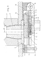
- the pressure of application of the plates one on the other must ensure sealing and maintain sufficient flexibility to the assembly, and in particular absorb the expansions of the refractory parts: it is exerted by the lower fixed part of the system, called in general "cover".
- This cover is reinforced for example by ribs or side members at the place where it exerts its pressure on the moving assembly.
- balls can be used to ensure the sliding of the slide against the cover.
- the balls are made of ceramic material, as well as the bearing surfaces or they circulate (side members and slide): they can even rest on the rectified underside of the movable plate itself.
- the balls are replaced by smooth bearings made of suitably treated metal, or of ceramic.
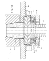
- the collecting nozzle, integral with the movable plate is connected to the latter by a refractory seal (grout or dry refractory felt): the nozzle is held against the movable plate by its support.
- a refractory seal grout or dry refractory felt
- the cover no longer exerts its pressure on the slide but on the nozzle, by means of its support.
- a threaded nozzle holder is used; the rotation of the support causes the nozzle to rise and pushes the movable plate upwards against the fixed plate, the reaction forces being absorbed by the cover.
- the tightening of the nozzle can be carried out using a conventional torque wrench.
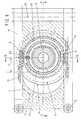
- the tightening can be carried out effortlessly using the endless screws, racks or drive gears of the sliding assembly: it suffices for this purpose to immobilize the nozzle support at the using a wedge secured to the chassis or the cover, and to rotate the slide in the appropriate direction as if one were carrying out an azimuth operation of the movable plate.
- the shim is replaced by a torque limiting blocking device: in this way, when the tightening of the plates reaches a certain predetermined value, the blocking in rotation of the nozzle is eliminated, and it can again rotate freely, integral with the assembly of the slide.
- the dynamometric blocking device can then be removed, to avoid thermal stresses from the casting of the metal.
- the movable plate inside the slide must keep a small possibility of vertical movement, parallel to itself, to allow clamping by the nozzle, but it must not be able to turn in order to avoid any loosening during use.
- the plate is left free to rotate in its housing at the same time as the nozzle to avoid any sliding at the joint; in this case it is also possible to use an insert / nozzle, as described below. The assembly is then locked against any new rotation during use.
- this type of tightening is adapted to the case of a device with 3 plates: in fact the collecting nozzle remaining immobile in the axis of the fixed plate, the tightening forces do not move.
- the movable plate and the collecting nozzle are pre-assembled or cast in one piece, and form a monobloc assembly.
- the collecting nozzle is positioned in a conventional manner by introducing it from the inside of the slide before putting the movable plate: this arrangement does not allow the independent mounting and dismounting of the nozzle.
- the worms can be controlled, for example, by two electric motors controlled and adjusted independently.
- Adequate cooling is provided to ensure proper operation of the assembly.
Landscapes
- Mechanical Engineering (AREA)
- Engineering & Computer Science (AREA)
- Casting Support Devices, Ladles, And Melt Control Thereby (AREA)
- Pens And Brushes (AREA)
- Insulators (AREA)
- Ignition Installations For Internal Combustion Engines (AREA)
- Surgical Instruments (AREA)
- Processing Of Solid Wastes (AREA)
- Extrusion Moulding Of Plastics Or The Like (AREA)
- Vehicle Body Suspensions (AREA)
- Table Devices Or Equipment (AREA)
- Containers And Packaging Bodies Having A Special Means To Remove Contents (AREA)
- Continuous Casting (AREA)
Priority Applications (1)
| Application Number | Priority Date | Filing Date | Title |
|---|---|---|---|
| AT89470007T ATE86158T1 (de) | 1988-05-13 | 1989-04-10 | Giessverschluss zur linearen und symmetrieaxialen verstellung. |
Applications Claiming Priority (2)
| Application Number | Priority Date | Filing Date | Title |
|---|---|---|---|
| FR8806617A FR2631266B1 (fr) | 1988-05-13 | 1988-05-13 | Obturateur de coulee a deplacement lineaire et symetrie axiale |
| FR8806617 | 1988-05-13 |
Publications (3)
| Publication Number | Publication Date |
|---|---|
| EP0346258A2 true EP0346258A2 (de) | 1989-12-13 |
| EP0346258A3 EP0346258A3 (en) | 1990-01-31 |
| EP0346258B1 EP0346258B1 (de) | 1993-03-03 |
Family
ID=9366385
Family Applications (1)
| Application Number | Title | Priority Date | Filing Date |
|---|---|---|---|
| EP89470007A Revoked EP0346258B1 (de) | 1988-05-13 | 1989-04-10 | Giessverschluss zur linearen und symmetrie-axialen Verstellung |
Country Status (11)
| Country | Link |
|---|---|
| US (1) | US5186845A (de) |
| EP (1) | EP0346258B1 (de) |
| JP (1) | JPH02504241A (de) |
| KR (1) | KR970005413B1 (de) |
| AT (1) | ATE86158T1 (de) |
| BR (1) | BR8906963A (de) |
| DE (1) | DE68905086T2 (de) |
| ES (1) | ES2039923T3 (de) |
| FR (1) | FR2631266B1 (de) |
| WO (1) | WO1989010812A1 (de) |
| ZA (1) | ZA893553B (de) |
Cited By (4)
| Publication number | Priority date | Publication date | Assignee | Title |
|---|---|---|---|---|
| US5076476A (en) * | 1988-06-09 | 1991-12-31 | Societe Belge Des Produits Refractaires | Method for controlling a flow rate in a valve and a valve for the application of said method |
| DE4231692C1 (de) * | 1992-09-22 | 1994-03-24 | Dolomitwerke Gmbh | Drehverschluß für metallurgische Gefäße |
| BE1008119A3 (fr) * | 1994-03-21 | 1996-01-23 | Szadkowski Stanislav | Dispositif de regulation de debit a fermeture coulissante d'un recipient metallurgique. |
| WO2006094846A1 (en) * | 2005-03-10 | 2006-09-14 | Tech-Gate S.A. | A linear sliding gate valve for a metallurgical vessel |
Families Citing this family (3)
| Publication number | Priority date | Publication date | Assignee | Title |
|---|---|---|---|---|
| US6168053B1 (en) * | 1999-06-21 | 2001-01-02 | Consarc Corporation | Positioning apparatus and method for precision pouring of a liquid from a vessel |
| DE10324801A1 (de) * | 2003-06-02 | 2005-01-05 | Knöllinger FLO-TEC GmbH | Gießpfannenschieber |
| CN103551547B (zh) * | 2013-11-08 | 2015-10-14 | 镇江市电站辅机厂有限公司 | 多路定量阀 |
Family Cites Families (12)
| Publication number | Priority date | Publication date | Assignee | Title |
|---|---|---|---|---|
| LU37533A1 (de) * | 1959-06-15 | |||
| US3764042A (en) * | 1972-08-03 | 1973-10-09 | United States Steel Corp | Reciprocable slidable gate with rotating slide element |
| US3841539A (en) * | 1973-03-01 | 1974-10-15 | United States Steel Corp | Collector nozzle for slidable gates |
| JPS5477237A (en) * | 1977-11-28 | 1979-06-20 | Shinagawa Refractories Co | Fannshaped multiihole slideespray brick and sliding nozzle apparatus |
| GB1595815A (en) * | 1978-03-21 | 1981-08-19 | Vesuvius Int Corp | Flow control device for molten metal |
| CA1126472A (en) * | 1978-06-19 | 1982-06-29 | Flo-Con Systems, Inc. | Rotary valve |
| CH659872A5 (de) * | 1983-09-02 | 1987-02-27 | Stopinc Ag | Verschlussplatte fuer einen schiebeverschluss. |
| DE3423157C1 (de) * | 1984-06-22 | 1985-06-20 | Metacon AG, Zürich | Feuerfestes Plattenpaar fuer schwenk- bzw. drehbewegliche Schiebeverschluesse |
| JPS61159259A (ja) * | 1984-12-28 | 1986-07-18 | Toshiba Ceramics Co Ltd | 溶融金属排出装置 |
| JPS61159261A (ja) * | 1984-12-28 | 1986-07-18 | Toshiba Ceramics Co Ltd | 溶融金属排出装置 |
| CA1279189C (en) * | 1985-11-18 | 1991-01-22 | Tetsuya Yoshihara | Rotary nozzle system |
| CH675976A5 (de) * | 1988-01-15 | 1990-11-30 | Stopinc Ag |
-
1988
- 1988-05-13 FR FR8806617A patent/FR2631266B1/fr not_active Expired - Lifetime
-
1989
- 1989-04-10 WO PCT/FR1989/000163 patent/WO1989010812A1/fr not_active Ceased
- 1989-04-10 JP JP1505287A patent/JPH02504241A/ja active Pending
- 1989-04-10 BR BR898906963A patent/BR8906963A/pt not_active IP Right Cessation
- 1989-04-10 DE DE8989470007T patent/DE68905086T2/de not_active Expired - Fee Related
- 1989-04-10 EP EP89470007A patent/EP0346258B1/de not_active Revoked
- 1989-04-10 KR KR1019900700062A patent/KR970005413B1/ko not_active Expired - Lifetime
- 1989-04-10 ES ES198989470007T patent/ES2039923T3/es not_active Expired - Lifetime
- 1989-04-10 US US07/465,093 patent/US5186845A/en not_active Expired - Fee Related
- 1989-04-10 AT AT89470007T patent/ATE86158T1/de not_active IP Right Cessation
- 1989-05-13 ZA ZA893553A patent/ZA893553B/xx unknown
Cited By (10)
| Publication number | Priority date | Publication date | Assignee | Title |
|---|---|---|---|---|
| US5076476A (en) * | 1988-06-09 | 1991-12-31 | Societe Belge Des Produits Refractaires | Method for controlling a flow rate in a valve and a valve for the application of said method |
| DE4231692C1 (de) * | 1992-09-22 | 1994-03-24 | Dolomitwerke Gmbh | Drehverschluß für metallurgische Gefäße |
| BE1008119A3 (fr) * | 1994-03-21 | 1996-01-23 | Szadkowski Stanislav | Dispositif de regulation de debit a fermeture coulissante d'un recipient metallurgique. |
| WO2006094846A1 (en) * | 2005-03-10 | 2006-09-14 | Tech-Gate S.A. | A linear sliding gate valve for a metallurgical vessel |
| EP1707291A1 (de) | 2005-03-10 | 2006-10-04 | Tech-Gate S.A. | Schiebeverschluss |
| EP1900459A2 (de) | 2005-03-10 | 2008-03-19 | Tech-Gate S.A. | Linearer Schieberverschluss für ein metallurgisches Gefäß |
| EA010251B1 (ru) * | 2005-03-10 | 2008-06-30 | Тех-Гате С.А. | Линейно скользящий шиберный затвор для металлургической ёмкости |
| US7648053B2 (en) | 2005-03-10 | 2010-01-19 | Tech-Gate S.A. | Linear sliding gate valve for a metallurgical vessel |
| EA013176B1 (ru) * | 2005-03-10 | 2010-02-26 | Тех-Гате С.А. | Линейно скользящий шиберный затвор для металлургической емкости |
| AU2006222134B2 (en) * | 2005-03-10 | 2010-05-20 | Tech-Gate S.A. | A linear sliding gate valve for a metallurgical vessel |
Also Published As
| Publication number | Publication date |
|---|---|
| WO1989010812A1 (fr) | 1989-11-16 |
| EP0346258A3 (en) | 1990-01-31 |
| FR2631266B1 (fr) | 1990-09-14 |
| US5186845A (en) | 1993-02-16 |
| DE68905086T2 (de) | 1993-08-05 |
| DE68905086D1 (de) | 1993-04-08 |
| FR2631266A1 (fr) | 1989-11-17 |
| KR900701441A (ko) | 1990-12-03 |
| ATE86158T1 (de) | 1993-03-15 |
| KR970005413B1 (ko) | 1997-04-16 |
| ES2039923T3 (es) | 1993-10-01 |
| EP0346258B1 (de) | 1993-03-03 |
| BR8906963A (pt) | 1990-12-11 |
| ZA893553B (en) | 1990-01-31 |
| JPH02504241A (ja) | 1990-12-06 |
Similar Documents
| Publication | Publication Date | Title |
|---|---|---|
| LU85957A1 (fr) | Plaque refractaire et buse de coulee,et procede de montage de plaques refractaires dans une vanne coulissante | |
| EP0346258B1 (de) | Giessverschluss zur linearen und symmetrie-axialen Verstellung | |
| EP0115724B1 (de) | Spannvorrichtung insbesondere zum Spannen von Werkstücken auf einer Werkzeugmaschine | |
| BE1001330A3 (fr) | Plaque de fermeture en matiere refractaire et fermeture a glissement pour busette de coulee d'un recipient contenant du metal en fusion. | |
| EP0269180A2 (de) | Vorrichtung zum Giessen eines pastenartigen Metalles | |
| EP1439016A1 (de) | Giessrohr, Spannvorrichtung für Giessrohr und Giessvorrichtung | |
| EP3193072A1 (de) | Universalschutzvorrichtung für gasflasche | |
| EP0894556A1 (de) | Seitenwand für eine Zweirollenstranggiessanlage zur Herstellung von dünnen Metallbändern | |
| FR2745211A1 (fr) | Repartiteur equipe d'un changeur de tube et plaque pour le changeur de tube | |
| EP0194990B1 (de) | Vorrichtung zum Festklemmen eines Verschleisselementes für den Schieberverschluss eines metallurgischen Behälters | |
| EP0432073A1 (de) | Einrichtung zum Stranggiessen von dünnen metallischen Produkten zwischen zwei Walzen | |
| FR2569591A1 (fr) | Plaque refractaire pour obturateurs coulissants de recipients metallurgiques | |
| CA2134286C (fr) | Cylindre de coulee d'une installation de coulee continue sur un ou entre deux cylindres | |
| EP0767714B1 (de) | Seitenwand für eine stranggiessvorrichtung zum giessen von dünnblechen | |
| FR2674950A1 (fr) | Mortier a barillet. | |
| FR2883632A1 (fr) | Four circulaire en deux parties et systemes de liaison destines a des fours circulaires | |
| CA1258170A (fr) | Poches de coulee pour metal en fusion | |
| FR2695335A1 (fr) | Tiroir linéaire de poche à acier. | |
| EP1133372B1 (de) | Kippbarer behälter zur behandlung von metallschmelze und dichtverbindung mit einer feststehenden rinne | |
| FR2613646A1 (fr) | Dispositif d'obturation laterale pour lingotiere de coulee continue entre cylindres | |
| EP1101086B1 (de) | Messvorrichtung des wärmeaustauschs in wechselndem, nicht stationären oder übergangs-betrieb | |
| FR2695580A1 (fr) | Dispositif de coulée continue entre cylindres de produits métalliques minces. | |
| CA2032065A1 (fr) | Dispositif de coulee continue de produits metalliques minces entre deux cylindres refroidis en rotation | |
| BE1004078A3 (fr) | Dispositif antivortex adaptable aux trous de coulees de poches de coulee. | |
| FR2944542A1 (fr) | Etai de soutien. |
Legal Events
| Date | Code | Title | Description |
|---|---|---|---|
| PUAI | Public reference made under article 153(3) epc to a published international application that has entered the european phase |
Free format text: ORIGINAL CODE: 0009012 |
|
| AK | Designated contracting states |
Kind code of ref document: A2 Designated state(s): AT BE CH DE ES GB GR IT LI LU NL SE |
|
| PUAL | Search report despatched |
Free format text: ORIGINAL CODE: 0009013 |
|
| AK | Designated contracting states |
Kind code of ref document: A3 Designated state(s): AT BE CH DE ES GB GR IT LI LU NL SE |
|
| 17P | Request for examination filed |
Effective date: 19900611 |
|
| 17Q | First examination report despatched |
Effective date: 19911016 |
|
| GRAA | (expected) grant |
Free format text: ORIGINAL CODE: 0009210 |
|
| AK | Designated contracting states |
Kind code of ref document: B1 Designated state(s): AT BE CH DE ES GB GR IT LI LU NL SE |
|
| REF | Corresponds to: |
Ref document number: 86158 Country of ref document: AT Date of ref document: 19930315 Kind code of ref document: T |
|
| REF | Corresponds to: |
Ref document number: 68905086 Country of ref document: DE Date of ref document: 19930408 |
|
| ITF | It: translation for a ep patent filed | ||
| GBT | Gb: translation of ep patent filed (gb section 77(6)(a)/1977) |
Effective date: 19930611 |
|
| REG | Reference to a national code |
Ref country code: GR Ref legal event code: FG4A Free format text: 3008070 |
|
| REG | Reference to a national code |
Ref country code: ES Ref legal event code: FG2A Ref document number: 2039923 Country of ref document: ES Kind code of ref document: T3 |
|
| PLBI | Opposition filed |
Free format text: ORIGINAL CODE: 0009260 |
|
| 26 | Opposition filed |
Opponent name: VESUVIUS FRANCE S.A. Effective date: 19931123 |
|
| NLR1 | Nl: opposition has been filed with the epo |
Opponent name: VESUVIUS FRANCE S.A. |
|
| EPTA | Lu: last paid annual fee | ||
| EAL | Se: european patent in force in sweden |
Ref document number: 89470007.9 |
|
| PGFP | Annual fee paid to national office [announced via postgrant information from national office to epo] |
Ref country code: GB Payment date: 19950331 Year of fee payment: 7 |
|
| PGFP | Annual fee paid to national office [announced via postgrant information from national office to epo] |
Ref country code: AT Payment date: 19950412 Year of fee payment: 7 |
|
| PGFP | Annual fee paid to national office [announced via postgrant information from national office to epo] |
Ref country code: CH Payment date: 19950413 Year of fee payment: 7 |
|
| PGFP | Annual fee paid to national office [announced via postgrant information from national office to epo] |
Ref country code: SE Payment date: 19950419 Year of fee payment: 7 Ref country code: DE Payment date: 19950419 Year of fee payment: 7 |
|
| PGFP | Annual fee paid to national office [announced via postgrant information from national office to epo] |
Ref country code: ES Payment date: 19950426 Year of fee payment: 7 |
|
| PGFP | Annual fee paid to national office [announced via postgrant information from national office to epo] |
Ref country code: GR Payment date: 19950428 Year of fee payment: 7 |
|
| PGFP | Annual fee paid to national office [announced via postgrant information from national office to epo] |
Ref country code: NL Payment date: 19950430 Year of fee payment: 7 |
|
| PGFP | Annual fee paid to national office [announced via postgrant information from national office to epo] |
Ref country code: LU Payment date: 19950601 Year of fee payment: 7 |
|
| PGFP | Annual fee paid to national office [announced via postgrant information from national office to epo] |
Ref country code: BE Payment date: 19950602 Year of fee payment: 7 |
|
| PG25 | Lapsed in a contracting state [announced via postgrant information from national office to epo] |
Ref country code: LU Free format text: LAPSE BECAUSE OF NON-PAYMENT OF DUE FEES Effective date: 19960410 Ref country code: GB Effective date: 19960410 Ref country code: AT Effective date: 19960410 |
|
| PG25 | Lapsed in a contracting state [announced via postgrant information from national office to epo] |
Ref country code: SE Effective date: 19960411 Ref country code: ES Free format text: LAPSE BECAUSE OF NON-PAYMENT OF DUE FEES Effective date: 19960411 |
|
| PG25 | Lapsed in a contracting state [announced via postgrant information from national office to epo] |
Ref country code: LI Free format text: LAPSE BECAUSE OF NON-PAYMENT OF DUE FEES Effective date: 19960430 Ref country code: CH Free format text: LAPSE BECAUSE OF NON-PAYMENT OF DUE FEES Effective date: 19960430 Ref country code: BE Effective date: 19960430 |
|
| BERE | Be: lapsed |
Owner name: DETALLE EDOUARD Effective date: 19960430 |
|
| PG25 | Lapsed in a contracting state [announced via postgrant information from national office to epo] |
Ref country code: GR Free format text: THE PATENT HAS BEEN ANNULLED BY A DECISION OF A NATIONAL AUTHORITY Effective date: 19961031 |
|
| PG25 | Lapsed in a contracting state [announced via postgrant information from national office to epo] |
Ref country code: NL Effective date: 19961101 |
|
| GBPC | Gb: european patent ceased through non-payment of renewal fee |
Effective date: 19960410 |
|
| REG | Reference to a national code |
Ref country code: GR Ref legal event code: MM2A Free format text: 3008070 |
|
| REG | Reference to a national code |
Ref country code: CH Ref legal event code: PL |
|
| PG25 | Lapsed in a contracting state [announced via postgrant information from national office to epo] |
Ref country code: DE Effective date: 19970101 |
|
| NLV4 | Nl: lapsed or anulled due to non-payment of the annual fee |
Effective date: 19961101 |
|
| EUG | Se: european patent has lapsed |
Ref document number: 89470007.9 |
|
| RDAH | Patent revoked |
Free format text: ORIGINAL CODE: EPIDOS REVO |
|
| RDAG | Patent revoked |
Free format text: ORIGINAL CODE: 0009271 |
|
| STAA | Information on the status of an ep patent application or granted ep patent |
Free format text: STATUS: PATENT REVOKED |
|
| 27W | Patent revoked |
Effective date: 19980528 |
|
| PLAB | Opposition data, opponent's data or that of the opponent's representative modified |
Free format text: ORIGINAL CODE: 0009299OPPO |