EP0346404B1 - Procede pour determiner le contenu energetique d' accumulateurs electrochimiques - Google Patents
Procede pour determiner le contenu energetique d' accumulateurs electrochimiques Download PDFInfo
- Publication number
- EP0346404B1 EP0346404B1 EP88909078A EP88909078A EP0346404B1 EP 0346404 B1 EP0346404 B1 EP 0346404B1 EP 88909078 A EP88909078 A EP 88909078A EP 88909078 A EP88909078 A EP 88909078A EP 0346404 B1 EP0346404 B1 EP 0346404B1
- Authority
- EP
- European Patent Office
- Prior art keywords
- energy content
- eiw
- content value
- terminal voltage
- energy
- Prior art date
- Legal status (The legal status is an assumption and is not a legal conclusion. Google has not performed a legal analysis and makes no representation as to the accuracy of the status listed.)
- Expired - Lifetime
Links
Images


Classifications
-
- H—ELECTRICITY
- H01—ELECTRIC ELEMENTS
- H01M—PROCESSES OR MEANS, e.g. BATTERIES, FOR THE DIRECT CONVERSION OF CHEMICAL ENERGY INTO ELECTRICAL ENERGY
- H01M10/00—Secondary cells; Manufacture thereof
- H01M10/42—Methods or arrangements for servicing or maintenance of secondary cells or secondary half-cells
- H01M10/48—Accumulators combined with arrangements for measuring, testing or indicating the condition of cells, e.g. the level or density of the electrolyte
-
- B—PERFORMING OPERATIONS; TRANSPORTING
- B60—VEHICLES IN GENERAL
- B60L—PROPULSION OF ELECTRICALLY-PROPELLED VEHICLES; SUPPLYING ELECTRIC POWER FOR AUXILIARY EQUIPMENT OF ELECTRICALLY-PROPELLED VEHICLES; ELECTRODYNAMIC BRAKE SYSTEMS FOR VEHICLES IN GENERAL; MAGNETIC SUSPENSION OR LEVITATION FOR VEHICLES; MONITORING OPERATING VARIABLES OF ELECTRICALLY-PROPELLED VEHICLES; ELECTRIC SAFETY DEVICES FOR ELECTRICALLY-PROPELLED VEHICLES
- B60L58/00—Methods or circuit arrangements for monitoring or controlling batteries or fuel cells, specially adapted for electric vehicles
- B60L58/10—Methods or circuit arrangements for monitoring or controlling batteries or fuel cells, specially adapted for electric vehicles for monitoring or controlling batteries
- B60L58/12—Methods or circuit arrangements for monitoring or controlling batteries or fuel cells, specially adapted for electric vehicles for monitoring or controlling batteries responding to state of charge [SoC]
-
- B—PERFORMING OPERATIONS; TRANSPORTING
- B60—VEHICLES IN GENERAL
- B60L—PROPULSION OF ELECTRICALLY-PROPELLED VEHICLES; SUPPLYING ELECTRIC POWER FOR AUXILIARY EQUIPMENT OF ELECTRICALLY-PROPELLED VEHICLES; ELECTRODYNAMIC BRAKE SYSTEMS FOR VEHICLES IN GENERAL; MAGNETIC SUSPENSION OR LEVITATION FOR VEHICLES; MONITORING OPERATING VARIABLES OF ELECTRICALLY-PROPELLED VEHICLES; ELECTRIC SAFETY DEVICES FOR ELECTRICALLY-PROPELLED VEHICLES
- B60L7/00—Electrodynamic brake systems for vehicles in general
-
- G—PHYSICS
- G01—MEASURING; TESTING
- G01R—MEASURING ELECTRIC VARIABLES; MEASURING MAGNETIC VARIABLES
- G01R31/00—Arrangements for testing electric properties; Arrangements for locating electric faults; Arrangements for electrical testing characterised by what is being tested not provided for elsewhere
- G01R31/36—Arrangements for testing, measuring or monitoring the electrical condition of accumulators or electric batteries, e.g. capacity or state of charge [SoC]
- G01R31/3644—Constructional arrangements
- G01R31/3646—Constructional arrangements for indicating electrical conditions or variables, e.g. visual or audible indicators
-
- G—PHYSICS
- G01—MEASURING; TESTING
- G01R—MEASURING ELECTRIC VARIABLES; MEASURING MAGNETIC VARIABLES
- G01R31/00—Arrangements for testing electric properties; Arrangements for locating electric faults; Arrangements for electrical testing characterised by what is being tested not provided for elsewhere
- G01R31/36—Arrangements for testing, measuring or monitoring the electrical condition of accumulators or electric batteries, e.g. capacity or state of charge [SoC]
- G01R31/382—Arrangements for monitoring battery or accumulator variables, e.g. SoC
- G01R31/3828—Arrangements for monitoring battery or accumulator variables, e.g. SoC using current integration
-
- B—PERFORMING OPERATIONS; TRANSPORTING
- B60—VEHICLES IN GENERAL
- B60L—PROPULSION OF ELECTRICALLY-PROPELLED VEHICLES; SUPPLYING ELECTRIC POWER FOR AUXILIARY EQUIPMENT OF ELECTRICALLY-PROPELLED VEHICLES; ELECTRODYNAMIC BRAKE SYSTEMS FOR VEHICLES IN GENERAL; MAGNETIC SUSPENSION OR LEVITATION FOR VEHICLES; MONITORING OPERATING VARIABLES OF ELECTRICALLY-PROPELLED VEHICLES; ELECTRIC SAFETY DEVICES FOR ELECTRICALLY-PROPELLED VEHICLES
- B60L2240/00—Control parameters of input or output; Target parameters
- B60L2240/40—Drive Train control parameters
- B60L2240/54—Drive Train control parameters related to batteries
- B60L2240/547—Voltage
-
- B—PERFORMING OPERATIONS; TRANSPORTING
- B60—VEHICLES IN GENERAL
- B60L—PROPULSION OF ELECTRICALLY-PROPELLED VEHICLES; SUPPLYING ELECTRIC POWER FOR AUXILIARY EQUIPMENT OF ELECTRICALLY-PROPELLED VEHICLES; ELECTRODYNAMIC BRAKE SYSTEMS FOR VEHICLES IN GENERAL; MAGNETIC SUSPENSION OR LEVITATION FOR VEHICLES; MONITORING OPERATING VARIABLES OF ELECTRICALLY-PROPELLED VEHICLES; ELECTRIC SAFETY DEVICES FOR ELECTRICALLY-PROPELLED VEHICLES
- B60L2240/00—Control parameters of input or output; Target parameters
- B60L2240/40—Drive Train control parameters
- B60L2240/54—Drive Train control parameters related to batteries
- B60L2240/549—Current
-
- Y—GENERAL TAGGING OF NEW TECHNOLOGICAL DEVELOPMENTS; GENERAL TAGGING OF CROSS-SECTIONAL TECHNOLOGIES SPANNING OVER SEVERAL SECTIONS OF THE IPC; TECHNICAL SUBJECTS COVERED BY FORMER USPC CROSS-REFERENCE ART COLLECTIONS [XRACs] AND DIGESTS
- Y02—TECHNOLOGIES OR APPLICATIONS FOR MITIGATION OR ADAPTATION AGAINST CLIMATE CHANGE
- Y02E—REDUCTION OF GREENHOUSE GAS [GHG] EMISSIONS, RELATED TO ENERGY GENERATION, TRANSMISSION OR DISTRIBUTION
- Y02E60/00—Enabling technologies; Technologies with a potential or indirect contribution to GHG emissions mitigation
- Y02E60/10—Energy storage using batteries
-
- Y—GENERAL TAGGING OF NEW TECHNOLOGICAL DEVELOPMENTS; GENERAL TAGGING OF CROSS-SECTIONAL TECHNOLOGIES SPANNING OVER SEVERAL SECTIONS OF THE IPC; TECHNICAL SUBJECTS COVERED BY FORMER USPC CROSS-REFERENCE ART COLLECTIONS [XRACs] AND DIGESTS
- Y02—TECHNOLOGIES OR APPLICATIONS FOR MITIGATION OR ADAPTATION AGAINST CLIMATE CHANGE
- Y02T—CLIMATE CHANGE MITIGATION TECHNOLOGIES RELATED TO TRANSPORTATION
- Y02T10/00—Road transport of goods or passengers
- Y02T10/60—Other road transportation technologies with climate change mitigation effect
- Y02T10/70—Energy storage systems for electromobility, e.g. batteries
Definitions
- the invention relates to a method for determining the energy content of electrochemical energy stores, having the features according to the first part of patent claim 1.
- Such energy stores serve, both as individual cells and in the form of a battery, with any number of interconnected cells, in a variety of ways as traction and starter batteries for land, air and water vehicles, as well as the energy supply for a variety of portable and stationary Systems, of machine and device controls, of measuring devices, signal and warning systems and for solar-electric operated storage.
- WO 86/00418 describes a method for monitoring the state of charge of rechargeable batteries, in particular nickel-cadmium accumulators, a reference value corresponding to a specific state of charge being stored there, the terminal voltage, the current strength and the time during each charging and discharging cycle of the battery, measured and converted into a quantity corresponding to the supplied or consumed amount of energy, taking into account the direction of the current, from which, based on the reference value, the actual state of charge values are calculated and the rate of change of the terminal voltage in the charging and discharging cycle is monitored is and wherein after passing through a phase of relatively uniform and low voltage change rate, at least one point in time is determined at which a characteristic stronger voltage change rate occurs and the calculated actual charge state value for this, or a defined delay siege time is adjusted to the predetermined reference value.
- a device with arrangements for measuring the terminal voltage of the battery, the direction and amplitude of the charging or discharging current and the battery temperature, as well as a program-controlled arithmetic unit, which is connected to the measuring arrangements and controlled so that it monitors the rate of change of the terminal voltage during all charging and discharging cycles of the battery and determines an actual state of charge value when the rate of change in voltage undergoes a greater change after a substantially constant phase.
- a memory is also required there, which is connected to the computing unit for storing reference values and the actual values of the supplied or consumed amounts of energy developed in the computing unit.
- an interface and driver circuit for coupling the computing unit with peripheral input and output devices are necessary.
- This method also has the disadvantage of interfering in the circuit of the battery system, especially since the current determined there on a measuring shunt, only when the battery is sufficiently constant, allows a calculation together with other reaction values.
- a test method for direct current sources such as accumulators, batteries, or the like, is known, in which one measures the AC internal resistance of the direct current source to be tested as a parameter for its condition.
- the Open-circuit voltage of the direct current source measured and by pairing the measured values of the open-circuit voltage on the one hand and the internal resistance on the other, in mutually assigned characteristic functional links of the open circuit voltage as a function of the ampere-hour capacity, or of the AC internal resistance as a function of the ampere-hour capacity for different physical states of a direct current source of the same type as the test object, a separate statement about the state of charge on the one hand and the physical state on the other hand.
- a technically relatively complex electronic test device in particular with a complicated resistance measuring device, for determining the internal AC resistance of a direct current source, as well as a constant current generator with a constant frequency of 100 Hz and a selective voltage amplifier, which is matched to the frequency of the constant current generator, are required.
- the invention has for its object to provide a method of the type mentioned, for determining the energy content of electrochemical energy stores, which should only work with a measurement of the terminal voltage of an energy store and knowledge of the discharge characteristic of the energy store to be measured. It should be ensured that the energy content value of a measured electrochemical energy storage device is displayed in percent, or in a power unit, or in a distance, or in a time unit, or a work cycle.
- the advantage of this new method and the device for implementing this method is not only that there is no need to intervene in the load circuit of an energy store to be measured, that the accuracy of the energy content determined is independent of the load on an energy store, that the age and expresses the ambient temperature of an energy store in the value of the measured terminal voltage and fully takes into account in the determined energy content value that the energy content value still available and / or the remaining discharge time can be displayed there in advance, in particular on the assumption that the average load on the energy store will not change significantly since the beginning of the discharge, but also that the, essentially simple, technical equipment expenditure in the most economical case and with sufficient accuracy consists only of a voltage-measuring instrument can, which is equipped with a special scale, the division of the measuring range is determined by the respective reference values.
- Another advantage is the simple acquisition of the reference values from the respectively measured terminal voltage and the relative energy content value, based on the static discharge characteristics corresponding to the different discharge currents, which are stored in a computer and from which the determined function value corresponding to the relative energy content value, by interpolation individual reference values, is calculated and to which the measured terminal voltage relates when determining the energy content value.
- a specially developed computer program using Neville's algorithm for determining the function value from the individual reference values is also advantageous here.
- this assumed discharge current aEl can be calculated together with the reference values BW corresponding to the current relative energy content value EIW from the field of the characteristic curves 2, and the measured terminal voltage U KL , by interpolation of the individual reference values BW, so that so that the energy content value EIW of an energy store can be determined.
- This determined energy content value EIW expresses how much electrical energy, in percent, has already been used in the energy store, or how much energy is still available.
- the determination of the energy content value EIW always begins with a 100% residual energy content value, based on a specific operating voltage range of the energy store.
- FIG. 2 shows a function diagram with the terminal voltage U KL as a function of the discharge time in (sec, min, h) for different discharge currents.
- the terminal voltage U KL is again plotted on the ordinate axis and the discharge time on the abscissa axis.
- the discharge characteristics 2 there represent the nominal state of an energy store. Function diagrams, according to the
- Fig. 2 are issued by the manufacturers of chemical energy storage.
- the abscissa axis is inverted, ie 100% - K.
- Determining or calculating an energy content value always begins with a remaining capacity of 100%. Depending on the state of charge of an energy store, at the beginning of the discharge, 100% residual capacity can mean different capacities or energy content values EIW.
- This residual capacity or the residual energy content value EIW, in percent, and the terminal voltage U KL determine a reference value BW in the field of the characteristic curves 2, which corresponds to an assumed discharge current EI. In almost all cases, this current does not match the measurable real discharge current EI.
- the available maximum energy content value EIW, or the maximum capacity K in the energy storage device 1 is dependent on the load.
- the nominal capacity can only be taken when the nominal current is loaded.
- the achievable degree of discharge which is equal to one (1) at nominal load, drops to values of 0.2 with larger discharge currents. This is due to a blocking effect due to the slow diffusion rate of the electrolyte.
- the concentrated electrolyte between the plates of the energy store cannot diffuse into the pores of the plates quickly enough. Acid depletion occurs in the pores of the plates. As a result, the electrolyte resistance rises sharply, the terminal voltage breaks down and there is an early end of discharge.
- the program for calculating the energy content value EIW therefore knows the maximum capacitance values for different discharge currents EI, for example the nine (9) data sheet characteristics 2 from FIG. 2.
- the discharge current EI of the characteristic curves 2 multiplied by the maximum achievable discharge time T results in the maximum capacity K max .
- the correct point in time is calculated when no more charge may be removed in order to avoid deep discharges.
- the influencing variables such as aging, the electrolyte temperature and the degree of charging, are expressed in the size of the terminal voltage U KL and thus also in the calculated function value FW.
- FIG. Any function value FW can lie there on the surface shown.
- BW indicates the reference values there, EIW the axis for the energy content value, in percent.
- U KL the function axis for the terminal voltage.
- 6 shows a simple circuit with an energy store 1 and a consumer 6.
- 4 denotes an instrument for the immediate determination of the energy content value EIW by measuring the terminal voltage U KL at the terminals 7 of the energy store 1.
- a device for determining the energy content value EIW can consist of a voltage-measuring instrument 4, in particular a pointer instrument, which, as shown in FIG. 8, can be equipped with a scale 3 which is provided with several areas 8 which can correspond to different discharge currents EI or corresponding reference values BW / function values FW.
- the respective discharge current EI on which the measurement is based, or reference value BW, or function value FW, can be signaled there by an optical signal 9.
- the individual measuring ranges 8 can be preselected manually mechanically or automatically electronically, as can be seen from FIG. 9.
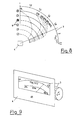
- the 10 shows a measuring device for an electric vehicle with an analog display device on a, in percent, calibrated scale 3, on which the percentage residual capacity K can be read.
- the time 11 and / or the operating hours 12 and / or the cycle time 13 can also be displayed in this measuring device.
- Additional displays 14 for cell, outside and engine temperature can be provided.
- Such measuring devices can be useful in electric vehicles in general, in particular in electrically powered forklifts.
- the advertisements can be made in digital form.
- the entire device-side scale 3.1 can in particular be an LCD display module.
- 11 shows a block diagram of an electronic, computer-controlled device for determining the energy content value EIW.
- 1 denotes an energy store with a load 6 in the circuit.
- 15 identifies the electronic part of the device, with a power supply 16, for supplying the device with an analog-to-digital converter 17, for processing the measured terminal voltage U KL , the information of which is supplied to the central unit CPU via a data bus 19, which on the Command register with the stored reference values BW of at least three characteristic curves 2, inform of individual reference values EBW, is used in the calculation of the energy content value EIW.
- the calculated values are stored in RAM, in percent, in a time unit, in work cycles, or in a power unit.
- Input / output devices 21 such as a keyboard for data input, a magnetic card reader for data input, an optoelectronic reader for data input, a printer for data output, or a coordinate recorder for data output, can be connected via an interface 20.
- 20 display devices 22 can be connected to this interface for the immediate display of output and / or input values.
- optical and / or acoustic signal transmitters 23 can be connected there, which emit a signal in particular in the case of an energy content value EIW of zero (0) in the energy store 1.
- the electronic device is not limited to the hardware shown and described there, but can be expanded as required, with regard to the read-only memory ROM, as well as the read-write memory RAM.
- the individual reference values EBW of the static characteristic curves 2 from the data sheet, according to FIG. 2 are stored in the memory ROM in one or more rectangular matrices, and that the columns stored there contain the energy content value EIW, in particular in percent , and the stored lines correspond to the individual reference values EBW of characteristic curve 2.
- the individual reference values EBW can be calculated in any number for the formation of a functional value FW for the specific determination of the energy content value EIW.
- the present method and the devices mentioned are suitable not only for determining the energy content value EIW of electrochemical, rechargeable or non-rechargeable energy stores, but also for determining the energy content value of static energy stores, such as capacitors for storing an electrical charge.
Landscapes
- Engineering & Computer Science (AREA)
- Power Engineering (AREA)
- General Physics & Mathematics (AREA)
- Physics & Mathematics (AREA)
- Mechanical Engineering (AREA)
- Transportation (AREA)
- Electrochemistry (AREA)
- General Chemical & Material Sciences (AREA)
- Chemical Kinetics & Catalysis (AREA)
- Chemical & Material Sciences (AREA)
- Manufacturing & Machinery (AREA)
- Life Sciences & Earth Sciences (AREA)
- Sustainable Development (AREA)
- Sustainable Energy (AREA)
- Secondary Cells (AREA)
- Tests Of Electric Status Of Batteries (AREA)
- Charge And Discharge Circuits For Batteries Or The Like (AREA)
Abstract
Claims (1)
Applications Claiming Priority (3)
| Application Number | Priority Date | Filing Date | Title |
|---|---|---|---|
| DE3736481A DE3736481C2 (de) | 1987-10-28 | 1987-10-28 | Verfahren und Einrichtung zur Ermittlung des Energieinhaltswertes von elektrochemischen Energiespeichern |
| DE3736481 | 1987-10-28 | ||
| PCT/DE1988/000647 WO1989004000A1 (fr) | 1987-10-28 | 1988-10-22 | Procede et dispositif pour determiner le contenu energetique d'accumulateurs electrochimiques |
Publications (3)
| Publication Number | Publication Date |
|---|---|
| EP0346404A1 EP0346404A1 (fr) | 1989-12-20 |
| EP0346404B1 true EP0346404B1 (fr) | 1993-08-11 |
| EP0346404B2 EP0346404B2 (fr) | 1999-07-14 |
Family
ID=6339251
Family Applications (1)
| Application Number | Title | Priority Date | Filing Date |
|---|---|---|---|
| EP88909078A Expired - Lifetime EP0346404B2 (fr) | 1987-10-28 | 1988-10-22 | Procede pour determiner le contenu energetique d' accumulateurs electrochimiques |
Country Status (5)
| Country | Link |
|---|---|
| US (1) | US5151865A (fr) |
| EP (1) | EP0346404B2 (fr) |
| JP (1) | JPH02501952A (fr) |
| DE (1) | DE3736481C2 (fr) |
| WO (1) | WO1989004000A1 (fr) |
Families Citing this family (43)
| Publication number | Priority date | Publication date | Assignee | Title |
|---|---|---|---|---|
| DE3808559C2 (de) * | 1988-03-15 | 1994-04-21 | Hella Kg Hueck & Co | Verfahren und Vorrichtung zur Überwachung der Leistungsgrenze einer Starterbatterie |
| DE3910868A1 (de) * | 1989-04-04 | 1990-12-13 | Jungheinrich Kg | Verfahren zur ermittlung des jeweiligen ladezustandes einer bleibatterie und einrichtung zur durchfuehrung des verfahrens |
| DE3910904A1 (de) * | 1989-04-04 | 1990-10-11 | Elektron Bremen | Verfahren zur ueberwachung des ladezustandes einer wiederaufladbaren, verschlossenen batterie |
| WO1990013823A1 (fr) * | 1989-05-12 | 1990-11-15 | Fraunhofer-Gesellschaft zur Förderung der angewandten Forschung e.V. | Procede et dispositif pour determiner des variables physiques concernant des accumulateurs d'energie electriques rechargeables |
| EP0432690B1 (fr) * | 1989-12-11 | 1996-03-13 | Canon Kabushiki Kaisha | Chargeur |
| JPH04334874A (ja) * | 1991-05-13 | 1992-11-20 | Sony Corp | 電池式受信機 |
| JPH0583805A (ja) * | 1991-09-17 | 1993-04-02 | Honda Motor Co Ltd | 電気自動車の電気負荷制限装置 |
| DE4221894C1 (de) * | 1992-07-03 | 1993-10-28 | Benning Elektrotechnik | Verfahren zur Ermittlung des aktuellen Ladezustandes einer Traktionsbatterie eines Flurförderfahrzeuges |
| US5315287A (en) * | 1993-01-13 | 1994-05-24 | David Sol | Energy monitoring system for recreational vehicles and marine vessels |
| WO1994017425A1 (fr) * | 1993-01-27 | 1994-08-04 | Seiko Epson Corporation | Instrument de mesure de capacite pour batterie |
| US5331684A (en) * | 1993-02-17 | 1994-07-26 | Itt Corporation | Helmet mounting for night vision assembly |
| DE4402716C2 (de) * | 1994-01-29 | 1996-08-29 | Ibm | Abschätzung der Lebensdauer und der Kapazität eines Energiespeichers |
| US5583413A (en) * | 1994-09-06 | 1996-12-10 | Cruising Equipment, Inc. | Power conversion equipment monitor/controller method and apparatus |
| JPH08136626A (ja) * | 1994-09-16 | 1996-05-31 | Seiko Epson Corp | バッテリー残存容量計及びバッテリー残存容量の演算方法 |
| US5659465A (en) * | 1994-09-23 | 1997-08-19 | Aeroviroment, Inc. | Peak electrical power conversion system |
| US5631540A (en) * | 1994-11-23 | 1997-05-20 | Lucent Technologies Inc. | Method and apparatus for predicting the remaining capacity and reserve time of a battery on discharge |
| DE29504159U1 (de) * | 1995-03-10 | 1995-06-22 | Alfred Härtl Elektronik-Entwicklungen, 92242 Hirschau | Gerät zum Behandeln von wiederaufladbaren Batterien |
| FR2734061B1 (fr) * | 1995-05-12 | 1997-06-20 | Thomson Csf | Procede de determination de la charge disponible d'une batterie d'accumulateurs en fin de decharge |
| JPH0933623A (ja) * | 1995-07-19 | 1997-02-07 | Nissan Motor Co Ltd | バッテリー容量計 |
| FR2740877B1 (fr) * | 1995-11-06 | 1998-01-09 | Renault | Procede pour determiner l'etat de charge d'une batterie d'accumulateurs |
| US5656919A (en) * | 1995-11-14 | 1997-08-12 | Cruising Equipment, Inc. | Accurate battery state-of-charge monitoring and indicating apparatus and method |
| US6081104A (en) * | 1998-11-20 | 2000-06-27 | Applied Power Corporation | Method and apparatus for providing energy to a lighting system |
| DE19960761C1 (de) * | 1999-12-16 | 2001-05-23 | Daimler Chrysler Ag | Verfahren zur Überwachung der Restladung und der Leistungsfähigkeit einer Batterie |
| ES2186585B1 (es) * | 2001-10-23 | 2004-01-01 | Trama Tecnoambiental S L | Procedimiento y dispositivo para garantizar el suministro de energia en instalaciones autonomas |
| DE102005026583A1 (de) * | 2005-06-09 | 2006-12-28 | Hella Kgaa Hueck & Co. | Batteriezustandsanzeigesystem für eine Kraftfahrzeugbatterie |
| CA2737243A1 (fr) * | 2007-09-20 | 2009-03-26 | Better Place GmbH | Reseau de vehicule electrique |
| PL2198474T3 (pl) | 2007-10-10 | 2012-12-31 | Commissariat Energie Atomique | Sposób oceny stanu naładowania akumulatora ołowiowo-kwasowego |
| US7993155B2 (en) | 2008-09-19 | 2011-08-09 | Better Place GmbH | System for electrically connecting batteries to electric vehicles |
| US8006793B2 (en) | 2008-09-19 | 2011-08-30 | Better Place GmbH | Electric vehicle battery system |
| US8118147B2 (en) | 2009-09-11 | 2012-02-21 | Better Place GmbH | Cable dispensing system |
| US7972167B2 (en) * | 2009-09-14 | 2011-07-05 | Better Place GmbH | Electrical connector with a flexible blade-shaped housing with a handle with an opening |
| DE102010020993A1 (de) * | 2010-05-19 | 2011-11-24 | Li-Tec Battery Gmbh | Verfahren zum Steuern der maximalen Laderate einer elektrochemischen Energiespeichereinrichtung |
| US8035341B2 (en) * | 2010-07-12 | 2011-10-11 | Better Place GmbH | Staged deployment for electrical charge spots |
| FR2991105B1 (fr) * | 2012-05-24 | 2016-12-09 | Commissariat Energie Atomique | Procede de determination d'un etat d'energie d'un accumulateur electrochimique, dispositif, support et programme informatique |
| FR2991076B1 (fr) * | 2012-05-24 | 2015-03-13 | Commissariat Energie Atomique | Procede de traitement d'un ensemble de quadruplets de valeurs relatifs a des points de fonctionnement d'un accumulateur electrochimique, procede de determination d'un etat d'energie a partir des donnees issues du procede de traitement, support d'enregistrement, programme informatique et dispositif |
| TWI629827B (zh) * | 2012-07-09 | 2018-07-11 | 飛奈吉有限公司 | 用於控制金屬空氣電池組之操作之系統及方法 |
| FR3000623B1 (fr) | 2012-12-28 | 2018-04-27 | Sunna Design | Procede de pilotage dynamique d'un equipement electrique |
| US20140210399A1 (en) | 2013-01-25 | 2014-07-31 | Pylon Aviation Services Llc | Portable electric power source for aircraft |
| USD820204S1 (en) | 2013-01-25 | 2018-06-12 | Aviation Battery Systems Llc | Portable ground power unit |
| DE102018212545A1 (de) * | 2018-07-27 | 2020-01-30 | Audi Ag | Verfahren zum Überwachen eines Zustands einer Batterie, Überwachungseinrichtung und Kraftfahrzeug |
| CN109878378A (zh) * | 2019-01-30 | 2019-06-14 | 北京长城华冠汽车科技股份有限公司 | 电池内阻计算方法、装置及电池管理系统 |
| US11704749B2 (en) * | 2019-11-25 | 2023-07-18 | Itron Global Sarl | Networked utility services and vehicle charging stations |
| US20220200295A1 (en) * | 2020-12-23 | 2022-06-23 | Medtronic, Inc. | Systems and method for charging batteries |
Family Cites Families (20)
| Publication number | Priority date | Publication date | Assignee | Title |
|---|---|---|---|---|
| CH607344A5 (fr) * | 1977-01-21 | 1978-12-15 | Etic Electronic Time Co | |
| US4180770A (en) * | 1978-03-01 | 1979-12-25 | Anderson Power Products, Inc. | Method and apparatus for determining the capacity of lead acid storage batteries |
| DE2926716C2 (de) * | 1979-07-03 | 1982-02-04 | Robert Bosch Gmbh, 7000 Stuttgart | Prüfverfahren für Gleichstromquellen, wie Akkumulatoren, Batterien o.dgl., und Prüfgerät |
| DE3018981A1 (de) * | 1980-05-17 | 1981-11-26 | Accumulatorenfabriken Wilhelm Hagen Ag Soest-Kassel-Berlin, 4770 Soest | Verfahren zum kontinuierlichen messen und anzeigen des ladezustandes eines akkumulators |
| DE3031890C2 (de) * | 1980-06-28 | 1987-02-05 | Lucas Industries Ltd., Birmingham, West Midlands | Verfahren zum Laden einer Akkumulatorbatterie |
| US4388618A (en) * | 1981-01-07 | 1983-06-14 | Curtis Instruments, Inc. | Battery state of charge indicator operating on bidirectional integrations of terminal voltage |
| DE3116371A1 (de) * | 1981-04-21 | 1983-02-17 | Gottfried Hagen AG, 5000 Köln | Verfahren zum feststellen des entladezustandes eines elektrischen akkumulators und schaltungsanordnung zum durchfuehren dieses verfahrens |
| FR2523728A1 (fr) * | 1982-03-17 | 1983-09-23 | Renault | Procede et dispositif de mesure de l'etat de charge d'un generateur electrochimique en fonctionnement |
| DE3216412A1 (de) * | 1982-05-03 | 1983-11-03 | Varta Batterie Ag, 3000 Hannover | Verfahren zur ermittlung des ladezustandes von elektrischen akkumulatoren |
| US4737702A (en) * | 1982-06-07 | 1988-04-12 | Norand Corporation | Battery charging control system particularly for hand held device |
| US4709202A (en) * | 1982-06-07 | 1987-11-24 | Norand Corporation | Battery powered system |
| US4455523A (en) * | 1982-06-07 | 1984-06-19 | Norand Corporation | Portable battery powered system |
| US4553081A (en) * | 1982-06-07 | 1985-11-12 | Norand Corporation | Portable battery powered system |
| US4558281A (en) * | 1982-06-12 | 1985-12-10 | Lucas Industries | Battery state of charge evaluator |
| US4575679A (en) * | 1983-05-10 | 1986-03-11 | General Electric Co. | Automatic load shed control for spacecraft power system |
| DE3407409C2 (de) * | 1984-02-29 | 1986-12-11 | Robert Bosch Gmbh, 7000 Stuttgart | Prüfverfahren für Gleichstromquellen, wie Akkumulatoren oder Batterien und Prüfgerät zur Durchführung des Prüfverfahrens |
| JPS61502564A (ja) * | 1984-06-30 | 1986-11-06 | コプマン,ウド | 再充電可能なバッテリの充電状態をモニタする方法および装置 |
| US4633418A (en) * | 1984-07-11 | 1986-12-30 | The United States Of America As Represented By The Secretary Of The Air Force | Battery control and fault detection method |
| JPS61170678A (ja) * | 1985-01-25 | 1986-08-01 | Nissan Motor Co Ltd | バツテリ状態検知装置 |
| GB2176902B (en) * | 1985-06-19 | 1989-10-11 | Bl Tech Ltd | Method and apparatus for determining the state of charge of a battery |
-
1987
- 1987-10-28 DE DE3736481A patent/DE3736481C2/de not_active Expired - Fee Related
-
1988
- 1988-10-22 JP JP63508359A patent/JPH02501952A/ja active Pending
- 1988-10-22 WO PCT/DE1988/000647 patent/WO1989004000A1/fr not_active Ceased
- 1988-10-22 EP EP88909078A patent/EP0346404B2/fr not_active Expired - Lifetime
-
1991
- 1991-05-01 US US07/693,046 patent/US5151865A/en not_active Expired - Fee Related
Also Published As
| Publication number | Publication date |
|---|---|
| WO1989004000A1 (fr) | 1989-05-05 |
| EP0346404B2 (fr) | 1999-07-14 |
| US5151865A (en) | 1992-09-29 |
| JPH02501952A (ja) | 1990-06-28 |
| EP0346404A1 (fr) | 1989-12-20 |
| DE3736481A1 (de) | 1988-03-10 |
| DE3736481C2 (de) | 1996-10-02 |
Similar Documents
| Publication | Publication Date | Title |
|---|---|---|
| EP0346404B1 (fr) | Procede pour determiner le contenu energetique d' accumulateurs electrochimiques | |
| DE3429145C2 (fr) | ||
| EP0188477B1 (fr) | Procede et installation de surveillance de l'etat de charge d'accumulateurs rechargeables | |
| EP2442125B1 (fr) | Procédé et dispositif de surveillance de la capacité maximale disponible d'une batterie | |
| DE69730413T2 (de) | Batteriesteuerungssystem und batteriesimulator | |
| EP0448745B1 (fr) | Méthode et système de commutation pour surveiller l'état de fonctionnement et la disponibilité d'une batterie | |
| DE10035959B4 (de) | Verfahren zum Entladen einer Vielzahl von wiederaufladbaren Batterien und Batteriebaugruppe | |
| DE69207101T2 (de) | Kreditkartenförmige stromversorgungseinrichtung | |
| DE69904030T3 (de) | Verfahren zur leistungssteigerung von smartbatterien | |
| DE102019211913A1 (de) | Verfahren zur Bestimmung eines Alterungszustandes einer Batterie sowie Steuergerät und Fahrzeug | |
| DE19818443C2 (de) | Vorrichtung zur Vermeidung einer Schädigung einer Lithium-Sekundärbatterie | |
| DE2637265A1 (de) | Batterieladeanzeige | |
| EP0447928A1 (fr) | Procédé et dispositif d'essai pour la détermination d'état d'un accumulateur au plomb | |
| DE3142038A1 (de) | Verfahren und anordnung zur ermittlung einer restlichen fahrreichweite bei einem elektrofahrzeug | |
| DE102017106908A9 (de) | Prüfvorrichtung und Prüfverfahren für ein Batteriepack für eine elektrische Arbeitsmaschine | |
| DE3832839C2 (de) | Verfahren zur Überwachung von wiederaufladbaren Batterien | |
| DE112021006998T5 (de) | Batterieverschlechterungs-diagnoseeinrichtung und batterieverschlechterungs-diagnoseverfahren | |
| WO1990009598A1 (fr) | Dispositif de controle et d'indication d'une reserve d'energie minimum determinee dans les batteries | |
| AT398142B (de) | Verfahren zur bestimmung des ladezustandes einer zink-brom-batterie sowie verfahren zum laden derselben | |
| DE19955358B4 (de) | Verfahren zum Steuern des Ladens und Entladens einer Batteriegruppe | |
| EP3408921B1 (fr) | Détermination de la capacité d'un accumulateur d'énergie d'une unité d'alimentation en courant continu sans interruption | |
| EP0523526A2 (fr) | Dispositif de contrôle d'accumulateurs | |
| DE4225686A1 (de) | Schaltung zur Erkennung und Aufladung eines Akkupacks | |
| DE112024000974T5 (de) | Konfigurierbare widerstandsbank für akkumanager | |
| DE3020620C2 (de) | Vorrichtung zur Messung und Anzeige des verbrauchten Anteils der theoretisch zu erwartenden Gesamtlebensdauer eines Kondensators |
Legal Events
| Date | Code | Title | Description |
|---|---|---|---|
| PUAI | Public reference made under article 153(3) epc to a published international application that has entered the european phase |
Free format text: ORIGINAL CODE: 0009012 |
|
| 17P | Request for examination filed |
Effective date: 19890603 |
|
| AK | Designated contracting states |
Kind code of ref document: A1 Designated state(s): CH FR GB IT LI SE |
|
| 17Q | First examination report despatched |
Effective date: 19920306 |
|
| ITF | It: translation for a ep patent filed | ||
| GRAA | (expected) grant |
Free format text: ORIGINAL CODE: 0009210 |
|
| AK | Designated contracting states |
Kind code of ref document: B1 Designated state(s): CH FR GB IT LI SE |
|
| GBT | Gb: translation of ep patent filed (gb section 77(6)(a)/1977) |
Effective date: 19930812 |
|
| ET | Fr: translation filed | ||
| PLBI | Opposition filed |
Free format text: ORIGINAL CODE: 0009260 |
|
| PLAB | Opposition data, opponent's data or that of the opponent's representative modified |
Free format text: ORIGINAL CODE: 0009299OPPO |
|
| 26 | Opposition filed |
Opponent name: JULIUS BAUSER KG Effective date: 19940511 |
|
| R26 | Opposition filed (corrected) |
Opponent name: JULIUS BAUSER KG Effective date: 19940511 |
|
| EAL | Se: european patent in force in sweden |
Ref document number: 88909078.3 |
|
| PLAW | Interlocutory decision in opposition |
Free format text: ORIGINAL CODE: EPIDOS IDOP |
|
| PLAW | Interlocutory decision in opposition |
Free format text: ORIGINAL CODE: EPIDOS IDOP |
|
| ET1 | Fr: translation filed ** revision of the translation of the patent or the claims | ||
| PUAH | Patent maintained in amended form |
Free format text: ORIGINAL CODE: 0009272 |
|
| STAA | Information on the status of an ep patent application or granted ep patent |
Free format text: STATUS: PATENT MAINTAINED AS AMENDED |
|
| GBTA | Gb: translation of amended ep patent filed (gb section 77(6)(b)/1977) | ||
| 27A | Patent maintained in amended form |
Effective date: 19990714 |
|
| AK | Designated contracting states |
Kind code of ref document: B2 Designated state(s): CH FR GB IT LI SE |
|
| ITF | It: translation for a ep patent filed | ||
| REG | Reference to a national code |
Ref country code: CH Ref legal event code: AEN Free format text: AUFRECHTERHALTUNG DES PATENTES IN GEAENDERTER FORM |
|
| GBTA | Gb: translation of amended ep patent filed (gb section 77(6)(b)/1977) | ||
| ET3 | Fr: translation filed ** decision concerning opposition | ||
| REG | Reference to a national code |
Ref country code: GB Ref legal event code: IF02 |
|
| PGFP | Annual fee paid to national office [announced via postgrant information from national office to epo] |
Ref country code: SE Payment date: 20021022 Year of fee payment: 15 |
|
| PGFP | Annual fee paid to national office [announced via postgrant information from national office to epo] |
Ref country code: GB Payment date: 20021025 Year of fee payment: 15 |
|
| PGFP | Annual fee paid to national office [announced via postgrant information from national office to epo] |
Ref country code: CH Payment date: 20021028 Year of fee payment: 15 |
|
| PGFP | Annual fee paid to national office [announced via postgrant information from national office to epo] |
Ref country code: FR Payment date: 20021030 Year of fee payment: 15 |
|
| PG25 | Lapsed in a contracting state [announced via postgrant information from national office to epo] |
Ref country code: GB Free format text: LAPSE BECAUSE OF NON-PAYMENT OF DUE FEES Effective date: 20031022 |
|
| PG25 | Lapsed in a contracting state [announced via postgrant information from national office to epo] |
Ref country code: SE Free format text: LAPSE BECAUSE OF NON-PAYMENT OF DUE FEES Effective date: 20031023 |
|
| PG25 | Lapsed in a contracting state [announced via postgrant information from national office to epo] |
Ref country code: LI Free format text: LAPSE BECAUSE OF NON-PAYMENT OF DUE FEES Effective date: 20031031 Ref country code: CH Free format text: LAPSE BECAUSE OF NON-PAYMENT OF DUE FEES Effective date: 20031031 |
|
| EUG | Se: european patent has lapsed | ||
| GBPC | Gb: european patent ceased through non-payment of renewal fee |
Effective date: 20031022 |
|
| REG | Reference to a national code |
Ref country code: CH Ref legal event code: PL |
|
| PG25 | Lapsed in a contracting state [announced via postgrant information from national office to epo] |
Ref country code: FR Free format text: LAPSE BECAUSE OF NON-PAYMENT OF DUE FEES Effective date: 20040630 |
|
| REG | Reference to a national code |
Ref country code: FR Ref legal event code: ST |
|
| PG25 | Lapsed in a contracting state [announced via postgrant information from national office to epo] |
Ref country code: IT Free format text: LAPSE BECAUSE OF NON-PAYMENT OF DUE FEES;WARNING: LAPSES OF ITALIAN PATENTS WITH EFFECTIVE DATE BEFORE 2007 MAY HAVE OCCURRED AT ANY TIME BEFORE 2007. THE CORRECT EFFECTIVE DATE MAY BE DIFFERENT FROM THE ONE RECORDED. Effective date: 20051022 |