EP0346560A1 - Conteneur frigorifique - Google Patents
Conteneur frigorifique Download PDFInfo
- Publication number
- EP0346560A1 EP0346560A1 EP88890154A EP88890154A EP0346560A1 EP 0346560 A1 EP0346560 A1 EP 0346560A1 EP 88890154 A EP88890154 A EP 88890154A EP 88890154 A EP88890154 A EP 88890154A EP 0346560 A1 EP0346560 A1 EP 0346560A1
- Authority
- EP
- European Patent Office
- Prior art keywords
- cooling
- bottom part
- lid
- wall
- peltier element
- Prior art date
- Legal status (The legal status is an assumption and is not a legal conclusion. Google has not performed a legal analysis and makes no representation as to the accuracy of the status listed.)
- Withdrawn
Links
- 238000001816 cooling Methods 0.000 claims abstract description 43
- XAGFODPZIPBFFR-UHFFFAOYSA-N aluminium Chemical compound [Al] XAGFODPZIPBFFR-UHFFFAOYSA-N 0.000 claims abstract description 4
- 229910052782 aluminium Inorganic materials 0.000 claims abstract description 4
- 229920003023 plastic Polymers 0.000 claims description 9
- 239000004033 plastic Substances 0.000 claims description 9
- 239000006260 foam Substances 0.000 claims description 5
- 239000004020 conductor Substances 0.000 claims description 3
- 230000000694 effects Effects 0.000 abstract description 5
- 239000004411 aluminium Substances 0.000 abstract 1
- 239000000463 material Substances 0.000 abstract 1
- 229920002457 flexible plastic Polymers 0.000 description 2
- 238000010438 heat treatment Methods 0.000 description 2
- 230000015572 biosynthetic process Effects 0.000 description 1
- 230000002401 inhibitory effect Effects 0.000 description 1
- 238000004519 manufacturing process Methods 0.000 description 1
- 239000002985 plastic film Substances 0.000 description 1
- 230000001681 protective effect Effects 0.000 description 1
- 238000000926 separation method Methods 0.000 description 1
- 239000007787 solid Substances 0.000 description 1
- 230000000087 stabilizing effect Effects 0.000 description 1
Images
Classifications
-
- F—MECHANICAL ENGINEERING; LIGHTING; HEATING; WEAPONS; BLASTING
- F25—REFRIGERATION OR COOLING; COMBINED HEATING AND REFRIGERATION SYSTEMS; HEAT PUMP SYSTEMS; MANUFACTURE OR STORAGE OF ICE; LIQUEFACTION SOLIDIFICATION OF GASES
- F25B—REFRIGERATION MACHINES, PLANTS OR SYSTEMS; COMBINED HEATING AND REFRIGERATION SYSTEMS; HEAT PUMP SYSTEMS
- F25B21/00—Machines, plants or systems, using electric or magnetic effects
- F25B21/02—Machines, plants or systems, using electric or magnetic effects using Peltier effect; using Nernst-Ettinghausen effect
-
- F—MECHANICAL ENGINEERING; LIGHTING; HEATING; WEAPONS; BLASTING
- F25—REFRIGERATION OR COOLING; COMBINED HEATING AND REFRIGERATION SYSTEMS; HEAT PUMP SYSTEMS; MANUFACTURE OR STORAGE OF ICE; LIQUEFACTION SOLIDIFICATION OF GASES
- F25D—REFRIGERATORS; COLD ROOMS; ICE-BOXES; COOLING OR FREEZING APPARATUS NOT OTHERWISE PROVIDED FOR
- F25D11/00—Self-contained movable devices, e.g. domestic refrigerators
-
- F—MECHANICAL ENGINEERING; LIGHTING; HEATING; WEAPONS; BLASTING
- F25—REFRIGERATION OR COOLING; COMBINED HEATING AND REFRIGERATION SYSTEMS; HEAT PUMP SYSTEMS; MANUFACTURE OR STORAGE OF ICE; LIQUEFACTION SOLIDIFICATION OF GASES
- F25D—REFRIGERATORS; COLD ROOMS; ICE-BOXES; COOLING OR FREEZING APPARATUS NOT OTHERWISE PROVIDED FOR
- F25D23/00—General constructional features
- F25D23/06—Walls
- F25D23/062—Walls defining a cabinet
-
- F—MECHANICAL ENGINEERING; LIGHTING; HEATING; WEAPONS; BLASTING
- F25—REFRIGERATION OR COOLING; COMBINED HEATING AND REFRIGERATION SYSTEMS; HEAT PUMP SYSTEMS; MANUFACTURE OR STORAGE OF ICE; LIQUEFACTION SOLIDIFICATION OF GASES
- F25D—REFRIGERATORS; COLD ROOMS; ICE-BOXES; COOLING OR FREEZING APPARATUS NOT OTHERWISE PROVIDED FOR
- F25D2323/00—General constructional features not provided for in other groups of this subclass
- F25D2323/06—Details of walls not otherwise covered
- F25D2323/062—Inflatable walls
-
- F—MECHANICAL ENGINEERING; LIGHTING; HEATING; WEAPONS; BLASTING
- F25—REFRIGERATION OR COOLING; COMBINED HEATING AND REFRIGERATION SYSTEMS; HEAT PUMP SYSTEMS; MANUFACTURE OR STORAGE OF ICE; LIQUEFACTION SOLIDIFICATION OF GASES
- F25D—REFRIGERATORS; COLD ROOMS; ICE-BOXES; COOLING OR FREEZING APPARATUS NOT OTHERWISE PROVIDED FOR
- F25D2400/00—General features of, or devices for refrigerators, cold rooms, ice-boxes, or for cooling or freezing apparatus not covered by any other subclass
- F25D2400/10—Refrigerator top-coolers
Definitions
- the invention relates to a cooling container with a dimensionally stable bottom part and an inflatable structure connected to it with a side wall and a lid, the side wall and the lid each having an inner and an outer wall with intermediate transverse walls, the transverse walls being spaced apart Air passage openings are provided, at least one valve is provided for filling or emptying the space between the inner and outer wall and a cooling unit is arranged on the bottom part.
- a well-known cooling container of this type (CH-PS 555 269) is inflatable or collapsible, but nothing more emerges from the aforementioned CH-PS 555 269 about the type and arrangement of the actual cooling unit than that a plate-shaped unit with leading to the outside Feed lines can be provided on the inside of the floor.
- the FR-PS 2 435 680 shows a dimensionally stable cool box, in the lid of which is housed a thermoelectric cooler that can act as a heater by reversing the polarity.
- DE-OS 26 21 844 shows an inflatable cooling container with a base plate. Outside the container, a chiller is obviously provided (the description is hardly understandable in this regard), which rests on a tripod.
- the US-PS 3 986 337 shows a kind of "hot plate” for laboratory purposes, which can also serve as a “cooling plate”.
- the heating or cooling takes place by means of thermoelectric elements and the switching from cooling to heating by reversing the polarity of the current flow.
- a fan is provided for cooling the elements.
- the US-PS 4 242 874 discloses - comparable to the above-mentioned FR-PS 24 35 680 - a unit containing Peltier elements and a blower, which can be used as a lid of a cool box.
- the aim of the invention is to provide an active cooling container which, when not in use, is small in size and therefore light, e.g. in a luggage, can be accommodated.
- a good cooling effect should result with low weight.
- the bottom part has an upper plate made of a good heat-conducting material, preferably made of aluminum, to which a Peltier element is connected in a heat-conducting manner, the plate on its underside with a heat-insulating layer, preferably made of foam plastic is provided and in the bottom part a cooling fan or the like. is provided for the Peltier element.
- the heat-conducting plate which is thermally insulated on its underside, with a Peltier element and the resulting separation of a lower floor area from the actual cooling area, a good cooling effect results in practice with a low weight of the entire arrangement.
- an electric motor is provided, on the shaft of which two impellers or the like. are arranged, an impeller for air circulation in the Neren of the structure and an impeller for cooling the Peltier element is below the plate.
- the entire structure can be inflated or deflated using a single valve.
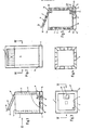
- the cooling container according to the invention consists of a dimensionally stable bottom part 1, e.g. from a plastic tub, and from an inflatable structure 2 connected or connectable to it. In all figures, this structure 2 is shown in the inflated state.
- the structure 2 has a side wall 3, which in the present case shows a square cross-sectional shape, so that the entire container in principle represents a hollow square prism.
- the container can also have, for example, a round or elliptical cross section, have a bulbous shape, etc.
- the inner wall 4, the outer wall 5 and the transverse walls 6 are made of flexible plastic.
- a valve 8 is provided on the outer wall 5, via which the cavity between the inner and outer walls can be filled or emptied with air.
- the Be tenwandung 3 is thus inflatable or can be folded to a small size after opening the valve 8.
- the transverse walls 6 have a stabilizing and convection-inhibiting effect, but the air passage openings 7 allow air to pass through when filling and emptying.
- the transverse walls 6 do not have to run in the vertical direction, as shown, they can also be arranged horizontally or inclined, and it is also possible to provide transverse walls which run at an angle to one another, in particular at right angles.
- the structure 2 also has a cover 9 which, in the example shown, is constructed in the same way as the side wall 3, i.e. it has an inner wall 4 ', an outer wall 5', transverse walls 6 'with air openings 7' and a valve 8 '.
- the lid 9 can also be inflated or folded or rolled.
- the lid 9 can be completely removable or, e.g. 5, can be connected to the side wall 3 in a hinge-like manner via a flexible plastic sheet 10.
- the cover 9 can have an overhanging edge 12 which bears against the upper edges of the side wall 3.
- both the side wall 3 and the cover 9 have in addition to the inner and outer walls 4, 4 'and 5, 5' also end walls 13, 13 '.
- the cooling container according to the invention has an active cooling system, which is described below.
- the bottom part 1 has an upper plate 14 made of a good heat-conducting material, preferably of aluminum.
- This plate 14 forms the lower boundary of the interior of the structure 2, ie the actual cooling room, in which, for example, food and drinks can be introduced.
- On the plate 14 there is a Peltier element 15, the electrical connections of which are connected to an electrical plug fastened to the wall of the base part 1 direction 16 is connected.
- the Peltier element 15 is also provided with a cooling plate 17, cooling fins or the like. Mistake.
- a heat-insulating layer 18, for example made of hard foam plastic, is glued to the underside of the plate 14.
- a small electric motor 19 is provided in the base part 1, the axis 20 of which is directed upwards, through an unspecified hole in the plate 14, in order on the one hand to forcibly circulate air inside the structure, and on the other hand to enable forced cooling of the cooling plate 17 of the Peltier element and the insulating layer 18 extends into the interior of the structure 2.
- a first impeller 21 sits on the axis 20, which, as indicated by arrows in FIG. 5, sucks in outside air, leads it over the cooling plate 17 and finally pushes the heated air out again.
- guide surfaces 22 are provided, which are only indicated schematically.
- Corresponding air supply or outlet openings 23, 24 are also provided in the base part 1.
- the shaft or axis 20 can be extended through the layer 18 and the plate 14 into the interior of the cooling container and be provided there with a second impeller 25, which circulates the air, so that the formation a cold air lake above the plate 14 is avoided.
- the second impeller 26 is expediently covered by a protective cover 26, e.g. a sieve or perforated sheet.
- the lid of the cooling container can also be rigid, ie not inflatable, and in this case advantageously consists of an upper solid plastic plate which is connected to a lower insulating plate made of foamed plastic. If the edge of the bottom part 1 over the upper plate 14 is pulled up, the structure 2 can be folded into the upper part of the bottom part after the blown air has been emptied, the lid then closing the bottom part upwards, so that the container assumes a compact, pleasing shape when folded, whereby the inflatable structure is protected against damage.
Landscapes
- Engineering & Computer Science (AREA)
- Physics & Mathematics (AREA)
- Mechanical Engineering (AREA)
- Thermal Sciences (AREA)
- General Engineering & Computer Science (AREA)
- Chemical & Material Sciences (AREA)
- Combustion & Propulsion (AREA)
- Devices That Are Associated With Refrigeration Equipment (AREA)
- Packages (AREA)
Priority Applications (1)
| Application Number | Priority Date | Filing Date | Title |
|---|---|---|---|
| EP88890154A EP0346560A1 (fr) | 1988-06-14 | 1988-06-14 | Conteneur frigorifique |
Applications Claiming Priority (1)
| Application Number | Priority Date | Filing Date | Title |
|---|---|---|---|
| EP88890154A EP0346560A1 (fr) | 1988-06-14 | 1988-06-14 | Conteneur frigorifique |
Publications (1)
| Publication Number | Publication Date |
|---|---|
| EP0346560A1 true EP0346560A1 (fr) | 1989-12-20 |
Family
ID=8200711
Family Applications (1)
| Application Number | Title | Priority Date | Filing Date |
|---|---|---|---|
| EP88890154A Withdrawn EP0346560A1 (fr) | 1988-06-14 | 1988-06-14 | Conteneur frigorifique |
Country Status (1)
| Country | Link |
|---|---|
| EP (1) | EP0346560A1 (fr) |
Cited By (5)
| Publication number | Priority date | Publication date | Assignee | Title |
|---|---|---|---|---|
| FR2821663A1 (fr) * | 2001-03-05 | 2002-09-06 | Gerard Roquillon | Coffre refrigerateur congelateur a volume variable |
| WO2007054142A1 (fr) * | 2005-11-08 | 2007-05-18 | Electrolux Home Products Corporation N.V. | Modele de corps de caisse de refrigerateur |
| ITTO20100607A1 (it) * | 2010-07-14 | 2010-10-13 | Mondial Group Srl | Espositore refrigerato gonfiabile. |
| DE102009041915A1 (de) * | 2009-08-05 | 2011-02-10 | Liebherr-Hausgeräte Lienz Gmbh | Kühl- und/oder Gefriergerät |
| US11473827B2 (en) | 2017-05-31 | 2022-10-18 | Carrier Corporation | Actively cooled device for small scale delivery |
Citations (12)
| Publication number | Priority date | Publication date | Assignee | Title |
|---|---|---|---|---|
| FR1209745A (fr) * | 1958-09-10 | 1960-03-03 | Armoire frigorifique portative, notamment pour camping | |
| US3160307A (en) * | 1962-07-13 | 1964-12-08 | Willard L Morrison | Insulated shipper container |
| CH426615A (de) * | 1963-02-28 | 1966-12-15 | Langdon Morrison Willard | Isolierter Transportbehälter |
| US3310953A (en) * | 1965-10-23 | 1967-03-28 | Joseph M Rait | Portable refrigerator for beverage containers and the like |
| DE1243702B (de) * | 1963-05-07 | 1967-07-06 | Kurt Koblischek | Tragbare Kuehltasche fuer Batteriebetrieb |
| US3555848A (en) * | 1968-09-09 | 1971-01-19 | Sarah A Johnson | Self-contained portable cooler for food receptacles |
| FR2059684A1 (fr) * | 1969-08-26 | 1971-06-04 | Rufener Marcel | |
| US3839876A (en) * | 1972-11-21 | 1974-10-08 | Int Promotion Eng Sa | Means for cold production |
| CH555269A (de) * | 1973-06-29 | 1974-10-31 | Schoellkopf & Co Ag | Thermisch isolierter behaelter fuer lebensmittel oder getraenke. |
| FR2460450A1 (fr) * | 1979-06-29 | 1981-01-23 | David Georges | Conservateur portable perfectionne a climatiseur electrique integre |
| FR2490794A1 (fr) * | 1981-07-28 | 1982-03-26 | Lavit Michel | Dispositif de conservation notamment de corps de personnes decedees |
| FR2520096A1 (fr) * | 1982-01-19 | 1983-07-22 | Droit Philippe | Appareil pour conditionnement en temperature |
-
1988
- 1988-06-14 EP EP88890154A patent/EP0346560A1/fr not_active Withdrawn
Patent Citations (12)
| Publication number | Priority date | Publication date | Assignee | Title |
|---|---|---|---|---|
| FR1209745A (fr) * | 1958-09-10 | 1960-03-03 | Armoire frigorifique portative, notamment pour camping | |
| US3160307A (en) * | 1962-07-13 | 1964-12-08 | Willard L Morrison | Insulated shipper container |
| CH426615A (de) * | 1963-02-28 | 1966-12-15 | Langdon Morrison Willard | Isolierter Transportbehälter |
| DE1243702B (de) * | 1963-05-07 | 1967-07-06 | Kurt Koblischek | Tragbare Kuehltasche fuer Batteriebetrieb |
| US3310953A (en) * | 1965-10-23 | 1967-03-28 | Joseph M Rait | Portable refrigerator for beverage containers and the like |
| US3555848A (en) * | 1968-09-09 | 1971-01-19 | Sarah A Johnson | Self-contained portable cooler for food receptacles |
| FR2059684A1 (fr) * | 1969-08-26 | 1971-06-04 | Rufener Marcel | |
| US3839876A (en) * | 1972-11-21 | 1974-10-08 | Int Promotion Eng Sa | Means for cold production |
| CH555269A (de) * | 1973-06-29 | 1974-10-31 | Schoellkopf & Co Ag | Thermisch isolierter behaelter fuer lebensmittel oder getraenke. |
| FR2460450A1 (fr) * | 1979-06-29 | 1981-01-23 | David Georges | Conservateur portable perfectionne a climatiseur electrique integre |
| FR2490794A1 (fr) * | 1981-07-28 | 1982-03-26 | Lavit Michel | Dispositif de conservation notamment de corps de personnes decedees |
| FR2520096A1 (fr) * | 1982-01-19 | 1983-07-22 | Droit Philippe | Appareil pour conditionnement en temperature |
Cited By (5)
| Publication number | Priority date | Publication date | Assignee | Title |
|---|---|---|---|---|
| FR2821663A1 (fr) * | 2001-03-05 | 2002-09-06 | Gerard Roquillon | Coffre refrigerateur congelateur a volume variable |
| WO2007054142A1 (fr) * | 2005-11-08 | 2007-05-18 | Electrolux Home Products Corporation N.V. | Modele de corps de caisse de refrigerateur |
| DE102009041915A1 (de) * | 2009-08-05 | 2011-02-10 | Liebherr-Hausgeräte Lienz Gmbh | Kühl- und/oder Gefriergerät |
| ITTO20100607A1 (it) * | 2010-07-14 | 2010-10-13 | Mondial Group Srl | Espositore refrigerato gonfiabile. |
| US11473827B2 (en) | 2017-05-31 | 2022-10-18 | Carrier Corporation | Actively cooled device for small scale delivery |
Similar Documents
| Publication | Publication Date | Title |
|---|---|---|
| DE4112631C1 (en) | Motor vehicle seat with moisture removal inset - incorporating air channel at rear of backrest with air dryer | |
| DE2931831C2 (fr) | ||
| DE2846272A1 (de) | Fahrbarer verkaufsstand | |
| DE3874344T2 (de) | Verfahren zur lueftung und lueftungsanlage. | |
| EP1197172A1 (fr) | Vitrine, en particulier pour la présentation de produits frais, de préférence de produits de boulangerie et/ou de confiserie | |
| DE2807352A1 (de) | Kuehlgeraet | |
| DE3116631A1 (de) | "freistehender, gekuehlter schaustellbehaelter mit abtauung mit hilfe von luft | |
| DE1932142B1 (de) | Anlage zum Temperieren,Transportieren und Ausgeben von Lebensmitteln | |
| DE9405207U1 (de) | Transportanhänger für Getränke mit kastenförmigem Aufbau | |
| DE202015007690U1 (de) | Warenausgabeeinheit zur Selbstbedienungsentnahme von Backwaren | |
| DE4332773C2 (de) | Kühlmöbel | |
| DE10014728A1 (de) | Frontbaugruppe für eine Fahrgastzelle eines Fahrzeugs | |
| DE2216478A1 (de) | Elektrisches waermespeicherheizgeraet | |
| DE19532728B4 (de) | Warenautomat mit unterteilbarem Warenraum | |
| DE2918190A1 (de) | Frachtschiff mit decks und kuehlanlage | |
| DE2158147A1 (de) | Wandkühlschrank | |
| CH475532A (de) | Mit Schaumstoff isolierter Behälter | |
| DE3148483A1 (de) | Saunakabine | |
| DE3825141A1 (de) | Kuehleinrichtung | |
| DE69613678T2 (de) | Luftbehandlungsgerät | |
| DE2855115A1 (de) | Kuehlschrank mit luftumwaelzung | |
| DE102005059490A1 (de) | Luftkühlschacht zur Kühlung der Kälteaggregate von Kühl- und Gefriergeräten zum Einbau in eine (Möbel-) Nische | |
| DE9012220U1 (de) | Verstaueinheit | |
| DE2630300A1 (de) | Konvektor-waermestrahler in blockkonstruktion | |
| CH698735B1 (de) | Kombinierte Heiz- und Kühlvorrichtung. |
Legal Events
| Date | Code | Title | Description |
|---|---|---|---|
| PUAI | Public reference made under article 153(3) epc to a published international application that has entered the european phase |
Free format text: ORIGINAL CODE: 0009012 |
|
| AK | Designated contracting states |
Kind code of ref document: A1 Designated state(s): DE ES FR GB IT |
|
| STAA | Information on the status of an ep patent application or granted ep patent |
Free format text: STATUS: THE APPLICATION IS DEEMED TO BE WITHDRAWN |
|
| 18D | Application deemed to be withdrawn |
Effective date: 19900621 |