EP0346603B1 - Interrupteur à vide - Google Patents
Interrupteur à vide Download PDFInfo
- Publication number
- EP0346603B1 EP0346603B1 EP89107836A EP89107836A EP0346603B1 EP 0346603 B1 EP0346603 B1 EP 0346603B1 EP 89107836 A EP89107836 A EP 89107836A EP 89107836 A EP89107836 A EP 89107836A EP 0346603 B1 EP0346603 B1 EP 0346603B1
- Authority
- EP
- European Patent Office
- Prior art keywords
- switch arrangement
- insulating
- accordance
- insulating supporting
- parts
- Prior art date
- Legal status (The legal status is an assumption and is not a legal conclusion. Google has not performed a legal analysis and makes no representation as to the accuracy of the status listed.)
- Expired - Lifetime
Links
Images
Classifications
-
- H—ELECTRICITY
- H01—ELECTRIC ELEMENTS
- H01H—ELECTRIC SWITCHES; RELAYS; SELECTORS; EMERGENCY PROTECTIVE DEVICES
- H01H33/00—High-tension or heavy-current switches with arc-extinguishing or arc-preventing means
- H01H33/60—Switches wherein the means for extinguishing or preventing the arc do not include separate means for obtaining or increasing flow of arc-extinguishing fluid
- H01H33/66—Vacuum switches
- H01H33/666—Operating arrangements
-
- H—ELECTRICITY
- H01—ELECTRIC ELEMENTS
- H01H—ELECTRIC SWITCHES; RELAYS; SELECTORS; EMERGENCY PROTECTIVE DEVICES
- H01H33/00—High-tension or heavy-current switches with arc-extinguishing or arc-preventing means
- H01H33/02—Details
- H01H33/022—Details particular to three-phase circuit breakers
-
- H—ELECTRICITY
- H01—ELECTRIC ELEMENTS
- H01H—ELECTRIC SWITCHES; RELAYS; SELECTORS; EMERGENCY PROTECTIVE DEVICES
- H01H33/00—High-tension or heavy-current switches with arc-extinguishing or arc-preventing means
- H01H33/60—Switches wherein the means for extinguishing or preventing the arc do not include separate means for obtaining or increasing flow of arc-extinguishing fluid
- H01H33/66—Vacuum switches
- H01H33/666—Operating arrangements
- H01H2033/6665—Details concerning the mounting or supporting of the individual vacuum bottles
-
- H—ELECTRICITY
- H01—ELECTRIC ELEMENTS
- H01H—ELECTRIC SWITCHES; RELAYS; SELECTORS; EMERGENCY PROTECTIVE DEVICES
- H01H33/00—High-tension or heavy-current switches with arc-extinguishing or arc-preventing means
- H01H33/60—Switches wherein the means for extinguishing or preventing the arc do not include separate means for obtaining or increasing flow of arc-extinguishing fluid
- H01H33/66—Vacuum switches
- H01H33/666—Operating arrangements
- H01H2033/6667—Details concerning lever type driving rod arrangements
Definitions
- the present invention relates to a switch arrangement according to the preamble of claim 1.
- Such a switch arrangement is known from US-A-4,587,390.
- This has a housing containing a spring force drive, on which three tubular insulating support frames are arranged standing.
- a vacuum interrupter is fastened in each insulating support frame, the contacts of which are connected to a connecting conductor which penetrates the respective insulating support frame in the radial direction.
- Two parallel, laterally spaced plates are provided in the housing of the spring drive, on which the drive parts of the spring drive are mounted.
- Each movable contact of the vacuum interrupters is operatively connected via a linkage to the output element of the spring force drive, which is common to all poles.
- This switch arrangement has many individual parts and is complex to construct and assemble.
- a vacuum switch arrangement with a mobile frame is known from EP-A-0 060 054.
- a one-piece insulating support frame is fastened to the back of this frame, which has three recesses arranged next to one another and open to the front, in each of which a vacuum interrupter is fastened.
- a housing is also attached to the frame, in which a drive is arranged, the driven part of which is operatively connected to the movable contact of each vacuum interrupter via a linkage is, wherein a double lever of each linkage is mounted on extensions of the insulating support frame.
- the insulating support frame is therefore not only an insulating support element for the vacuum interrupter, but it is also an integral part of the drive.
- the drive and the insulating support frame thus form a functional unit that can no longer be separated from one another.
- a particularly stable embodiment, in which the forces occurring in a spring force drive can be controlled particularly well, is specified in claim 2.
- the manufacture of the switch arrangement is particularly simplified by the features specified in claim 3.
- the bearing elements such as bearing shells, stops, pegs, etc., are molded or molded directly on the bearing part, injected or molded, or encapsulated or foamed.
- the Booms absorb only little force, which allows a simple construction, and a pole-wise assembly is made possible.
- each pole has an identical insulating support frame, but the drive parts of the spring force drive are preferably not mounted on all bearing parts of all the insulating support frames.
- the drive parts of the spring force drive are preferably not mounted on all bearing parts of all the insulating support frames.
- An embodiment according to claim 5 also allows drive parts to be mounted on bearing parts of insulating support frames of different poles.
- An embodiment according to claim 8 allows that both the vacuum interrupters, the transmission linkage and the spring force drive are attached to the insulating support frame or are mounted, which reduces the number of parts required, and simplifies assembly and adjustment work.
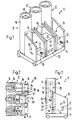
- the three-pole switch arrangement 10 has three identical, one-piece insulating support frames 12, 12 ', which are fastened to a plate-shaped, movable, metal frame 14.
- Each insulating support frame 12, 12 ' consists of a standing on the frame 14, tubular insulating housing 16 and two mutually parallel, laterally spaced from each other approximately by the diameter of the insulating housing 16, in approximately tangential direction from the insulating housing 16 projecting insulating wall elements 18th
- a spring force drive 20 which is generally known in its basic structure, is provided, the output shaft 22 of which, however, is mounted on the insulating wall elements 18 of all three insulating support frames 12, 12'.
- the bearing elements 26, such as pins, holes, bearing shells and the like for the drive parts 24 are molded or cast or injected.
- a vacuum interrupter 28 is arranged in each insulating housing 16, each of which is held by a first connecting lead 30 cast in the insulating housing 16, which is electrically connected to the fixed switching contact 32 of the vacuum interrupter 28 (see in particular FIG. 3).
- the second connecting lead 34 which is also cast in the insulating housing 16, has a schematically illustrated sliding contact 36, which is electrically connected to the movable switching contact 38 of the vacuum interrupter 28.
- the connection conductors 30, 34 protrude on the side facing away from the insulating wall elements 18 via the insulating housing 16. Parts of isolating contacts (not shown) can be fastened to it in order to bring the switch arrangement 10 into or out of connection with the further isolating contact parts arranged in switch cells.
- each vacuum interrupter 28 is operatively connected via a linkage 40 to the output shaft 22 of the spring force drive 20.
- a lever 42 is arranged in a rotationally fixed manner on the output shaft 22, the free end of which is connected via a push rod 44 to the one lever arm of an angle lever 46 pivotably mounted on the insulating support frame 12, 12', the other lever arm is operatively connected to the movable switching contact 38 by means of an insulating rod 48.
- actuating and display elements as well as the control elements required in a spring-loaded drive 20, such as auxiliary switches, contactors and the like, as well as terminal blocks in order to connect these control elements to control and feedback lines, can be attached to the insulating wall elements 18.
- drive parts 24 are assigned different insulating support frames 12, 12 ', so that the drive 20 is distributed over all three poles.
- a single insulating support frame to hold the vacuum interrupters 28 of all poles, and one or more mounting parts for the storage of drive parts are provided on this single insulating support frame.
Landscapes
- Switches With Compound Operations (AREA)
- Supplying Of Containers To The Packaging Station (AREA)
- High-Tension Arc-Extinguishing Switches Without Spraying Means (AREA)
- Driving Mechanisms And Operating Circuits Of Arc-Extinguishing High-Tension Switches (AREA)
- Switches Operated By Changes In Physical Conditions (AREA)
- Vacuum Packaging (AREA)
- Push-Button Switches (AREA)
- Measurement Of Radiation (AREA)
- Image-Pickup Tubes, Image-Amplification Tubes, And Storage Tubes (AREA)
Claims (9)
- Agencement d'interrupteur, en particulier pour moyenne tension, avec au moins un cadre support isolant (12, 12') qui entoure au moins partiellement au minimum un tube de commutation à vide (28) disposé sur lui, un entraînement à ressort (20) avec un organe entraîné (22) ainsi que des parties d'entraînement (24) montées sur au moins un flasque et avec une tringlerie (40), assurant la liaison entre l'organe entraîné (22) de l'entraînement à ressort (20) et le contact mobile (38) du tube de commutation à vide (28), caractérisé en ce que le flasque, servant au tourillonnement de l'organe entraîné (22) et des parties d'entraînement (24), est formé par au moins une partie de palier (18) réalisée d'un seul tenant et disposée sur le cadre support isolant (12, 12'), et le cadre support isolant (12, 12') formant avec l'entraînement à ressort (20) une unité fonctionnelle inséparable.
- Agencement d'interrupteur selon la revendication 1,caractérisé en ce que, sur le cadre support isolant (12, 12'), sont prévues au moins deux parties de palier (18) parallèles, espacées latéralement l'une de l'autre, et l'organe entraîne (22) et les parties d'entraînement (24) étant de préférence montées à rotation sur les deux parties de palier (18).
- Agencement d'interrupteur selon l'une des revendications 1 ou 2, caractérisé en ce que des éléments de palier (26), destinés à la partie entraînée (22) et aux parties d'entraînement (24), sont formés d'un seul tenant et/ou ancrés rigidement sur la partie de palier (18), respectivement sur les parties de palier (18).
- Agencement d'interrupteur selon l'une des revendications 1 à 3, caractérisé en ce que, dans le cas d'un interrupteur multipolaire (10), l'organe entraîné (22), commun à tous les pôles, de l'entraînement à ressort (20) unique est relié aux contacts mobiles (38) du tube de commutation à vide (28), par l'intermédiaire d'une tringlerie (40) séparée.
- Agencement d'interrupteur selon la revendication 1, caractérisé en ce que, pour chaque pôle d'un interrupteur multipolaire (10), est prévu un cadre support isolant (12, 12') identique et l'organe entraîné (22) et les parties d'entraînement (24) étant montés à rotation sur seulement une partie de palier (18), ou sur plusieurs parties de palier (18).
- Agencement d'interrupteur selon la revendication 5,caractérisé en ce que les cadres supports isolants (12, 12') peuvent être reliés ensemble.
- Agencement d'interrupteur selon l'une des revendications 1 à 6, caractérisé en ce que le, respectivement les cadres supports isolants (12, 12') sont fixés sur un bâti (14), de préférence conducteur de l'électricité.
- Agencement d'interrupteur selon la revendication 1,caractérisé en ce que des points de palier pour la tringlerie (40, 46) sont prévus sur le cadre support isolant (12, 12') de préférence sur la partie de palier (18).
- Agencement d'interrupteur selon la revendication 1,caractérisé en ce que le cadre support isolant (12, 12') présente au moins un boîtier isolant tubulaire (16), dans lequel est disposé un tube de commutation à vide (28), et la partie de palier étant formée par au moins un élément de paroi isolante (18) s'écartant latéralement du boîtier isolant (16).
Priority Applications (1)
| Application Number | Priority Date | Filing Date | Title |
|---|---|---|---|
| AT89107836T ATE95629T1 (de) | 1988-06-14 | 1989-04-29 | Vakuumschalteranordnung. |
Applications Claiming Priority (2)
| Application Number | Priority Date | Filing Date | Title |
|---|---|---|---|
| CH228388 | 1988-06-14 | ||
| CH2283/88 | 1988-06-14 |
Publications (2)
| Publication Number | Publication Date |
|---|---|
| EP0346603A1 EP0346603A1 (fr) | 1989-12-20 |
| EP0346603B1 true EP0346603B1 (fr) | 1993-10-06 |
Family
ID=4230150
Family Applications (1)
| Application Number | Title | Priority Date | Filing Date |
|---|---|---|---|
| EP89107836A Expired - Lifetime EP0346603B1 (fr) | 1988-06-14 | 1989-04-29 | Interrupteur à vide |
Country Status (9)
| Country | Link |
|---|---|
| US (1) | US5015809A (fr) |
| EP (1) | EP0346603B1 (fr) |
| JP (1) | JPH0278122A (fr) |
| AT (1) | ATE95629T1 (fr) |
| BR (1) | BR8902819A (fr) |
| CA (1) | CA1325452C (fr) |
| DE (1) | DE58905809D1 (fr) |
| ES (1) | ES2043936T3 (fr) |
| NO (1) | NO177878C (fr) |
Cited By (1)
| Publication number | Priority date | Publication date | Assignee | Title |
|---|---|---|---|---|
| RU2251172C2 (ru) * | 2003-01-22 | 2005-04-27 | Открытое акционерное общество "Карпинский электромашиностроительный завод" | Изоляционная тяга |
Families Citing this family (13)
| Publication number | Priority date | Publication date | Assignee | Title |
|---|---|---|---|---|
| DE4010843A1 (de) * | 1990-04-04 | 1991-10-10 | Sachsenwerk Ag | Stuetzerschalter |
| CH687051A5 (de) * | 1992-02-28 | 1996-08-30 | Gec Alsthom T & D Ag | Verfahren zum Spannen einer Speicherfeder eines Antriebes eines Hoch- oder Mittelspannungs-Leistungsschalters und Leistungsschalter zur Durchfuehrung des Verfahrens. |
| JP2874522B2 (ja) * | 1993-07-14 | 1999-03-24 | 株式会社日立製作所 | 真空遮断器及びそれに用いる真空バルブと真空バルブ用電極並びにその製造法 |
| US5852266A (en) * | 1993-07-14 | 1998-12-22 | Hitachi, Ltd. | Vacuum circuit breaker as well as vacuum valve and electric contact used in same |
| DE4419380C1 (de) * | 1994-05-30 | 1995-10-19 | Siemens Ag | Leistungsschaltermodul |
| EP0801407B1 (fr) * | 1996-04-11 | 2004-07-14 | ABB PATENT GmbH | Interrupteur sous vide monophase ou multiphase |
| DE19701827A1 (de) * | 1997-01-21 | 1998-07-23 | Abb Patent Gmbh | Generatorschalter |
| FR2807204B1 (fr) | 2000-03-31 | 2002-05-24 | Schneider Electric Ind Sa | Appareillage electrique de coupure multipolaire muni d'un mecanisme d'entrainement et de modules de coupure |
| RU2169408C1 (ru) * | 2000-04-21 | 2001-06-20 | Верпета Анатолий Савельевич | Выключатель |
| RU2249873C1 (ru) * | 2003-10-14 | 2005-04-10 | Общество с ограниченной ответственностью "Научно-производственное предприятие "Модуль" | Высоковольтный вакуумный выключатель |
| FR2972072B1 (fr) | 2011-02-25 | 2013-02-15 | Schneider Electric Ind Sas | Dispositif de commande d'au moins un contact mobile et appareil electrique de coupure multipolaire comportant un tel dispositif |
| FR3098976B1 (fr) * | 2019-07-17 | 2021-06-11 | Schneider Electric Ind Sas | Architecture d'un appareil électrique interrupteur |
| EP4145479B1 (fr) * | 2021-09-01 | 2024-02-28 | Abb Schweiz Ag | Dispositif accessoire pour contacteur sous vide moyenne tension |
Family Cites Families (4)
| Publication number | Priority date | Publication date | Assignee | Title |
|---|---|---|---|---|
| US3560682A (en) * | 1965-11-30 | 1971-02-02 | Siemens Ag | Vacuum interrupter with shunting main contact structure and series disconnecting contact structure |
| US4104496A (en) * | 1977-01-18 | 1978-08-01 | Tokyo Shibaura Electric Co., Ltd. | Vacuum interrupter device |
| JPS57147829A (en) * | 1981-03-06 | 1982-09-11 | Tokyo Shibaura Electric Co | Vacuum breaker |
| US4587390A (en) * | 1985-01-07 | 1986-05-06 | Golden Gate Switchboard Co. | Vacuum circuit breaker |
-
1989
- 1989-04-29 DE DE89107836T patent/DE58905809D1/de not_active Expired - Fee Related
- 1989-04-29 AT AT89107836T patent/ATE95629T1/de not_active IP Right Cessation
- 1989-04-29 EP EP89107836A patent/EP0346603B1/fr not_active Expired - Lifetime
- 1989-04-29 ES ES89107836T patent/ES2043936T3/es not_active Expired - Lifetime
- 1989-06-05 US US07/361,257 patent/US5015809A/en not_active Expired - Fee Related
- 1989-06-08 CA CA000602096A patent/CA1325452C/fr not_active Expired - Fee Related
- 1989-06-13 BR BR898902819A patent/BR8902819A/pt not_active IP Right Cessation
- 1989-06-14 NO NO892478A patent/NO177878C/no unknown
- 1989-06-14 JP JP1149756A patent/JPH0278122A/ja active Pending
Cited By (1)
| Publication number | Priority date | Publication date | Assignee | Title |
|---|---|---|---|---|
| RU2251172C2 (ru) * | 2003-01-22 | 2005-04-27 | Открытое акционерное общество "Карпинский электромашиностроительный завод" | Изоляционная тяга |
Also Published As
| Publication number | Publication date |
|---|---|
| US5015809A (en) | 1991-05-14 |
| DE58905809D1 (de) | 1993-11-11 |
| BR8902819A (pt) | 1990-02-01 |
| ES2043936T3 (es) | 1994-01-01 |
| ATE95629T1 (de) | 1993-10-15 |
| CA1325452C (fr) | 1993-12-21 |
| EP0346603A1 (fr) | 1989-12-20 |
| NO177878B (no) | 1995-08-28 |
| JPH0278122A (ja) | 1990-03-19 |
| NO892478L (no) | 1989-12-15 |
| NO892478D0 (no) | 1989-06-14 |
| NO177878C (no) | 1995-12-06 |
Similar Documents
| Publication | Publication Date | Title |
|---|---|---|
| EP0346603B1 (fr) | Interrupteur à vide | |
| EP0387635B1 (fr) | Configuration d'interrupteurs à vide multipolaire | |
| DE69910575T2 (de) | Mehrpoliger niederspannungsleistungschalter mit hoher elektrodynamischer festigkeit, deren polschaft in dem aufnahmeraum der pole angeordnet ist | |
| DE60212701T2 (de) | Kontaktarme tragende schaltwelle für einen niederspannungsschutzschalter | |
| EP0107152B1 (fr) | Thermostat | |
| DE1918851B2 (de) | Mehrpoliger leistungsschalter | |
| DE1615572A1 (de) | Steuerbare Hochstromdruckschalter | |
| EP0199044A2 (fr) | Interrupteur à coupure en charge logé dans une enceinte | |
| DE3724736C2 (de) | Elektrischer Schalter, insbesondere für Kraftfahrzeuge | |
| DE1266850B (de) | Elektrischer Kippschalter | |
| DE2907559C2 (de) | Dreipoliger Hochspannungsschalter insbesondere Lasttrenner | |
| EP1869688B1 (fr) | Commutateur multipolaire avec boitier supplementaire et dispositif de verrouillage automatique reciproque | |
| DE2543959A1 (de) | Adapter fuer sicherungslastschalter zur befestigung auf stromsammelschienen | |
| DE2648964A1 (de) | Metallgekapselter sf tief 6 -isolierter schalter, insbesondere hochspannungs- leistungsschalter | |
| DE2547278C2 (de) | Elektrischer Schnappschalter | |
| EP1065683A2 (fr) | Disjonteur avec des bornes pour plusieurs intensités nominales | |
| DE3121057C2 (de) | Sammelschienensystem mit Trennschaltern für Hochspannungs-Schaltanlage | |
| EP1300866A1 (fr) | Relais électromagnétique à action brusque comportant un pont de contact | |
| DE1910165B2 (de) | Zweipoliger Schiebeschalter | |
| DE29615566U1 (de) | Bewegbare Schaltkontaktanordnung mit einem Kontakthebel aufnehmenden Kontakthebelträger | |
| DE2031175B2 (de) | Warnlichtschalter für Kraftfahrzeuge | |
| WO1997044799A1 (fr) | Sectionneur de puissance basse tension pourvu d'un porte-contact | |
| EP0880156A2 (fr) | Agencement de résistance pour un appareil de commutation électromagnétique destiné à couper une charge capacitive | |
| DE2645395A1 (de) | Elektrischer schalter insbesondere zur automatischen geschwindigkeitsregelung von kraftfahrzeugen | |
| DE969985C (de) | Nockenschalteranordnung mit zu einer Baueinheit zusammengefassten Isolierstoffelementen |
Legal Events
| Date | Code | Title | Description |
|---|---|---|---|
| PUAI | Public reference made under article 153(3) epc to a published international application that has entered the european phase |
Free format text: ORIGINAL CODE: 0009012 |
|
| AK | Designated contracting states |
Kind code of ref document: A1 Designated state(s): AT BE CH DE ES FR GB IT LI NL SE |
|
| 17P | Request for examination filed |
Effective date: 19900420 |
|
| 17Q | First examination report despatched |
Effective date: 19920609 |
|
| GRAA | (expected) grant |
Free format text: ORIGINAL CODE: 0009210 |
|
| AK | Designated contracting states |
Kind code of ref document: B1 Designated state(s): AT BE CH DE ES FR GB IT LI NL SE |
|
| REF | Corresponds to: |
Ref document number: 95629 Country of ref document: AT Date of ref document: 19931015 Kind code of ref document: T |
|
| ITF | It: translation for a ep patent filed | ||
| REF | Corresponds to: |
Ref document number: 58905809 Country of ref document: DE Date of ref document: 19931111 |
|
| ET | Fr: translation filed | ||
| GBT | Gb: translation of ep patent filed (gb section 77(6)(a)/1977) |
Effective date: 19940112 |
|
| REG | Reference to a national code |
Ref country code: CH Ref legal event code: PFA Free format text: GEC ALSTHOM T&D AG |
|
| REG | Reference to a national code |
Ref country code: ES Ref legal event code: PC2A Owner name: GEC ALSTHOM T&D AG. |
|
| PLBE | No opposition filed within time limit |
Free format text: ORIGINAL CODE: 0009261 |
|
| STAA | Information on the status of an ep patent application or granted ep patent |
Free format text: STATUS: NO OPPOSITION FILED WITHIN TIME LIMIT |
|
| 26N | No opposition filed | ||
| ITPR | It: changes in ownership of a european patent |
Owner name: CAMBIO RAGIONE SOCIA;GEC ALSSTHOM T & D AG |
|
| EAL | Se: european patent in force in sweden |
Ref document number: 89107836.2 |
|
| REG | Reference to a national code |
Ref country code: FR Ref legal event code: CD Ref country code: FR Ref legal event code: CA |
|
| NLT1 | Nl: modifications of names registered in virtue of documents presented to the patent office pursuant to art. 16 a, paragraph 1 |
Owner name: GEC ALSTHOM T&D AG TE OBERENTFELDEN, ZWITSERLAND. |
|
| PGFP | Annual fee paid to national office [announced via postgrant information from national office to epo] |
Ref country code: FR Payment date: 19970314 Year of fee payment: 9 |
|
| PGFP | Annual fee paid to national office [announced via postgrant information from national office to epo] |
Ref country code: BE Payment date: 19970320 Year of fee payment: 9 |
|
| PGFP | Annual fee paid to national office [announced via postgrant information from national office to epo] |
Ref country code: ES Payment date: 19970418 Year of fee payment: 9 |
|
| PG25 | Lapsed in a contracting state [announced via postgrant information from national office to epo] |
Ref country code: FR Free format text: THE PATENT HAS BEEN ANNULLED BY A DECISION OF A NATIONAL AUTHORITY Effective date: 19980430 Ref country code: ES Free format text: LAPSE BECAUSE OF EXPIRATION OF PROTECTION Effective date: 19980430 Ref country code: BE Free format text: LAPSE BECAUSE OF NON-PAYMENT OF DUE FEES Effective date: 19980430 |
|
| BERE | Be: lapsed |
Owner name: GEC ALSTHOM T&D A.G. Effective date: 19980430 |
|
| REG | Reference to a national code |
Ref country code: FR Ref legal event code: ST |
|
| PGFP | Annual fee paid to national office [announced via postgrant information from national office to epo] |
Ref country code: GB Payment date: 19990315 Year of fee payment: 11 |
|
| PGFP | Annual fee paid to national office [announced via postgrant information from national office to epo] |
Ref country code: AT Payment date: 19990324 Year of fee payment: 11 |
|
| PGFP | Annual fee paid to national office [announced via postgrant information from national office to epo] |
Ref country code: SE Payment date: 19990325 Year of fee payment: 11 |
|
| PGFP | Annual fee paid to national office [announced via postgrant information from national office to epo] |
Ref country code: DE Payment date: 19990326 Year of fee payment: 11 Ref country code: CH Payment date: 19990326 Year of fee payment: 11 |
|
| PGFP | Annual fee paid to national office [announced via postgrant information from national office to epo] |
Ref country code: NL Payment date: 19990329 Year of fee payment: 11 |
|
| REG | Reference to a national code |
Ref country code: CH Ref legal event code: PFA Free format text: GEC ALSTHOM T&D AG TRANSFER- ALSTOM AG |
|
| REG | Reference to a national code |
Ref country code: ES Ref legal event code: FD2A Effective date: 20000301 |
|
| PG25 | Lapsed in a contracting state [announced via postgrant information from national office to epo] |
Ref country code: GB Free format text: LAPSE BECAUSE OF NON-PAYMENT OF DUE FEES Effective date: 20000429 Ref country code: AT Free format text: LAPSE BECAUSE OF NON-PAYMENT OF DUE FEES Effective date: 20000429 |
|
| PG25 | Lapsed in a contracting state [announced via postgrant information from national office to epo] |
Ref country code: SE Free format text: LAPSE BECAUSE OF NON-PAYMENT OF DUE FEES Effective date: 20000430 Ref country code: LI Free format text: LAPSE BECAUSE OF NON-PAYMENT OF DUE FEES Effective date: 20000430 Ref country code: CH Free format text: LAPSE BECAUSE OF NON-PAYMENT OF DUE FEES Effective date: 20000430 |
|
| PG25 | Lapsed in a contracting state [announced via postgrant information from national office to epo] |
Ref country code: NL Free format text: LAPSE BECAUSE OF NON-PAYMENT OF DUE FEES Effective date: 20001101 |
|
| EUG | Se: european patent has lapsed |
Ref document number: 89107836.2 |
|
| REG | Reference to a national code |
Ref country code: CH Ref legal event code: PL |
|
| GBPC | Gb: european patent ceased through non-payment of renewal fee |
Effective date: 20000429 |
|
| NLV4 | Nl: lapsed or anulled due to non-payment of the annual fee |
Effective date: 20001101 |
|
| PG25 | Lapsed in a contracting state [announced via postgrant information from national office to epo] |
Ref country code: DE Free format text: LAPSE BECAUSE OF NON-PAYMENT OF DUE FEES Effective date: 20010201 |
|
| PG25 | Lapsed in a contracting state [announced via postgrant information from national office to epo] |
Ref country code: IT Free format text: LAPSE BECAUSE OF NON-PAYMENT OF DUE FEES;WARNING: LAPSES OF ITALIAN PATENTS WITH EFFECTIVE DATE BEFORE 2007 MAY HAVE OCCURRED AT ANY TIME BEFORE 2007. THE CORRECT EFFECTIVE DATE MAY BE DIFFERENT FROM THE ONE RECORDED. Effective date: 20050429 |