EP0346614A2 - Procédé pour l'initialisation d'un système de transmission de données numériques - Google Patents
Procédé pour l'initialisation d'un système de transmission de données numériques Download PDFInfo
- Publication number
- EP0346614A2 EP0346614A2 EP19890108655 EP89108655A EP0346614A2 EP 0346614 A2 EP0346614 A2 EP 0346614A2 EP 19890108655 EP19890108655 EP 19890108655 EP 89108655 A EP89108655 A EP 89108655A EP 0346614 A2 EP0346614 A2 EP 0346614A2
- Authority
- EP
- European Patent Office
- Prior art keywords
- connection point
- programming device
- interface
- transmission system
- connection points
- Prior art date
- Legal status (The legal status is an assumption and is not a legal conclusion. Google has not performed a legal analysis and makes no representation as to the accuracy of the status listed.)
- Granted
Links
Images
Classifications
-
- H—ELECTRICITY
- H02—GENERATION; CONVERSION OR DISTRIBUTION OF ELECTRIC POWER
- H02J—ELECTRIC POWER NETWORKS; CIRCUIT ARRANGEMENTS OR SYSTEMS FOR SUPPLYING OR DISTRIBUTING ELECTRIC POWER; SYSTEMS FOR STORING ELECTRIC ENERGY
- H02J13/00—Circuit arrangements for providing remote monitoring or remote control of equipment in a power distribution network
- H02J13/13—Circuit arrangements for providing remote monitoring or remote control of equipment in a power distribution network characterised by the transmission of data to equipment in the power network
-
- G—PHYSICS
- G05—CONTROLLING; REGULATING
- G05B—CONTROL OR REGULATING SYSTEMS IN GENERAL; FUNCTIONAL ELEMENTS OF SUCH SYSTEMS; MONITORING OR TESTING ARRANGEMENTS FOR SUCH SYSTEMS OR ELEMENTS
- G05B2219/00—Program-control systems
- G05B2219/20—Pc systems
- G05B2219/21—Pc I-O input output
- G05B2219/21036—Each connected module has own address and address of originator of message
-
- G—PHYSICS
- G05—CONTROLLING; REGULATING
- G05B—CONTROL OR REGULATING SYSTEMS IN GENERAL; FUNCTIONAL ELEMENTS OF SUCH SYSTEMS; MONITORING OR TESTING ARRANGEMENTS FOR SUCH SYSTEMS OR ELEMENTS
- G05B2219/00—Program-control systems
- G05B2219/20—Pc systems
- G05B2219/21—Pc I-O input output
- G05B2219/21075—Initialise each module random, count down, if zero leader sets address
-
- G—PHYSICS
- G05—CONTROLLING; REGULATING
- G05B—CONTROL OR REGULATING SYSTEMS IN GENERAL; FUNCTIONAL ELEMENTS OF SUCH SYSTEMS; MONITORING OR TESTING ARRANGEMENTS FOR SUCH SYSTEMS OR ELEMENTS
- G05B2219/00—Program-control systems
- G05B2219/20—Pc systems
- G05B2219/25—Pc structure of the system
- G05B2219/25427—Controller inside socket, wall connector, distributor, junction box
-
- G—PHYSICS
- G05—CONTROLLING; REGULATING
- G05B—CONTROL OR REGULATING SYSTEMS IN GENERAL; FUNCTIONAL ELEMENTS OF SUCH SYSTEMS; MONITORING OR TESTING ARRANGEMENTS FOR SUCH SYSTEMS OR ELEMENTS
- G05B2219/00—Program-control systems
- G05B2219/20—Pc systems
- G05B2219/26—Pc applications
- G05B2219/2642—Domotique, domestic, home control, automation, smart house
-
- H—ELECTRICITY
- H04—ELECTRIC COMMUNICATION TECHNIQUE
- H04L—TRANSMISSION OF DIGITAL INFORMATION, e.g. TELEGRAPHIC COMMUNICATION
- H04L12/00—Data switching networks
- H04L12/28—Data switching networks characterised by path configuration, e.g. LAN [Local Area Networks] or WAN [Wide Area Networks]
- H04L12/2803—Home automation networks
-
- H—ELECTRICITY
- H04—ELECTRIC COMMUNICATION TECHNIQUE
- H04L—TRANSMISSION OF DIGITAL INFORMATION, e.g. TELEGRAPHIC COMMUNICATION
- H04L12/00—Data switching networks
- H04L12/28—Data switching networks characterised by path configuration, e.g. LAN [Local Area Networks] or WAN [Wide Area Networks]
- H04L12/2803—Home automation networks
- H04L12/2838—Distribution of signals within a home automation network, e.g. involving splitting/multiplexing signals to/from different paths
-
- Y—GENERAL TAGGING OF NEW TECHNOLOGICAL DEVELOPMENTS; GENERAL TAGGING OF CROSS-SECTIONAL TECHNOLOGIES SPANNING OVER SEVERAL SECTIONS OF THE IPC; TECHNICAL SUBJECTS COVERED BY FORMER USPC CROSS-REFERENCE ART COLLECTIONS [XRACs] AND DIGESTS
- Y02—TECHNOLOGIES OR APPLICATIONS FOR MITIGATION OR ADAPTATION AGAINST CLIMATE CHANGE
- Y02B—CLIMATE CHANGE MITIGATION TECHNOLOGIES RELATED TO BUILDINGS, e.g. HOUSING, HOUSE APPLIANCES OR RELATED END-USER APPLICATIONS
- Y02B90/00—Enabling technologies or technologies with a potential or indirect contribution to GHG emissions mitigation
- Y02B90/20—Smart grids as enabling technology in buildings sector
-
- Y—GENERAL TAGGING OF NEW TECHNOLOGICAL DEVELOPMENTS; GENERAL TAGGING OF CROSS-SECTIONAL TECHNOLOGIES SPANNING OVER SEVERAL SECTIONS OF THE IPC; TECHNICAL SUBJECTS COVERED BY FORMER USPC CROSS-REFERENCE ART COLLECTIONS [XRACs] AND DIGESTS
- Y04—INFORMATION OR COMMUNICATION TECHNOLOGIES HAVING AN IMPACT ON OTHER TECHNOLOGY AREAS
- Y04S—SYSTEMS INTEGRATING TECHNOLOGIES RELATED TO POWER NETWORK OPERATION, COMMUNICATION OR INFORMATION TECHNOLOGIES FOR IMPROVING THE ELECTRICAL POWER GENERATION, TRANSMISSION, DISTRIBUTION, MANAGEMENT OR USAGE, i.e. SMART GRIDS
- Y04S40/00—Systems for electrical power generation, transmission, distribution or end-user application management characterised by the use of communication or information technologies, or communication or information technology specific aspects supporting them
- Y04S40/12—Systems for electrical power generation, transmission, distribution or end-user application management characterised by the use of communication or information technologies, or communication or information technology specific aspects supporting them characterised by data transport means between the monitoring, controlling or managing units and monitored, controlled or operated electrical equipment
Definitions
- the invention relates to a digital signal transmission system of the type specified in the preamble of patent claim 1, in particular for home automation technology.
- a known signal transmission system for home automation technology has numerous essentially identically constructed interfaces which are arranged at the subscriber stations and are coded by adding electrical connecting components. In this way, numerous source-target connections can be established between selected interfaces.
- switching telegrams switching commands
- control telegrams eg for brightness control
- status telegrams eg for temperature query
- data transmission telegrams The most common programs to be transmitted are switching telegrams.
- the switching command that is given on a device is via the with this connected connection point to the signal line network and fed to a connection point, which represents the selected destination.
- connection point forwards the switching signal to a connected device, eg a relay, which executes the switching command.
- control telegrams, status telegrams and data transmission telegrams can each be transmitted from a selected source to a target communicating with this source. Determining which source communicates with which destination and which telegram type is to be transmitted requires a great deal of effort.
- Each connection point is usually equipped with two mechanical dialing devices, at which the addresses of source and destination can be set mechanically and then remain stored. The disadvantage here, however, is that the mechanical voters take up a lot of space and that the number of addresses to be set at them is very limited.
- the connection points can not be accommodated in the usual installation boxes for switches and sockets due to the large space required by the dialing devices. Programming also requires mechanical intervention at the connection points.
- connection points can be installed at the connection points provided for this purpose. In this state, any programming of the signal transmission system and any assignment of connection points to certain functions and to other connection points is still possible.
- This spatial and functional assignment of the numerous installed connection points is intended for him signal transmission system according to the invention are made possible in a relatively simple manner, the connection points being able to do without their own selection devices.
- the invention is therefore based on the object of providing a digital signal transmission system of the type specified in the preamble of claim 1, in which the programming does not require any intervention in the connection points.
- the programming is carried out with the aid of a programming device which can be connected to the signal line network and is able to exchange signals with each of the connection points and to enter data into each of the connection points or to query data from the connection points.
- a programming device which can be connected to the signal line network and is able to exchange signals with each of the connection points and to enter data into each of the connection points or to query data from the connection points.
- connection points A fundamental problem in the programming of numerous connection points distributed in a signal line network is the identification of the individual connection points. Since there are usually several identical connection points that are used by the elec triker have been installed at the connection points, the connection points initially have no identification features. To program the connection points, however, these must be identifiable. For this purpose, according to the invention, each individual connection point is provided with a unique identifier by the programming device. This identifier is stored in the connection point. The identifier is, for example, a number, for example one of the numbers from 0 to 255. After each connection point has been assigned one of these numbers, the connection point reacts to a call of the relevant identifier by the programming device.
- the signal transmission system does not yet contain any information about the location of the individual connection points.
- the identifier is only an assignment of internal data, however, it is still necessary to assign the identifiers to location identifications that can be recognized by humans, e.g. switch kitchen, ceiling lighting living room, hall station, entrance door station, hall switch, door opener, etc.
- the above information contain not only location determinations, but also determinations about the telegram type, which is explained below.
- the individual connection points are activated one after the other by manual intervention according to the first variant of the invention.
- the activation of a connection point is registered by the programming device, the connection point in question also communicating its identifier to the programming device.
- the associated location can then be manually entered into the programming device are, whereupon the programming device identifies the identification and location of the relevant junction.
- the programming device then contains, for example, the information that the connection point with the identification 166 is located near the door in the kitchen.
- connection point After all the connection points have been assigned a location, the programming device specifies each connection point with which connection point it should correspond. Different systems are possible for this, which are explained further below.
- the simplest system is that the programming device is manually entered, with which connection points a certain connection point should correspond and which telegram type is intended for the transmission. This data is stored in the source ports and the destination ports.
- the storage of the location information can also take place at the same time as the assignment of the identifier in a single step if the interfaces are equipped with adapters in a sequence which has been precisely defined beforehand according to an installation plan.
- the location of each connection point is determined in that the programming device calls the individual interfaces one after the other and the connection points contain an optical or acoustic signal transmitter which reacts to the call of the connection point.
- the connection points are called up, for example, in the order of their identifiers (from 0 to 255) and the signal is sent to the connection point called up encoder activated.
- the fitter can then recognize which connection point has the relevant identifier and enter the location of this connection point in the programming device.
- the next identifier is called when the location of the previous identifier has been entered.
- all connection points can be activated in the installation phase before the locations of the connection points are identified.
- the digital signal transmission system preferably contains connection points from mutually identical interfaces, to which adapters are assigned which exist in different types, so that the appropriate combination of interface and adapter can be installed at each connection point so that the corresponding device can be connected to it a lamp, a sensor, a motor or the like. acts.
- the signal line network of the signal transmission system can consist of the network lines of the electrical supply network, via which the digital signal data are simultaneously transmitted.
- the signal line network expediently contains the signal lines separately from the electrical supply lines in order to avoid mutual interference and to prevent interference from the supply network from influencing the signal line network.
- connection points which are programmed in that data such as identifier, destination address, source address and telegram type are entered into the memory devices , do not require any dialing devices and also no separate connection for a dialing device.
- the memory contents are input to each connection point by the programming device via the signal line network.
- connection points or at least the interfaces as small-volume integrated circuits that fit into wall boxes and only have plug contacts for plugging in an adapter.
- the adapter can be plugged into the interface contained in a wall socket from the outside or can also be contained together with the interface in the wall socket.
- connection points are supplied with power either via the signal line network or via separate supply lines which run in accordance with the signal line network. In any case, a central power supply is provided for the operation of the connection points.
- the adapters are available in different adapter types, with one adapter type as the source and another adapter type as the destination for each telegram type to be transmitted. It is also possible to design the adapter so that when it is plugged into the interface of the interface it provides information about the adapter type, for example the information that this adapter is suitable as a source for a switching telegram. This information is then stored in the interface of the storage device. The information can be transmitted with an additional information pin that protrudes from the adapter and which carries encoded information that can be read by the interface. On the other hand, it is also possible for the interface to supply a specific signal sequence when an adapter is connected to this adapter, which is answered by the adapter with a signal or a signal sequence which indicates the adapter type.
- the adapter is used to adapt the interface to the device to be connected externally.
- a source adapter is suitable for implementing a switching process or an analog or digital signal so that this signal can be fed to the interface, which then generates a corresponding telegram that is transmitted via the signal line network.
- the telegram contains the source address, destination address, telegram type and information.
- the interfaces are active components that require an electrical power supply, while the adapters are passive components.
- the memory devices in the interfaces are self-holding memories that retain their memory content even if the power supply fails.
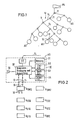
- the signal line network 10 which consists of signal lines SL, which in the present exemplary embodiment are connected in a tree structure, a junction box 11, which contains a connecting device, being arranged at each junction point.
- Each signal line SL leads to a connection point AS.
- the signal line network can also be designed in a bus structure, the individual connection points AS being arranged along a common bus line.
- Fig. 2 shows one of the connection points AS.
- This connection point AS contains a universal interface UI housed in a wall socket (not shown).
- the interface UI contains a transmitting and receiving part SE connected to the signal line SL, a data processor DP, which is connected to the transmitting and receiving part SE, and storage devices S1, S2, S3 and S4.
- the storage devices are empty when the UI interface is installed and are only provided with the relevant data after installation.
- the storage device S1 is used for recording An identifier (characteristic data) for the interface in question, the storage device S2 serves to hold one or more destination addresses, the storage device S3 serves to hold one or more source addresses and the storage device S4 serves to hold an indication of the type of telegram that the Interface UI should process or transfer.
- Lines 13 lead from the data processor DP to connections 14 to which an external adapter A can be connected.
- This adapter has plug contacts 15 for connecting to the contacts 14 of the interface UI, as well as connections 16 for connecting a device, for example a switch, a relay, a lamp, a sensor, a motor or the like.
- Switch telegram Control telegram Status telegram Data transmission telegram Two types of adapters are provided, one as the source and one as the destination. In total, there are eight different adapter types, each of which can be connected to the UI interface, namely A SWQ switch adapter as the source A SWZ switch adapter as the target A COQ rule adapter as a source A COZ rule adapter as a target A STQ status adapter as a source A STZ status adapter as a target A DTQ data transfer adapter as a source A DTZ data transmission adapter as a target.
- the programming device PG is connected to one of the junction boxes 11 of the signal line network 10, which serves to program the interfaces UI and which can then be removed again, so that the signal line network can be operated without a control center and without a programming device.
- the programming device PG can communicate with all interfaces UI via the signal lines SL, i.e. it can send data to the interfaces and receive data sent by the interfaces.
- the programming device PG has numerous keys for the manual entry of data and a data processor DP.
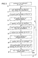
- the sequence of programming the interfaces UI is shown in FIG. 3.
- the interfaces UI are installed at the connection points AS and connected to the signal lines SL, the assignment of identifiers to the UIs takes place in step 20 according to FIG. 3.
- Each interface receives a random, unique identifier (chaotic distribution), ie each interface receives a key figure of 1 to 255 without knowing which interface has received which key figure. It is only ensured that each interface has received an identifier which is stored in the storage device S1 of this interface.
- the identifiers are assigned as follows:
- Pressing a key on the programming device PG starts the initialization process, in which a random generator contained in the data processor DP is started in each interface UI. Then all UIs with the DEFAULT address O are activated. This means that all UIs with the address 0 access the signal line network in order to connect to the programming device PG. Since several UIs want to correspond with the programming device, collisions occur, making it impossible to establish a connection to the programming device. The UI detects the collision using a LISTEN-TALK function. Now the number contained in the random number generator is read out in each UI and these numbers are decremented independently of the programming device PG by the step locations UI and queried for 0.
- the UI tries again to come into contact with the programming device.
- the UI whose numerical value first dropped to 0 receives the identifier "1" from the programming device PG, the next UI receives the identifier "2", etc.
- step 20 As soon as all UIs have individually connected to the programming device PG in this way and all UIs have been given an individual identifier, step 20 according to FIG. 3 is completed. The final programming and the completion phase now take place.
- step 21 all the UIs not yet equipped with an adapter are made sensitive by the programming device PG as the source for the "switching telegram" telegram type.
- the "switching telegram" telegram type is the most common telegram type that is processed first.
- an adapter A SWQ is plugged into one of the UIs, which is provided as the source for switching telegrams.
- the UI in question reports its identifier, which was assigned to it in step 20, to the programming device.
- the location of the UI is then manually entered into the programming device PG in step 24. This location is assigned to the identifier of the relevant UI in the programming device.
- step 25 all UIs not yet assigned an adapter A are made sensitive as a target for the "switching telegram" telegram type. Then, in step 26, an adapter A SWZ is plugged into a UI which is to communicate with the UI previously set up as a source. The target UI reports its identifier to the programming device PG in step 27. In step 28, the location of the UI last used with an adapter is manually entered into the programming device, and in step 29 the programming device informs the target UI of the source and the identifier Source UI using the identifier of the target. This data is stored in the storage devices S2 and S3. In addition, the telegram type, for example "switching telegram", is stored in the memory device S4.
- Step 30 determines whether all targets have been set up for the same source. If a source is to communicate with several destinations at the same time, the other destinations must be set up for the same source. This is done by loop 31, which leads back to step 25.
- next UI is set up as the source via loop 32, which leads back to step 21.
- the next telegram type e.g. "Control telegram" where the interfaces provided for this telegram type are set up and programmed.
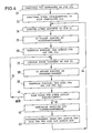
- FIGS. 4 and 5 Another way of programming the interfaces is shown in FIGS. 4 and 5 specified.
- identifiers are assigned to the UIs in the same way as described in version 1.
- a telegram type for example "switching telegram”
- This step does not yet determine whether it is a source or a target.
- an adapter is plugged into one of the UIs and in step 35 this UI reports its identifier to the programming device PG.
- step 36 a manual entry is made on the programming device, that the UI that was last equipped with an adapter is a source, and the entry of the location where this UI is installed.
- step 37 a UI that is intended as a target for the UI previously populated as a source is populated with an adapter.
- step 38 the UI reports its identifier to the programming device PG.
- step 39 the PG is manually entered that this UI is a destination and the location where this UI is located (step 39).
- step 40 a decision must be made as to whether all targets are set up for the source UI. If this is not yet the case, loop 41 returns to step 37 and another UI is set up as the target for the same source UI. If all destinations are set up for the same source, the programming device PG assigns the group an allocation number from sources and destinations. In step 43, the programming device notifies the source of the destination and the destination the source, which are stored in the storage devices S2 and S3 of the UIs involved.
- loop 44 returns to step 34 and another group of sources and targets is programmed.
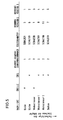
- the installation plan shown in FIG. 5 is drawn up, from which it can be seen at which location of the house which device is to be installed and from which location of the house this device is controlled or to which A message should be given to the house.
- the sources and goals are in the order of their mutual assignment is specified and the interfaces are equipped with adapters in the order specified in the installation plan.
- the "kitchen” source includes the “kitchen” target and that the "living room” source includes the three targets "living room 1", "living room 2" and "balcony”.
- Each combination of source and target (s) is assigned an assignment number that has to be entered manually into the programming device. For example, the source with the assignment number "2" includes all destinations with the assignment number "2".
- Version 3 of the programming of the interfaces basically corresponds to version 2, but the assignment phase (step 20) is carried out at the same time as the interfaces are equipped with adapters. An upstream assignment phase is therefore not necessary.
- the programming devices PG provide the UIs with codes (identifiers) in the order in which they are fitted with adapters. The use of random generators in the UIs is therefore no longer necessary.
- all interfaces are provided with a unique identifier, which can be done either by the described step 20 of FIG. 3 or in the order in which they are equipped with adapters. If the identification assignment takes place in the order of equipping with adapters, the respective location of the interface is manually entered into the programming device PG at the same time. The interfaces can then be programmed "freely" on the programming device, the fitter entering the programming device which UI as the source should interact with which UI as the destination and which telegram type should be transmitted between the UIs.
- Version 5 refers to the localization of the interfaces, which have previously been assigned an identifier either in the order in which they are fitted with adapters or according to the described random principle. With this version, all UIs can be equipped with the associated adapters in the installation phase and only then is the location of the various UIs identified.
- Each UI is equipped with a signal generator SG, which can be an optical or acoustic signal generator.
- the programming device PG successively calls up the various identifiers and each UI, the identifier of which has been called up, responds to this by activating the corresponding signal generator SG.
- each UI can be localized and the location of the UI is manually entered into the programming device PG and assigned to the identifier of the UI in question.
- the switching from one identifier to the next can take place at predetermined time intervals or expediently depending on the fact that the location of a UI whose signal generator SG has been activated has been manually entered into the programming device. After completing this location entry, the programming device selects the next identifier.
- the programming device can be removed after installation and programming of a system.
- the programming device preferably contains a display or a screen on which the programming of the signal transmission system can be displayed.
Landscapes
- Engineering & Computer Science (AREA)
- Power Engineering (AREA)
- Selective Calling Equipment (AREA)
- Small-Scale Networks (AREA)
- Communication Control (AREA)
- Time-Division Multiplex Systems (AREA)
- Radar Systems Or Details Thereof (AREA)
- Mobile Radio Communication Systems (AREA)
Applications Claiming Priority (2)
| Application Number | Priority Date | Filing Date | Title |
|---|---|---|---|
| DE3820613 | 1988-06-17 | ||
| DE3820613A DE3820613A1 (de) | 1988-06-17 | 1988-06-17 | Digitales signaluebertragungssystem |
Publications (3)
| Publication Number | Publication Date |
|---|---|
| EP0346614A2 true EP0346614A2 (fr) | 1989-12-20 |
| EP0346614A3 EP0346614A3 (fr) | 1992-02-05 |
| EP0346614B1 EP0346614B1 (fr) | 1995-04-05 |
Family
ID=6356728
Family Applications (1)
| Application Number | Title | Priority Date | Filing Date |
|---|---|---|---|
| EP89108655A Expired - Lifetime EP0346614B1 (fr) | 1988-06-17 | 1989-05-13 | Procédé pour l'initialisation d'un système de transmission de données numériques |
Country Status (4)
| Country | Link |
|---|---|
| EP (1) | EP0346614B1 (fr) |
| AT (1) | ATE120911T1 (fr) |
| DE (2) | DE3820613A1 (fr) |
| FI (1) | FI97586C (fr) |
Cited By (9)
| Publication number | Priority date | Publication date | Assignee | Title |
|---|---|---|---|---|
| EP0488035A1 (fr) * | 1990-11-30 | 1992-06-03 | Kabushiki Kaisha Toshiba | Appareil de traitement d'information à adresse de réseau modifiable |
| EP0494115A1 (fr) * | 1991-01-04 | 1992-07-08 | Csir | Système de communication |
| EP0495251A1 (fr) * | 1991-01-14 | 1992-07-22 | Koninklijke Philips Electronics N.V. | Système de communication locale et de formation de trame avec un générateur d'adresse programmable |
| FR2689259A1 (fr) * | 1990-12-13 | 1993-10-01 | Euro Cp Sarl | Procédé d'attribution automatique d'adresses dans un réseau, procédé de mise en correspondance, appareil et installation s'y rapportant. |
| EP0876715A1 (fr) * | 1996-02-07 | 1998-11-11 | Lutron Electronics Co., Inc. | Telecommande et telesurveillance de l'etat d'appareillages electroniques |
| EP0881741A1 (fr) * | 1997-05-30 | 1998-12-02 | Enermet AG | Procédé de programmation d'un récepteur de télécommande |
| EP1521401A1 (fr) * | 2003-10-01 | 2005-04-06 | Merten GmbH & Co. KG | Système de l'industrie des systèmes batiments et procédée pour la configuration dudit système |
| WO2007125006A1 (fr) * | 2006-05-02 | 2007-11-08 | Siemens Aktiengesellschaft | Procédé pour installer un système d'installation à communication sans fil constitué de capteurs et d'actionneurs |
| CN108879958A (zh) * | 2018-07-23 | 2018-11-23 | 阳光电源股份有限公司 | 一种分布式电源系统及其通信串扰抑制方法 |
Families Citing this family (12)
| Publication number | Priority date | Publication date | Assignee | Title |
|---|---|---|---|---|
| FI88835C (fi) * | 1990-08-10 | 1993-07-12 | Smart Set Oy | Foerfarande foer styrning av en elapparat |
| FI87290C (fi) * | 1991-01-17 | 1992-12-10 | Kone Oy | Foerfarande foer bestaemning av meddelandeidentifierare i ett foer hissar avsett datanaet |
| DE4312616A1 (de) * | 1993-04-19 | 1994-10-20 | Abb Patent Gmbh | Einrichtung zur Datenübertragung über ein Installationsbussystem |
| DE4327718B8 (de) * | 1993-08-18 | 2005-09-29 | Heinrich Kopp Ag | Verfahren zur benutzerdefinierbaren funktionswirksamen Zuordnung eines elektrotechnischen Aktivators zu einem aktivierbaren Objekt und nach dem Verfahren arbeitende Anordnung |
| DE9319260U1 (de) * | 1993-12-15 | 1994-02-17 | Siemens AG, 80333 München | System von Teilnehmerstationen der Gebäudesystemtechnik |
| DE19503209C1 (de) * | 1995-02-02 | 1996-10-02 | Becker Gmbh | Verfahren zur Initialisierung eines Netzwerkes mit mehreren masterfähigen also taktgebefähigen Netzteilnehmern |
| DE19847225A1 (de) * | 1998-10-14 | 2000-04-20 | Insta Elektro Gmbh & Co Kg | Tastsensoreinheit für die Gebäudesystemtechnik |
| US6660948B2 (en) | 2001-02-28 | 2003-12-09 | Vip Investments Ltd. | Switch matrix |
| US7394451B1 (en) | 2003-09-03 | 2008-07-01 | Vantage Controls, Inc. | Backlit display with motion sensor |
| US7307542B1 (en) | 2003-09-03 | 2007-12-11 | Vantage Controls, Inc. | System and method for commissioning addressable lighting systems |
| US7755506B1 (en) | 2003-09-03 | 2010-07-13 | Legrand Home Systems, Inc. | Automation and theater control system |
| US7778262B2 (en) | 2005-09-07 | 2010-08-17 | Vantage Controls, Inc. | Radio frequency multiple protocol bridge |
Family Cites Families (3)
| Publication number | Priority date | Publication date | Assignee | Title |
|---|---|---|---|---|
| GB2167274A (en) * | 1984-11-14 | 1986-05-21 | Philips Electronic Associated | Local area network |
| GB8511691D0 (en) * | 1985-05-09 | 1985-06-19 | British Telecomm | Control system |
| DE3627020A1 (de) * | 1986-08-09 | 1988-02-11 | Quante Fernmeldetechnik Gmbh | Alarmanlage |
-
1988
- 1988-06-17 DE DE3820613A patent/DE3820613A1/de not_active Withdrawn
-
1989
- 1989-05-13 EP EP89108655A patent/EP0346614B1/fr not_active Expired - Lifetime
- 1989-05-13 AT AT89108655T patent/ATE120911T1/de not_active IP Right Cessation
- 1989-05-13 DE DE58909151T patent/DE58909151D1/de not_active Expired - Lifetime
- 1989-06-15 FI FI892940A patent/FI97586C/fi not_active IP Right Cessation
Cited By (10)
| Publication number | Priority date | Publication date | Assignee | Title |
|---|---|---|---|---|
| EP0488035A1 (fr) * | 1990-11-30 | 1992-06-03 | Kabushiki Kaisha Toshiba | Appareil de traitement d'information à adresse de réseau modifiable |
| FR2689259A1 (fr) * | 1990-12-13 | 1993-10-01 | Euro Cp Sarl | Procédé d'attribution automatique d'adresses dans un réseau, procédé de mise en correspondance, appareil et installation s'y rapportant. |
| EP0494115A1 (fr) * | 1991-01-04 | 1992-07-08 | Csir | Système de communication |
| EP0495251A1 (fr) * | 1991-01-14 | 1992-07-22 | Koninklijke Philips Electronics N.V. | Système de communication locale et de formation de trame avec un générateur d'adresse programmable |
| EP0876715A1 (fr) * | 1996-02-07 | 1998-11-11 | Lutron Electronics Co., Inc. | Telecommande et telesurveillance de l'etat d'appareillages electroniques |
| EP0881741A1 (fr) * | 1997-05-30 | 1998-12-02 | Enermet AG | Procédé de programmation d'un récepteur de télécommande |
| EP1521401A1 (fr) * | 2003-10-01 | 2005-04-06 | Merten GmbH & Co. KG | Système de l'industrie des systèmes batiments et procédée pour la configuration dudit système |
| WO2007125006A1 (fr) * | 2006-05-02 | 2007-11-08 | Siemens Aktiengesellschaft | Procédé pour installer un système d'installation à communication sans fil constitué de capteurs et d'actionneurs |
| CN108879958A (zh) * | 2018-07-23 | 2018-11-23 | 阳光电源股份有限公司 | 一种分布式电源系统及其通信串扰抑制方法 |
| CN108879958B (zh) * | 2018-07-23 | 2021-12-10 | 阳光电源股份有限公司 | 一种分布式电源系统及其通信串扰抑制方法 |
Also Published As
| Publication number | Publication date |
|---|---|
| EP0346614A3 (fr) | 1992-02-05 |
| FI97586C (fi) | 1997-01-10 |
| FI892940A0 (fi) | 1989-06-15 |
| DE58909151D1 (de) | 1995-05-11 |
| FI892940A7 (fi) | 1989-12-18 |
| ATE120911T1 (de) | 1995-04-15 |
| DE3820613A1 (de) | 1990-02-08 |
| FI97586B (fi) | 1996-09-30 |
| EP0346614B1 (fr) | 1995-04-05 |
Similar Documents
| Publication | Publication Date | Title |
|---|---|---|
| EP0346614B1 (fr) | Procédé pour l'initialisation d'un système de transmission de données numériques | |
| DE69818089T2 (de) | Intelligentes kraftfahrzeugstromverteilungssystem und sein herstellungsverfahren | |
| DE69212997T2 (de) | Verfahren zur Adressierung einer Betriebseinrichtung und zur Verbindung von zwei Betriebseinrichtungen; Betriebseinrichtung und Anlage dafür | |
| DE10029645B4 (de) | Verfahren zur Adressierung von Netzwerkkomponenten | |
| DE69218016T2 (de) | Verfahren zum Verarbeiten von Steueraufträgen | |
| DE19548776A1 (de) | Verfahren zur Fernbedienung von elektronischen Geräten und Vorrichtung zur Fernbedienung von elektronischen Geräten sowie elektronisches Gerät | |
| WO2011012262A1 (fr) | Dispositif et procédé pour l'adressage d'une unité esclave | |
| DE19756564A1 (de) | Nachrichtennetz mit automatischer Knotenkonfiguration bei identischen Knoten | |
| EP0344609A2 (fr) | Système de transmission numérique pour installations domestiques | |
| EP3955529A1 (fr) | Unité pour un système de bus, système de bus maître-esclave doté d'une pluralité d'unités et procédé d'adressage des unités d'un système de bus | |
| DE3611949C2 (fr) | ||
| DE102019105171A1 (de) | IO-Link-Master, Schnittstelle und Verfahren zum Steuern und Überwachen eines IO-Link Systems | |
| DE3919070C1 (fr) | ||
| EP3575899A1 (fr) | Système d'automatisation, procédé de fonctionnement pour système d'automatisation et produit de programme informatique | |
| DE10206657A1 (de) | Aktuator-Sensor-Interface für die Automation mit erweiterter Funktion | |
| EP0437696A1 (fr) | Dispositif de connexion commuable à distance | |
| EP1840684A1 (fr) | Dispositif et système d'automatisation dont les composants peuvent communiquer par liaison radio utilisant des modules radio détachables | |
| DE19935192A1 (de) | Adressierung von Teilnehmern eines Bussystems | |
| DE69527902T2 (de) | System und vorrichtung zur vorautomatisierung der schaltanlagen eines gebäudes | |
| DE19647823B4 (de) | Steuerungs- und Überwachungsvorrichtung für eine Rauch- und Wärmeabzugsanlage | |
| EP0791871A2 (fr) | Dispositif pour poursuivre ou interrompre la fourniture d'énergie électrique aux utilisateurs d'électricité | |
| DE69125924T2 (de) | Lokales Kommunikationssystem und Rahmenbilder einschliesslich eines programmierbaren Adressgenerators | |
| EP0904644A1 (fr) | Dispositif de regulation et/ou de commande a repartition pour la gestion de systemes avec bus reseau et bus local | |
| DE4446958A1 (de) | Programmierbare Steuerung und zugehöriges Kommunikationsverfahren mit exklusiver Steuerung | |
| EP2702834B1 (fr) | Dispositif de fonctionnement pour moyen d'éclairage et adaptateur pour alimenter ledit dispositif de fonctionnement en énergie |
Legal Events
| Date | Code | Title | Description |
|---|---|---|---|
| PUAI | Public reference made under article 153(3) epc to a published international application that has entered the european phase |
Free format text: ORIGINAL CODE: 0009012 |
|
| AK | Designated contracting states |
Kind code of ref document: A2 Designated state(s): AT BE CH DE ES FR GB GR IT LI NL SE |
|
| RAP1 | Party data changed (applicant data changed or rights of an application transferred) |
Owner name: SIEMENS AKTIENGESELLSCHAFT Owner name: GEBRUEDER MERTEN GMBH & CO. KG |
|
| RIN1 | Information on inventor provided before grant (corrected) |
Inventor name: WESTER, WOLFGANG, DIPL.-ING. Inventor name: STEFANSKI, MANFRED, DIPL.-ING. Inventor name: GERLACH, HORST, DR.-ING. Inventor name: TEMPES, HANS, DIPL.-ING. |
|
| RIN1 | Information on inventor provided before grant (corrected) |
Inventor name: GERLACH, HORST, DR.-ING. Inventor name: WESTER, WOLFGANG, DIPL.-ING. Inventor name: TEMPES, HANS, DIPL.-ING. Inventor name: STEFANSKI, MANFRED, DIPL.-ING. |
|
| PUAL | Search report despatched |
Free format text: ORIGINAL CODE: 0009013 |
|
| AK | Designated contracting states |
Kind code of ref document: A3 Designated state(s): AT BE CH DE ES FR GB GR IT LI NL SE |
|
| 17P | Request for examination filed |
Effective date: 19920402 |
|
| 17Q | First examination report despatched |
Effective date: 19940201 |
|
| GRAA | (expected) grant |
Free format text: ORIGINAL CODE: 0009210 |
|
| AK | Designated contracting states |
Kind code of ref document: B1 Designated state(s): AT BE CH DE ES FR GB GR IT LI NL SE |
|
| PG25 | Lapsed in a contracting state [announced via postgrant information from national office to epo] |
Ref country code: GR Free format text: LAPSE BECAUSE OF FAILURE TO SUBMIT A TRANSLATION OF THE DESCRIPTION OR TO PAY THE FEE WITHIN THE PRESCRIBED TIME-LIMIT Effective date: 19950405 Ref country code: ES Free format text: THE PATENT HAS BEEN ANNULLED BY A DECISION OF A NATIONAL AUTHORITY Effective date: 19950405 |
|
| REF | Corresponds to: |
Ref document number: 120911 Country of ref document: AT Date of ref document: 19950415 Kind code of ref document: T |
|
| ITF | It: translation for a ep patent filed | ||
| GBT | Gb: translation of ep patent filed (gb section 77(6)(a)/1977) |
Effective date: 19950404 |
|
| REF | Corresponds to: |
Ref document number: 58909151 Country of ref document: DE Date of ref document: 19950511 |
|
| ET | Fr: translation filed | ||
| PG25 | Lapsed in a contracting state [announced via postgrant information from national office to epo] |
Ref country code: CH Effective date: 19950531 Ref country code: LI Effective date: 19950531 |
|
| REG | Reference to a national code |
Ref country code: CH Ref legal event code: PL |
|
| PLBE | No opposition filed within time limit |
Free format text: ORIGINAL CODE: 0009261 |
|
| STAA | Information on the status of an ep patent application or granted ep patent |
Free format text: STATUS: NO OPPOSITION FILED WITHIN TIME LIMIT |
|
| 26N | No opposition filed | ||
| PGFP | Annual fee paid to national office [announced via postgrant information from national office to epo] |
Ref country code: BE Payment date: 19960521 Year of fee payment: 8 |
|
| PGFP | Annual fee paid to national office [announced via postgrant information from national office to epo] |
Ref country code: AT Payment date: 19960522 Year of fee payment: 8 |
|
| PGFP | Annual fee paid to national office [announced via postgrant information from national office to epo] |
Ref country code: NL Payment date: 19960529 Year of fee payment: 8 |
|
| PG25 | Lapsed in a contracting state [announced via postgrant information from national office to epo] |
Ref country code: AT Effective date: 19970513 |
|
| PG25 | Lapsed in a contracting state [announced via postgrant information from national office to epo] |
Ref country code: BE Effective date: 19970531 |
|
| BERE | Be: lapsed |
Owner name: SIEMENS A.G. Effective date: 19970531 Owner name: GEBRUDER MERTEN G.M.B.H. & CO. K.G. Effective date: 19970531 |
|
| PG25 | Lapsed in a contracting state [announced via postgrant information from national office to epo] |
Ref country code: NL Effective date: 19971201 |
|
| NLV4 | Nl: lapsed or anulled due to non-payment of the annual fee |
Effective date: 19971201 |
|
| REG | Reference to a national code |
Ref country code: GB Ref legal event code: IF02 |
|
| PGFP | Annual fee paid to national office [announced via postgrant information from national office to epo] |
Ref country code: IT Payment date: 20080526 Year of fee payment: 20 |
|
| PGFP | Annual fee paid to national office [announced via postgrant information from national office to epo] |
Ref country code: DE Payment date: 20080729 Year of fee payment: 20 Ref country code: SE Payment date: 20080523 Year of fee payment: 20 |
|
| PGFP | Annual fee paid to national office [announced via postgrant information from national office to epo] |
Ref country code: GB Payment date: 20080522 Year of fee payment: 20 |
|
| REG | Reference to a national code |
Ref country code: GB Ref legal event code: PE20 Expiry date: 20090512 |
|
| EUG | Se: european patent has lapsed | ||
| PG25 | Lapsed in a contracting state [announced via postgrant information from national office to epo] |
Ref country code: GB Free format text: LAPSE BECAUSE OF EXPIRATION OF PROTECTION Effective date: 20090512 |
|
| PGFP | Annual fee paid to national office [announced via postgrant information from national office to epo] |
Ref country code: FR Payment date: 20080519 Year of fee payment: 20 |