EP0346743A2 - Dispositif d'entraînement réglable et procédé pour le commander - Google Patents
Dispositif d'entraînement réglable et procédé pour le commander Download PDFInfo
- Publication number
- EP0346743A2 EP0346743A2 EP19890110255 EP89110255A EP0346743A2 EP 0346743 A2 EP0346743 A2 EP 0346743A2 EP 19890110255 EP19890110255 EP 19890110255 EP 89110255 A EP89110255 A EP 89110255A EP 0346743 A2 EP0346743 A2 EP 0346743A2
- Authority
- EP
- European Patent Office
- Prior art keywords
- drive according
- drive
- gear
- variable
- crankshaft
- Prior art date
- Legal status (The legal status is an assumption and is not a legal conclusion. Google has not performed a legal analysis and makes no representation as to the accuracy of the status listed.)
- Withdrawn
Links
- 238000000034 method Methods 0.000 title claims abstract description 14
- 238000002485 combustion reaction Methods 0.000 claims abstract description 18
- 238000005096 rolling process Methods 0.000 claims abstract description 8
- 239000004033 plastic Substances 0.000 claims description 27
- 229920003023 plastic Polymers 0.000 claims description 27
- 229910000831 Steel Inorganic materials 0.000 claims description 14
- 239000010959 steel Substances 0.000 claims description 14
- 230000013011 mating Effects 0.000 claims description 6
- 239000000314 lubricant Substances 0.000 claims description 4
- 238000011144 upstream manufacturing Methods 0.000 claims description 2
- 238000010276 construction Methods 0.000 abstract description 2
- 239000003921 oil Substances 0.000 description 14
- 238000004378 air conditioning Methods 0.000 description 11
- 238000009434 installation Methods 0.000 description 11
- 239000004519 grease Substances 0.000 description 8
- 238000004519 manufacturing process Methods 0.000 description 5
- 230000004913 activation Effects 0.000 description 3
- 230000001276 controlling effect Effects 0.000 description 3
- 230000001419 dependent effect Effects 0.000 description 3
- 230000002349 favourable effect Effects 0.000 description 3
- 239000010687 lubricating oil Substances 0.000 description 3
- 230000004323 axial length Effects 0.000 description 2
- 230000005540 biological transmission Effects 0.000 description 2
- 239000012876 carrier material Substances 0.000 description 2
- 239000000498 cooling water Substances 0.000 description 2
- 230000008878 coupling Effects 0.000 description 2
- 238000010168 coupling process Methods 0.000 description 2
- 238000005859 coupling reaction Methods 0.000 description 2
- 230000018109 developmental process Effects 0.000 description 2
- 238000010586 diagram Methods 0.000 description 2
- 230000017525 heat dissipation Effects 0.000 description 2
- 238000005461 lubrication Methods 0.000 description 2
- 239000000463 material Substances 0.000 description 2
- 239000000725 suspension Substances 0.000 description 2
- XLYOFNOQVPJJNP-UHFFFAOYSA-N water Substances O XLYOFNOQVPJJNP-UHFFFAOYSA-N 0.000 description 2
- 230000001133 acceleration Effects 0.000 description 1
- 239000002253 acid Substances 0.000 description 1
- 230000000694 effects Effects 0.000 description 1
- 239000000446 fuel Substances 0.000 description 1
- 230000005484 gravity Effects 0.000 description 1
- 238000002347 injection Methods 0.000 description 1
- 239000007924 injection Substances 0.000 description 1
- 230000010354 integration Effects 0.000 description 1
- 230000001050 lubricating effect Effects 0.000 description 1
- 230000007257 malfunction Effects 0.000 description 1
- 239000002184 metal Substances 0.000 description 1
- 239000006223 plastic coating Substances 0.000 description 1
- 230000001105 regulatory effect Effects 0.000 description 1
- 238000003860 storage Methods 0.000 description 1
- 230000002123 temporal effect Effects 0.000 description 1
- 238000004804 winding Methods 0.000 description 1
Images


Classifications
-
- F—MECHANICAL ENGINEERING; LIGHTING; HEATING; WEAPONS; BLASTING
- F02—COMBUSTION ENGINES; HOT-GAS OR COMBUSTION-PRODUCT ENGINE PLANTS
- F02B—INTERNAL-COMBUSTION PISTON ENGINES; COMBUSTION ENGINES IN GENERAL
- F02B67/00—Engines characterised by the arrangement of auxiliary apparatus not being otherwise provided for, e.g. the apparatus having different functions; Driving auxiliary apparatus from engines, not otherwise provided for
- F02B67/04—Engines characterised by the arrangement of auxiliary apparatus not being otherwise provided for, e.g. the apparatus having different functions; Driving auxiliary apparatus from engines, not otherwise provided for of mechanically-driven auxiliary apparatus
- F02B67/06—Engines characterised by the arrangement of auxiliary apparatus not being otherwise provided for, e.g. the apparatus having different functions; Driving auxiliary apparatus from engines, not otherwise provided for of mechanically-driven auxiliary apparatus driven by means of chains, belts, or like endless members
-
- F—MECHANICAL ENGINEERING; LIGHTING; HEATING; WEAPONS; BLASTING
- F02—COMBUSTION ENGINES; HOT-GAS OR COMBUSTION-PRODUCT ENGINE PLANTS
- F02B—INTERNAL-COMBUSTION PISTON ENGINES; COMBUSTION ENGINES IN GENERAL
- F02B2275/00—Other engines, components or details, not provided for in other groups of this subclass
- F02B2275/06—Endless member is a belt
Definitions
- the invention relates to a controllable drive, in particular for the auxiliary units of internal combustion engines, with a brake and a method for controlling the drive.
- Internal combustion engines in particular the drive motors of motor vehicles, have to drive units in auxiliary drives which either serve to operate the internal combustion engine itself or for other purposes.
- the operation of the internal combustion engine itself serves e.g. Water pump, fan, alternator and lubricating oil pump.
- Other purposes include oil pumps for power steering, level control and comfort hydraulics, compressors for air conditioning and air suspension.
- the performance of the units should also be sufficient when the engine is idling. Some of these units constantly require their full speed-dependent performance, e.g. the water and oil pumps; other units, such as the alternator and the fan with a viscosity clutch, draw a regulated output and still other units are temporarily operated at nominal output and then switched off at idle power, such as compressors for air conditioning and air suspension.
- controllable drives of the type mentioned are known so that the auxiliary units can be better supplied in the lower speed range of the internal combustion engine without having to accept excessive losses in high speed ranges.
- the speed required for the auxiliary units can be achieved by switching on a variable belt wheel connected to the auxiliary units, which rotates at a higher speed than that of the internal combustion engine.
- the drive has a sun gear which is mounted on a bushing with a clamping roller freewheel arranged on the central screw connected to the crankshaft and which engages in a planetary gear which meshes with a gear ring gear of a variable-speed, variable belt pulley.
- the invention has for its object to provide a compact design for a drive of the type mentioned, which allows an adaptable installation without changing the spatial arrangement of the internal combustion engine and / or its ancillary units, and to provide a control method with which high flexibility in the mode of operation can be achieved.
- this object is achieved in that a gear ring gear and a variable belt wheel are mounted on a common roller bearing.
- a second, large axial installation space-requiring bearing is superfluous, especially if both the variable pulley and thus the force application of the drive belt (s) and the planetary gear are still within the support width of the bearing.
- an installation position of the rolling bearing for example a double-row angular contact ball bearing or a four-point bearing, preferably axially between a planetary gear and the belt wheel and thus directly enclosed by the variable belt wheel and the planetary gear, ensures a width that supports the entire bearing unit.
- variable pulley can be provided with an axially smaller annular ring collar, which has an internal ring gear at its end facing the crankshaft and the roller bearing at its other end encloses.
- the ring collar can simultaneously be designed as a ring gear and in the radial space between the bushing or the sun gear and the internal toothing space-saving use the planetary gear and axially adjacent to the rolling bearing in the ring collar.
- the outer ring of the rolling bearing overlaps the planetary gear as a ring gear and is provided with an internal ring gear, the outer ring can advantageously be designed as a variable belt wheel.
- the belt tension exerted on the belt pulley, which is integral with the roller bearing, is stabilized via the bearing; this results in a central belt tension, so that a plastic pulley, which is much cheaper to manufacture, is also suitable for introducing the load.
- the support effect of the central belt train can be used and a conventional deep groove ball bearing can be used instead of a multi-point bearing.
- the sun gear be an integral part of the pinch roller freewheel. The manufacturing effort can thus be reduced and the sun gear can be produced in one production step with the pinch roller freewheel.
- the teeth of the gear ring gear and / or the sun gear have a plastic covering.
- the teeth only need to be roughly worked into the steel carrier body and then provided with a thin-walled, sprayed-on plastic coating, the coarse steel teeth ensure high tooth root strength and favorable heat dissipation.
- the plastic toothing of the hollow gear and the sun gear allows a gear with an advantageous, made of steel and plastic to achieve the material pairing; the plastic part ensures excellent emergency running properties and serves to adapt the shape and prevent noise, and the steel gear wheel of the planetary gear ensures sufficient heat dissipation and prevents heat build-up. Since only the teeth of the gear wheels are covered with plastic, the plastic content is relatively low and justifies the use of very high quality, expensive plastics.
- At least the sun gear can be made of all-plastic.
- the costs and the manufacturing effort can be further reduced if both the outer (internal gear) and the inner gear (sun gear) of the planetary gear are made entirely of plastic, and in this case, too, the favorable combination of the planet gear rotating between plastic wheels is made of steel.
- the gear ring gear is advantageously a plastic wheel anchored in a steel sleeve - this can be the ring collar of the variable belt wheel or the outer ring of the roller bearing.
- a very intensive connection of the all-plastic gearwheel with the steel sleeve results when the plastic is injected in that the steel sleeve is provided with openings which the plastic penetrates during the injection.
- the plastic can be distributed into grooves incorporated therein, for example, so that there is an intimate connection after hardening.
- an exchange hub be arranged axially between a planet carrier flange and the engine block on the crankshaft.
- the replacement hub which can be provided with a vibration damper, allows unit drives with uniform dimensions to be used and adapted to different spatial conditions in the engine compartment, ie a standard unit drive can be used for vehicles of different sizes. According to the existing axial clearance, only a more or less thick replacement hub needs to be installed.
- the exchange hub is arranged in the clamping connection between the planet carrier flange and the engine block, with the result that the planet carrier flange is also relieved of torques.
- At least one connecting groove can lead to the planetary gear from an annular space of the vibration damper that absorbs grease.
- the annulus serves as a reservoir for the grease.
- the grease escapes radially to the outside due to the centrifugal forces and is stored in the annular space; when the gear unit is at a standstill, however, the grease runs downwards due to gravity, fills the spaces between the teeth of the gear wheels and is distributed over the teeth.
- annular space of the vibration damper can be connected to an oil inflow and an oil outflow channel, and in this way oil lubrication can be achieved with radially outer annular accumulators of the annular space.
- the storage volume of the annulus is designed in such a way that flooding is not possible during downtimes.
- the oil supply can be metered and specifically adjusted in such a way that a connection to the interior of the transmission is present only once per revolution.
- an electrical brake magnet is recommended, which is preferably attached to a rotationally fixed support arm, preferably arranged with an eyelet on a bolt of the engine block, in such a way that a bearing carrying the brake magnet and the eyelet of the support arm plugged into it at a radial distance are in the plane of one the support arm engaging torque are arranged.
- the eyelet of the torque support arm is placed exactly below the track of the, for example, single-row deep groove ball bearing that holds the brake magnet on the housing-fixed bolt.
- a gear pump or a hydraulic piston can be used as a brake instead of a magnet.
- the outer casing of a central liner can advantageously be designed as an inner ring for the brake magnet bearing and in this way save radial installation space.
- the support arm can preferably also serve as a cable guide, by means of which the electrical cables leading to the brake magnet are kept at a distance from the rotating components.
- a planet carrier flange rotating with the crankshaft be connected to a vibration damper and a second belt wheel attached to it.
- a second belt level can be achieved with one or more pulleys rotating at the fixed engine speed.
- the second belt wheel can advantageously project over the ring collar in the direction of the variable, first belt wheel.
- the pulleys of the belt pulley rotating at variable speed and the permanently driven pulleys can thus be arranged axially next to each other in a confined space.
- the unit drive can be attached to the engine block.
- the liner of the unit drive can be mounted on a support axis of a flange screwed to the engine block.
- the unit drive can also be used in relatively small vehicles that offer very little axial clearance in the engine compartment.
- the components of this unit drive largely correspond to the parts that are also used for a drive arranged on the crankshaft.
- a lid of the magnetic pot of the brake magnet which has a connecting tab, advantageously forms a torque support arm; the support arm can preferably be assigned a replaceable mating connector.
- the power delivered or received by an accumulator is monitored and the variable belt pulley is activated when a limit value is exceeded.
- the switching speed is ensured without unnecessary load on the battery.
- the following operating states requiring increased generator power and thus switching on the high drive can be defined: As soon as the accumulator delivers current to the on-board electrical system and a certain limit value, for example 5 A, is exceeded and thus the current generated by the generator is not sufficient to cover the current requirements of the on-board electrical system. As soon as the accumulator consumes generator current when a predetermined limit value, for example 5 A, is exceeded, which means that the accumulator is partially empty due to the previous load and must now be recharged.
- the activated high drive enables the full loading capacity to be made available again as quickly as possible.
- the limit value triggering the activation of the high drive can e.g. be detected via a current sensor arranged on the accumulator; alternatively, other electrical quantities, such as those for the acid or battery status, can be used to determine the limit value.
- variable belt pulley can advantageously be switched on by the unit that requires the highest speed. Priorities can thus be set and the highest switching speed requirement taken into account.
- the connection of the high drive in this case is consequently determined by the unit that has to be supplied with the highest speed, such as in particular an air conditioning compressor.
- a minimum time interval which is dependent on the current operating state of the internal combustion engine, is maintained between two switching operations.
- the operating load and the gear currently switched can be used as a criterion for the operating state of the internal combustion engine.
- a time interval or a minimum pause before the next switching operation i.e. It is possible to switch the drive on or off, switching it back and forth too often, i.e. Avoid driving from high through to the crankshaft to improve the durability of the transmission and reduce wear.
- direct drive-through i.e. Switched crankshaft drive.
- the brake magnet is advantageously monitored for heat development and switched off when the temperature exceeds the limit.
- a safety shutdown can be achieved, for example, by a temperature sensor or switch arranged in or on the brake magnet, which can register excessive heat development both on the coil and on the brake surface.
- the brake magnet can be switched off, ie the power supply can be interrupted; the units are then driven directly by the crankshaft.
- the structure of the magnetic field of the brake magnet can preferably be timed.
- a braking torque can be applied that is able to release the pinch roller freewheel of the sun gear.
- the time until the brake disc comes to a standstill i.e. the duration of the slip can be, for example, approximately one second.
- the timing of the magnetic field build-up can be e.g. by a current-controlled operation of the magnet and / or by using two windings to be acted upon separately in the brake magnet. By controlling the temporal magnetic field build-up, the switching comfort can be improved and the wear of the brakes or aggregates can be reduced.
- the brake magnet is preferably supplied with a control voltage which is above the vehicle electrical system voltage.
- a control voltage which is above the vehicle electrical system voltage.
- the coil of the brake magnet can be improved both in terms of its space and power requirements and in terms of its timing.
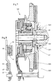
- a controllable unit drive 1 has a central screw 4 connected to the crankshaft 2 of an internal combustion engine 3.
- the central screw 4 is provided with a bushing 5 with a clamping roller freewheel for a sun gear 6, which also engages in a planetary gear 9 which meshes with a gear ring gear 7 of a variable pulley 8, i.e. the planetary gear 9 is arranged radially between the gear ring gear 7 and the sun gear 6.
- a brake magnet 11 is connected to the sun gear 6 via an electric cable 10 connected to a power source (not shown).
- variable pulley 8 which is rolled from sheet metal and has several pulleys, has an axial ring collar 15 which extends in the direction of the crankshaft 2 and is designed as a gear ring gear 7 at its end facing the crankshaft 2 and is provided with an internal ring gear 16 for this purpose .
- the internal ring gear 16 meshes with the planetary gear 9, which in turn engages in the sun gear 6 mounted on the bushing 5 with a bearing 17; the clamping roller freewheel 18 of the bushing 5 is only shown schematically and can be designed, for example, as a ratchet wheel with clamping ramps and clamping rollers.
- a roller bearing 19 is arranged, which is inserted there in the ring collar 15 of the belt wheel 8 and, due to its installation position and its diameter, provides a support width 20 which provides the entire axial length of the Bearing worn pulley 8 with ring collar 15 is detected.
- a second bearing which would require additional axial space, can thus be dispensed with.
- the brake magnet 11 is fastened to a support arm 21 which at the same time takes over the guiding of the electric cable 10 which supplies the magnet 11 with current.
- the support arm 21 is inserted with an eyelet 22 onto a bolt 24 fastened in the engine block 23 of the internal combustion engine and is thus prevented from rotating due to the torques occurring.
- the brake magnet 11 is carried by a deep groove ball bearing 25 arranged on the sleeve 5, with a portion of the outer jacket of the sleeve 5 as an inner ring 26 is formed for the balls of the ball bearing 25.
- the radially inner deep groove ball bearing 25 and the radially outer eyelet 22 are at a distance from one another, but are arranged in alignment, ie the eyelet 22 lies exactly below the raceway or the inner ring 26 of the single row deep groove ball bearing 25 In this way, with a torque acting on the support arm 21, a force application plane 27 runs through the eyelet 22 and the deep groove ball bearing 25; thus no tilting forces can act on the deep groove ball bearing 25, so that a second ball bearing can be dispensed with.
- a vibration damper 28 rotating at the speed of the crankshaft 2 is fastened to the planet carrier flange 13 and projects over the ring collar 15 in the direction of the variable pulley 8 with a second pulley 29 rotating like the vibration damper 28 at the speed of the crankshaft 2.
- the variable, first pulley 8 and the second pulley 29 are axially next to each other in a confined space.
- the switched, energized brake magnet 11 exerts a braking force on a brake disk 30, which fixes the sun gear 6.
- the planetary gear 109 which consists of the gear ring gear 107 formed by the axial ring collar 115 of the variable belt wheel 108, the planet gears 109a and the sun gear 106, to the side next to which the entire axial length of the aggregate drive 101 supporting roller bearings 119.
- the variable pulley 108 compared to the unit drive shown in FIG. 2, axially displaced in the direction of the engine block 123 and arranged radially above the roller bearing 119, which results in a central belt tension and a smaller axial width of the unit drive 101.
- Such a central belt tension is also present in the unit drive 201 shown in FIG.
- a material pairing that is both technically favorable and advantageous for the operation of the unit drive 301 is present if - as shown in FIG. 5 - the internal ring gear 316, i.e. the teeth of the internal gear 307 and the teeth 306a of the sun gear 306 are made of plastic, while the planet gears 309a of the planetary gear 309 are made of steel.
- the outer ring 319a of the roller bearing 319 forms the gear ring gear 307, so that steel is available as a carrier material for the inner ring gear 316 encapsulated with plastic.
- the sun gear 306 and its plastic-coated teeth 306a are an integral part of the pinch roller freewheel 318 of the bushing 305.
- a gear ring gear 307a made entirely of plastic is shown in the lower half of FIG.
- the all-plastic gear ring gear 307a is either included the ring collar 315 of the variable belt wheel 308 or firmly anchored to the outer ring 319a of the roller bearing 319, preferably connected in one piece, depending on whether the ring collar 315 or the outer ring 319a of the roller bearing 319 is designed as a sleeve for the gear ring gear 307a; 5 shows both alternatives.
- the ring collar 315 or the outer ring 319a is provided with openings 54; the outer surface of the ring collar 315 or of the outer ring 319a has grooves 55, so that the injected plastic penetrates the openings 54, is distributed in the grooves 55 and can form an intimate connection with the carrier material (sleeve).
- annular space 56 is arranged in the vibration damper 428 according to FIG. 6, which can optionally have several stores.
- lubricating grease reaches the gearwheels of the planetary gear 409 via one or more connecting grooves 58 when the unit drive 401 is at a standstill; during operation, however, the grease is pressed back into the annular space 56 via the connecting grooves 58 due to centrifugal force.
- lubricating oil can be conducted into the interior of the planetary gear 409 and stored in the annular space 56 during operation; the oil is supplied via an oil inflow channel 59 running from the engine block 423 through the central screw 404 carrying the unit drive 401. Excess oil is returned via an oil discharge channel 60.
- the lubricating oil is metered by means of a nozzle 61 arranged in the oil inflow channel 59 and is supplied only once per cycle.
- FIG. 7 shows an aggregate unit 501, the axial size of which can be varied as desired by means of an exchange hub 62. It is no longer the planet carrier flange 513 that is supported by a hub, but the replacement hub 62, which is also welded to the vibration damper 528, on the crankshaft 502 and is thus arranged axially between the planet carrier flange 513 and the engine block 523.
- the planet carrier flange 513 lies flat against the exchange hub 62 and as a pressure piece, so that there is a clamping connection in which the torque is transmitted by friction from the crankshaft 502 to the unit drive 501.
- the dimensions of the unit drive 501 can be variably adapted to different installation conditions; only a correspondingly thicker or thinner replacement hub 62 needs to be installed.
- variable torque support arm shown in FIG. 8, which consists of a steel cover 66 that closes the magnetic pot 64 of the brake magnet 11 and is provided with a tab 65 and one assigned to the tab 65 Mating connector 67 is composed.
- a cover with a correspondingly longer or shorter tab 65 or the mating connector 67 fastened to the engine block by means of the eyelet 22 needs to be exchanged for a longer or shorter mating connector. Since this variably adjustable torque support arm is a plug connection, assembly and disassembly is very easy.
- the drive does not take place via the crankshaft of the internal combustion engine, but via a driven belt wheel 68, which is adjacent to the variable belt wheel 608 arranged laterally next to the roller bearing 619.
- the roller bearing 619 - as in the embodiment according to FIG. 2 - is arranged axially between the variable belt wheel 608 and the planetary gear 609.
- the unit drive 601 is carried by an axis 69 of a flange 71 fastened to the engine block 623 by means of screws 70.
- the support shaft 69 provided with needle bearings 72 protrudes into the bore of the central bushing 605.
- the compact design of the unit drive 601 is achieved by flange-mounting on the engine block 623 or on a bracket (not shown) attached to the engine block. Otherwise, the same components are used in this unit drive as in the drives described above, so that a highly adaptable modular system can be implemented in all described unit drives.
- a control by means of an electronic control unit 31 is shown as an example for the unit drive 1 according to FIG. 2 - to be used equally for the other described unit drives.
- An on-board electrical system 33 supplying a wide variety of consumers 32 is connected to both a three-phase generator 34 and an accumulator 35.
- the generator 34 like a hydraulic pump 36, an air conditioning compressor 37 and a cooling water pump 38 with a motor fan 39, can be driven at a higher speed by means of the pulley 8, that is, connected to the unit drive 1.
- the air conditioning compressor 37 which is not constantly required, is connected to the unit drive 1 by means of a magnetic coupling 40.
- the electronic control unit 31 has, as integrated components, a demand control 41, an air conditioning control 42 and a drive-up control 43.
- the demand control 41 is connected to a temperature sensor 48 via a control line 44 with a current sensor 45 arranged on the accumulator 35, the drive control 43 via control lines 46 and 47 of the brake magnet or a speed sensor 49 of the unit drive 1 and the air conditioning control 42 are connected via a control line 50 to the magnetic coupling 40 of the air conditioning compressor 37.
- Both the demand control 41 and the air conditioning control 42 in which a plurality of speed inputs, not symbolized by arrows 51, are evaluated, which can be, for example, the hydraulic pump 36 and the cooling water pump 38 with a motor fan 39, are connected to control lines 52, 53 connected to the high drive control 43. Due to the interconnected controls 41, 42, 43, the electronic control unit 31 offers flexible intervention options for determining the switching speed triggering the activation of the high drive via the variable belt wheel 8.
- the power exchange of the accumulator 35 with the vehicle electrical system 33 or the generator 34 can be detected.
- the variable pulley 8 is driven up. Due to the speeds entered into the air conditioning control 42 via the inputs 51, the unit, according to the example, becomes the climate Compressor 37, which requires the highest speed, is given priority and the high drive of the variable pulley 7 is switched on in any case when this unit, the air conditioning compressor 37, has to be supplied with the nominal power.
- the high drive is always switched off and the drive unit 1 is switched to direct drive through the crankshaft 2, since all units to be supplied have sufficient performance at this limit engine speed.
- the temperature sensor 48 arranged in or on the brake magnet 11 brings about a safety shutdown in the event of excessive heat which arises in the event of faults due to higher temperatures.
- the brake magnet 11 is switched off, i.e. de-energized, and the units are driven in direct drive through the crankshaft 2.
- variable pulley or its axial ring collar integrated gear ring and pulley bearing an aggregate drive in a compact design, which can be installed in the engine compartment without changing the spatial arrangement of the engine or its aggregates.
- the gain in space allows the vibration damper to be included in the drive unit and, in addition to the high drive via the variable pulley, to provide a drive that continuously rotates at the crankshaft speed.
- control method by means of the electronic control unit allows flexible interventions, in particular for the speed-dependent activation of the high drive, i.e. for setting the switching speed.
Landscapes
- Engineering & Computer Science (AREA)
- Chemical & Material Sciences (AREA)
- Combustion & Propulsion (AREA)
- Mechanical Engineering (AREA)
- General Engineering & Computer Science (AREA)
- Retarders (AREA)
- Devices For Conveying Motion By Means Of Endless Flexible Members (AREA)
Applications Claiming Priority (2)
| Application Number | Priority Date | Filing Date | Title |
|---|---|---|---|
| DE19883819986 DE3819986A1 (de) | 1988-06-11 | 1988-06-11 | Regelbarer antrieb und verfahren zu seiner steuerung |
| DE3819986 | 1988-06-11 |
Publications (1)
| Publication Number | Publication Date |
|---|---|
| EP0346743A2 true EP0346743A2 (fr) | 1989-12-20 |
Family
ID=6356387
Family Applications (1)
| Application Number | Title | Priority Date | Filing Date |
|---|---|---|---|
| EP19890110255 Withdrawn EP0346743A2 (fr) | 1988-06-11 | 1989-06-07 | Dispositif d'entraînement réglable et procédé pour le commander |
Country Status (2)
| Country | Link |
|---|---|
| EP (1) | EP0346743A2 (fr) |
| DE (1) | DE3819986A1 (fr) |
Cited By (10)
| Publication number | Priority date | Publication date | Assignee | Title |
|---|---|---|---|---|
| EP0599125A1 (fr) * | 1992-11-12 | 1994-06-01 | Ford-Werke Aktiengesellschaft | Propulsion d'un arbre d'équilibrage d'un moteur en V |
| EP0654620A1 (fr) * | 1993-11-18 | 1995-05-24 | Firma Carl Freudenberg | Dispositif d'entraînement de groupes auxiliaires |
| DE19728723A1 (de) * | 1997-07-04 | 1999-01-07 | Bayerische Motoren Werke Ag | Antriebsaggregat für Kraftfahrzeuge |
| WO2001047739A1 (fr) * | 1999-12-27 | 2001-07-05 | Speed Selector, Inc. | Systeme variateur de vitesse |
| WO2005071819A1 (fr) * | 2004-01-13 | 2005-08-04 | The Gates Corporation | Transmission a deux vitesses et systeme d'entrainement par courroie |
| DE102006060872A1 (de) * | 2006-12-22 | 2008-06-26 | Dr.Ing.H.C. F. Porsche Ag | Hybrid-Antrieb für ein Kraftfahrzeug |
| US7758465B2 (en) | 2007-06-04 | 2010-07-20 | The Gates Corporation | Damped planetary transmission |
| WO2012000487A1 (fr) * | 2010-06-29 | 2012-01-05 | Schaeffler Technologies Gmbh & Co. Kg | Poulie de vilebrequin |
| WO2012130196A1 (fr) * | 2011-03-28 | 2012-10-04 | Schaeffler Technologies AG & Co. KG | Poulie à courroie de vilebrequin |
| WO2012000474A3 (fr) * | 2010-06-29 | 2013-03-28 | Schaeffler Technologies AG & Co. KG | Poulie de vilebrequin |
Families Citing this family (6)
| Publication number | Priority date | Publication date | Assignee | Title |
|---|---|---|---|---|
| US5358456A (en) * | 1991-06-07 | 1994-10-25 | Fichtel & Sachs Ag | Gear unit for combination with an auxiliary power consuming unit of a motor-vehicle |
| US5330393A (en) * | 1991-06-07 | 1994-07-19 | Fichtel & Sachs Ag | Gear unit for combination with an auxiliary power consuming unit of a motor-vehicle |
| DE19623525A1 (de) * | 1996-06-13 | 1997-12-18 | Schaeffler Waelzlager Kg | Hochtrieb für Nebenaggregate eines Riementriebs |
| DE10161700A1 (de) * | 2001-12-15 | 2003-06-18 | Bayerische Motoren Werke Ag | Variabler Riemenhochtrieb für Nebenaggregate |
| DE102008033177A1 (de) * | 2008-07-15 | 2010-01-21 | Volkswagen Ag | Regelbarer Kompressor |
| DE102012105301A1 (de) * | 2012-06-19 | 2013-12-19 | C & S Sonderfahrzeuge GmbH | Nebenaggregat zur Ansteuerung von einem oder mehreren hydraulischen Antrieben |
-
1988
- 1988-06-11 DE DE19883819986 patent/DE3819986A1/de not_active Withdrawn
-
1989
- 1989-06-07 EP EP19890110255 patent/EP0346743A2/fr not_active Withdrawn
Cited By (16)
| Publication number | Priority date | Publication date | Assignee | Title |
|---|---|---|---|---|
| EP0599125A1 (fr) * | 1992-11-12 | 1994-06-01 | Ford-Werke Aktiengesellschaft | Propulsion d'un arbre d'équilibrage d'un moteur en V |
| EP0654620A1 (fr) * | 1993-11-18 | 1995-05-24 | Firma Carl Freudenberg | Dispositif d'entraînement de groupes auxiliaires |
| DE19728723A1 (de) * | 1997-07-04 | 1999-01-07 | Bayerische Motoren Werke Ag | Antriebsaggregat für Kraftfahrzeuge |
| WO2001047739A1 (fr) * | 1999-12-27 | 2001-07-05 | Speed Selector, Inc. | Systeme variateur de vitesse |
| CN100471714C (zh) * | 2004-01-13 | 2009-03-25 | 盖茨公司 | 两档变速器和带传动系统 |
| JP2007518037A (ja) * | 2004-01-13 | 2007-07-05 | ザ ゲイツ コーポレイション | ツースピードトランスミッション及びベルトドライブシステム |
| KR100805178B1 (ko) | 2004-01-13 | 2008-02-21 | 더 게이츠 코포레이션 | 2단 변속 트랜스미션 및 벨트 구동 시스템 |
| WO2005071819A1 (fr) * | 2004-01-13 | 2005-08-04 | The Gates Corporation | Transmission a deux vitesses et systeme d'entrainement par courroie |
| AU2004314557B2 (en) * | 2004-01-13 | 2009-09-10 | The Gates Corporation | Two speed transmission and belt drive system |
| US7727115B2 (en) | 2004-01-13 | 2010-06-01 | The Gates Corporation | Two speed transmission and belt drive system |
| DE102006060872A1 (de) * | 2006-12-22 | 2008-06-26 | Dr.Ing.H.C. F. Porsche Ag | Hybrid-Antrieb für ein Kraftfahrzeug |
| US7882910B2 (en) | 2006-12-22 | 2011-02-08 | Dr. Ing. H.C.F. Porsche Aktiengesellschaft | Hybrid drive for a motor vehicle |
| US7758465B2 (en) | 2007-06-04 | 2010-07-20 | The Gates Corporation | Damped planetary transmission |
| WO2012000487A1 (fr) * | 2010-06-29 | 2012-01-05 | Schaeffler Technologies Gmbh & Co. Kg | Poulie de vilebrequin |
| WO2012000474A3 (fr) * | 2010-06-29 | 2013-03-28 | Schaeffler Technologies AG & Co. KG | Poulie de vilebrequin |
| WO2012130196A1 (fr) * | 2011-03-28 | 2012-10-04 | Schaeffler Technologies AG & Co. KG | Poulie à courroie de vilebrequin |
Also Published As
| Publication number | Publication date |
|---|---|
| DE3819986A1 (de) | 1989-12-14 |
Similar Documents
| Publication | Publication Date | Title |
|---|---|---|
| EP0346743A2 (fr) | Dispositif d'entraînement réglable et procédé pour le commander | |
| DE60127364T2 (de) | Antriebsvorrichtung | |
| DE60014291T2 (de) | Motor-/Generatorgerät für ein Kraftfahrzeug | |
| DE10160466C1 (de) | Kraftfahrzeug-Antriebseinrichtung | |
| DE112010005824B4 (de) | Steuervorrichtung für ein Fahrzeug | |
| DE102008045202B4 (de) | Koaxialstarter für eine Brennkraftmaschine | |
| DE4118729A1 (de) | Vorrichtung zum schmieren eines fahrzeugmotors | |
| DE102004050137B4 (de) | Ölzufuhrvorrichtung | |
| DE60314703T2 (de) | Kraftfahrzeug-Antriebssystem | |
| DE69218975T2 (de) | Vorrichtung zur anpassung der drehzahl einer hilfsmaschine an die eines kfz-verbrennungsmotors | |
| DE102010047507A1 (de) | Ölgekühlter Motor/Generator für einen Kraftfahrzeugantriebsstrang | |
| DE2251220A1 (de) | Drehzahlveraenderlicher elektrischer antrieb | |
| DE2349945A1 (de) | Antrieb fuer den kuehlventilator eines kraftfahrzeugmotors | |
| DE112011100712T5 (de) | Antriebsvorrichtung für ein fahrzeug | |
| DE10049197A1 (de) | Hybridfahrzeug | |
| WO2016087101A1 (fr) | Unité d'entraînement électrique, système d'entraînement hybride et véhicule | |
| DE102021103667B4 (de) | Elektrisch betreibbarer Antriebsstrang | |
| DE102009033633A1 (de) | Generator-Antriebssystem für eine Brennkraftmaschine | |
| EP1556634A1 (fr) | Dispositif d'entrainement de vehicule a moteur | |
| EP2349768B1 (fr) | Équipment pour la propulsion hybride | |
| WO2009067981A1 (fr) | Procédé de commande du fonctionnement d'un alternateur dans une chaîne cinématique de véhicule et chaîne cinématique de véhicule | |
| DE112009000477T5 (de) | Stufenloses Riemenantriebssystem | |
| DE10346921B4 (de) | Mittels eines Verbrennungsmotors eines Kraftfahrzeugs angetriebener Riementrieb | |
| DE19921864A1 (de) | Zweigang-Zugantriebsriemenscheibensystem | |
| DE69918906T2 (de) | Vorrichtung und Verfahren zur elektrischen Leistungserzeugung in Fahrzeugen |
Legal Events
| Date | Code | Title | Description |
|---|---|---|---|
| PUAI | Public reference made under article 153(3) epc to a published international application that has entered the european phase |
Free format text: ORIGINAL CODE: 0009012 |
|
| AK | Designated contracting states |
Kind code of ref document: A2 Designated state(s): DE FR GB IT SE |
|
| STAA | Information on the status of an ep patent application or granted ep patent |
Free format text: STATUS: THE APPLICATION HAS BEEN WITHDRAWN |
|
| RAP3 | Party data changed (applicant data changed or rights of an application transferred) |
Owner name: PIERBURG GMBH |
|
| 18W | Application withdrawn |
Withdrawal date: 19900112 |
|
| R18W | Application withdrawn (corrected) |
Effective date: 19900112 |