EP0346948A2 - Ossature constituée d'élements en forme de barre - Google Patents
Ossature constituée d'élements en forme de barre Download PDFInfo
- Publication number
- EP0346948A2 EP0346948A2 EP19890115135 EP89115135A EP0346948A2 EP 0346948 A2 EP0346948 A2 EP 0346948A2 EP 19890115135 EP19890115135 EP 19890115135 EP 89115135 A EP89115135 A EP 89115135A EP 0346948 A2 EP0346948 A2 EP 0346948A2
- Authority
- EP
- European Patent Office
- Prior art keywords
- core part
- framework according
- axes
- polygonal
- shaped elements
- Prior art date
- Legal status (The legal status is an assumption and is not a legal conclusion. Google has not performed a legal analysis and makes no representation as to the accuracy of the status listed.)
- Granted
Links
Images


Classifications
-
- F—MECHANICAL ENGINEERING; LIGHTING; HEATING; WEAPONS; BLASTING
- F16—ENGINEERING ELEMENTS AND UNITS; GENERAL MEASURES FOR PRODUCING AND MAINTAINING EFFECTIVE FUNCTIONING OF MACHINES OR INSTALLATIONS; THERMAL INSULATION IN GENERAL
- F16B—DEVICES FOR FASTENING OR SECURING CONSTRUCTIONAL ELEMENTS OR MACHINE PARTS TOGETHER, e.g. NAILS, BOLTS, CIRCLIPS, CLAMPS, CLIPS OR WEDGES; JOINTS OR JOINTING
- F16B7/00—Connections of rods or tubes, e.g. of non-circular section, mutually, including resilient connections
- F16B7/04—Clamping or clipping connections
- F16B7/044—Clamping or clipping connections for rods or tubes being in angled relationship
- F16B7/0446—Clamping or clipping connections for rods or tubes being in angled relationship for tubes using the innerside thereof
-
- E—FIXED CONSTRUCTIONS
- E04—BUILDING
- E04B—GENERAL BUILDING CONSTRUCTIONS; WALLS, e.g. PARTITIONS; ROOFS; FLOORS; CEILINGS; INSULATION OR OTHER PROTECTION OF BUILDINGS
- E04B1/00—Constructions in general; Structures which are not restricted either to walls, e.g. partitions, or floors or ceilings or roofs
- E04B1/343—Structures characterised by movable, separable, or collapsible parts, e.g. for transport
- E04B1/344—Structures characterised by movable, separable, or collapsible parts, e.g. for transport with hinged parts
- E04B1/3441—Structures characterised by movable, separable, or collapsible parts, e.g. for transport with hinged parts with articulated bar-shaped elements
-
- F—MECHANICAL ENGINEERING; LIGHTING; HEATING; WEAPONS; BLASTING
- F16—ENGINEERING ELEMENTS AND UNITS; GENERAL MEASURES FOR PRODUCING AND MAINTAINING EFFECTIVE FUNCTIONING OF MACHINES OR INSTALLATIONS; THERMAL INSULATION IN GENERAL
- F16B—DEVICES FOR FASTENING OR SECURING CONSTRUCTIONAL ELEMENTS OR MACHINE PARTS TOGETHER, e.g. NAILS, BOLTS, CIRCLIPS, CLAMPS, CLIPS OR WEDGES; JOINTS OR JOINTING
- F16B5/00—Joining sheets or plates, e.g. panels, to one another or to strips or bars parallel to them
- F16B5/06—Joining sheets or plates, e.g. panels, to one another or to strips or bars parallel to them by means of clamps or clips
- F16B5/0685—Joining sheets or plates to strips or bars
-
- Y—GENERAL TAGGING OF NEW TECHNOLOGICAL DEVELOPMENTS; GENERAL TAGGING OF CROSS-SECTIONAL TECHNOLOGIES SPANNING OVER SEVERAL SECTIONS OF THE IPC; TECHNICAL SUBJECTS COVERED BY FORMER USPC CROSS-REFERENCE ART COLLECTIONS [XRACs] AND DIGESTS
- Y10—TECHNICAL SUBJECTS COVERED BY FORMER USPC
- Y10T—TECHNICAL SUBJECTS COVERED BY FORMER US CLASSIFICATION
- Y10T403/00—Joints and connections
- Y10T403/55—Member ends joined by inserted section
- Y10T403/557—Expansible section
Definitions
- the invention relates to a skeleton consisting of rod-shaped elements according to the preamble of claim 1.
- Such skeletons enable the rapid construction of a spatial structure for a wide variety of purposes.
- Generically comparable skeletons have become known, for example, from US-A-4,290,244 or WO-A-84/01094.
- the connecting elements are firmly bumped into the ends of the rod-shaped elements, a plurality of connecting elements in each case being articulated at a node.
- the connecting elements have no actual gripping devices, but are provided with transverse pins which are enclosed in the two-part core parts.
- a disadvantage of these constructions is in particular that only a very specific structure can be built at a time. Modifications or the attachment or omission of individual elements are not possible for the user, since the individual components of the framework are firmly connected to one another. Removing a single part of the forest would also make the entire structure unstable.
- Connecting elements with gripping devices are known from DE-A-20 24 508 or from DE-A-22 51 228 the. In both cases, however, no core parts are provided for the formation of a knot.
- the skeleton should also allow modifications to existing structures, so that the user is not dependent on specialists if he wants to make structural changes on site at short notice.
- the axes are preferably round or polygonal in cross-section, the gripping devices gripping the axes in a form-fitting manner.
- the gripping devices gripping the axes in a form-fitting manner.
- the core part can be designed as a polyhedron or as a flat body, the axes of which lie in one plane.
- the function of the gripping device is particularly efficient if the connecting elements are designed to be divided in the plane of the tube axis and if the gripping device consists of two half-shells.
- the half-shells can be hollow-cylindrical or with a polygonal cross-section for gripping an axis.
- the two half-shells can be closed about an axis of the core part, so that an articulated or non-rotatable connection is created, which can however be released at any time.
- the core part is approximately square and has two axial sections on each side, each of which can accommodate a gripping device, two rods can be connected on one side. This facilitates the construction of three-dimensional structures and the construction of foldable structures with crossing bars.
- the width of the axle sections on the sides of the core part corresponds to the width of a gripping device, a stable connection is ensured.
- the core part is divided into two halves that can be joined or plugged together and have identical shapes, which are provided on the inside with diametrically opposed pins and bores.
- the core parts can also have holes in the center and / or at the corners for connecting elements, such as screws, push buttons or other axis elements.
- Two connecting elements can be joined together in a rotationally fixed manner if one has a polygonal depression and the other has a polygonal flange which fits into the depression in a form-fitting manner.
- Two core parts can also be connected at a distance from one another with a spacer tube.
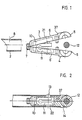
- a typical connecting element 4 consists of the two halves 6 and 6 ', which are preferably absolutely identical.
- the connecting elements are preferably made of plastic material by injection molding.
- the two halves 6 and 6 ' are put together on a locking device 7 so that they can be opened and closed like a hinge.
- a recess 10 is provided in the shaft 3 of the connecting element, which merges into an opening 21 at one point.
- the recess 10 serves to receive the spring element 11, which in the present exemplary embodiment is designed as a U-shaped bracket.
- Each spring element carries a cam 13 which projects from the opening 21 in the closed state.
- a positioning cam 22 is arranged on the lower leg of the U-shaped bracket, but only partially penetrates the opening 21 and is used only for positioning the spring element 11.
- Each connecting element is provided with a gripping device 14, which in the present case consists of the two half-shells 5 and 5 '. These two half-shells are designed so that they can grip an axis 12 in a form-fitting manner.
- a circumferential shoulder 37 delimits the shaft 3, the shoulder preferably having a height which corresponds approximately to the wall thickness of the tubes.
- the rod-shaped element 2 is to be connected with its tubular end to the axis 12.
- the tubular element 2 is provided with an opening 8, the diameter of which is somewhat larger than the diameter of the Nockens 13.
- the connecting element is now opened so far that the two half-shells 5 and 5 'can take the axis 12.
- the connecting element is then closed, the cam 13 protruding from the opening 21.
- the shaft 3 of the closed connecting element is then pushed into the element 2.
- the cam 13 is pressed inwards until it reaches the opening 8, where it engages due to the spring action, as shown in FIG. 2.
- the cam 13 To remove the connecting element from the element 2, the cam 13 must be pressed inward again so that the lock is released. This can be done in the simplest way by hand or with the aid of a screwdriver or the like.
- the axis 12 or the half-shells 5 could also e.g. have a hexagonal or quadrangular cross section, so that it would not be possible to rotate the axis when the connecting element is closed.
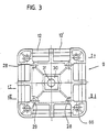
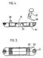
- Figures 3 to 5 show a core part 9 in the form of a square, flat body, to which several rod-shaped elements can be connected.
- this part is also divided into two halves, which are of identical shape and can be inserted into one another, as shown in particular in FIG. 5.
- diametrically opposite pins 28 and bores 29 are provided on the inside.
- a depression 30 is provided in the center, which, for example, can accommodate a hexagonal body in a rotationally fixed manner.
- the through hole 31 and the holes 66 are used for took a screw to connect the core part with other components.
- a push button 67 could also be used, the two resilient lugs 68 of which can be pressed together.
- the same push button could also be inserted through the closed half-shells of a connecting element.
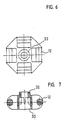
- FIGS. 6 and 7 Another type of core part is shown in FIGS. 6 and 7, which is somewhat smaller and has only a single axle section 12 on each side.
- a hexagon flange 32 is arranged on one side, which fits positively into the recess 30 of the core part according to FIG. 3.
- the recess 33 serves to receive a screw head or the flange of an adjacent core part.
- FIG. 8 shows the combination of two core parts according to FIGS. 3 and 6.
- the small core part 63 is inserted into the large core part 64, the hexagonal flange 32 penetrating into the depression 30.
- the two parts 63 and 64 are non-positively connected to one another with a fastening screw, not shown.
- the core parts can also have other configurations and can, for example, be hexagonal, triangular or also formed as a polyhedron.
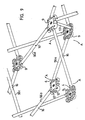
- FIGS. 9 and 10 framework structures 1 are described, which represent a flat spatial structure.
- Individual pairs of rods or scissors 56 are connected to one another to form closed units with a polygonal grid.
- Such a closed unit consisting of the four scissors 56a, 56b, 56c and 56d, is shown in FIG.
- the ends of the scissors 56 are articulated to one another by means of the large core parts 9.
- the individual tubes of the scissors 56 are offset from one another by a tube thickness, a connection to an axle section 12 or 12 'is alternately required.
- Each closed unit can be folded into a structure in which all the rods of the individual scissors 56 run almost parallel to one another and are close to one another.
- Each individual pair of scissors performs a pivoting movement around the intersection 16, as indicated by the direction of arrow A.
- the rod-shaped elements 2 are connected to one another in an articulated manner by means of screws or the like.
- two core parts 9 are connected to a spacer tube 57.
- This can, as in FIG. 9, be connected to the axes 12 or, as shown in FIG. 10, in the center of the core parts 9.
- the spacer tube can be provided on both sides with the push button already mentioned.
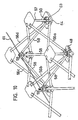
- FIG. 10 again shows a closed unit consisting of four scissors 56a, 56b, 56c and 56d connected to one another, as has already been shown in FIG.
- the closed unit is reinforced with a pyramid-like rod structure, each rod 58 of this rod structure being connected to a connection point between two scissors.
- the connection point is constructed approximately according to FIG. 8 and consists of a small core part 63 which is fastened on a large core part 64.
- the pyramid rods 58 meet at the pyramid tip 59 and are connected there to form a node, as is shown, for example, in FIG. 11.
- another closed unit with a pyramid tip 59 ' is partially shown on the left side.
- the pyramid-like rod structures serve to reinforce the closed units in the horizontal plane, so that for example, ceiling structures can be built.
- the adjacent pyramid tips 59, 59 ', etc. are preferably connected to one another via a cable 61. Instead of the cable, another rod or surface can of course be used.
- the cable pull has the advantage that the entire frame can be folded up, the cable pull hanging loosely in the folded-up state.
- the length of the pyramid rods 58 must be selected such that they do not hinder the folding of the scissors 56.
- the pyramid tips on a ceiling construction can be directed either upwards or downwards or in both directions. The sag of a ceiling construction can be corrected with the cable 61.
- the pyramid tips also create a further connection level, on which additional structures can be built using core parts.
- FIG. 11 shows a pyramid tip, the small core part 63 being provided with a cable pull holder 62. A cable can be pulled into this and clamped with a locking screw 60.
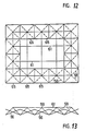
- FIGS. 12 and 13 show a construction with a horizontal extension consisting of a plurality of closed units 65 arranged in a row.
- the pyramid rods 58 are shown as broken lines.
- the cables 61 connect the neighboring pyramid tips in a straight line.
- dome-like structures can also be erected, e.g. can be used as emergency accommodation with suitable covering.
Landscapes
- Engineering & Computer Science (AREA)
- General Engineering & Computer Science (AREA)
- Mechanical Engineering (AREA)
- Architecture (AREA)
- Physics & Mathematics (AREA)
- Electromagnetism (AREA)
- Civil Engineering (AREA)
- Structural Engineering (AREA)
- Mutual Connection Of Rods And Tubes (AREA)
- Joining Of Building Structures In Genera (AREA)
- Superconductors And Manufacturing Methods Therefor (AREA)
- Assembled Shelves (AREA)
- Variable-Direction Aerials And Aerial Arrays (AREA)
- Prostheses (AREA)
- Grates (AREA)
- Rod-Shaped Construction Members (AREA)
- Pit Excavations, Shoring, Fill Or Stabilisation Of Slopes (AREA)
- Manufacturing Of Tubular Articles Or Embedded Moulded Articles (AREA)
Priority Applications (1)
| Application Number | Priority Date | Filing Date | Title |
|---|---|---|---|
| AT89115135T ATE100166T1 (de) | 1985-12-02 | 1989-08-17 | Gerippe bestehend aus stabfoermigen elementen. |
Applications Claiming Priority (2)
| Application Number | Priority Date | Filing Date | Title |
|---|---|---|---|
| CH5152/85 | 1985-12-02 | ||
| CH515285 | 1985-12-02 |
Related Parent Applications (1)
| Application Number | Title | Priority Date | Filing Date |
|---|---|---|---|
| EP86906748.8 Division | 1987-06-10 |
Publications (3)
| Publication Number | Publication Date |
|---|---|
| EP0346948A2 true EP0346948A2 (fr) | 1989-12-20 |
| EP0346948A3 EP0346948A3 (en) | 1990-05-09 |
| EP0346948B1 EP0346948B1 (fr) | 1994-01-12 |
Family
ID=4288806
Family Applications (2)
| Application Number | Title | Priority Date | Filing Date |
|---|---|---|---|
| EP86906748A Expired - Lifetime EP0249601B1 (fr) | 1985-12-02 | 1986-11-25 | Ossature constituee d'elements en forme de barre |
| EP89115135A Expired - Lifetime EP0346948B1 (fr) | 1985-12-02 | 1986-11-25 | Ossature constituée d'élements en forme de barre |
Family Applications Before (1)
| Application Number | Title | Priority Date | Filing Date |
|---|---|---|---|
| EP86906748A Expired - Lifetime EP0249601B1 (fr) | 1985-12-02 | 1986-11-25 | Ossature constituee d'elements en forme de barre |
Country Status (9)
| Country | Link |
|---|---|
| US (1) | US4829735A (fr) |
| EP (2) | EP0249601B1 (fr) |
| JP (1) | JPH0723626B2 (fr) |
| AT (1) | ATE100166T1 (fr) |
| AU (1) | AU585676B2 (fr) |
| CA (1) | CA1290546C (fr) |
| DE (2) | DE3689546D1 (fr) |
| ES (1) | ES2003954A6 (fr) |
| WO (1) | WO1987003346A1 (fr) |
Cited By (1)
| Publication number | Priority date | Publication date | Assignee | Title |
|---|---|---|---|---|
| DE4203838A1 (de) * | 1992-02-10 | 1993-08-12 | Markus Jehs | Traggeruest in gitterbauweise, insb. fuer ausstellungen und veranstaltungen |
Families Citing this family (17)
| Publication number | Priority date | Publication date | Assignee | Title |
|---|---|---|---|---|
| DE3731184A1 (de) * | 1987-09-17 | 1989-03-30 | Elmar Wolf | Gitterwerk aus staeben und knoten sowie dessen herstellung |
| IT1213606B (it) * | 1987-09-18 | 1989-12-29 | Quattrocchio Srl | Dispositivo di giunzione e collegamento particolarmente per strutture modulari a traliccio |
| DE3868822D1 (de) * | 1987-09-29 | 1992-04-09 | Lanz Oensingen Ag | Variable montagerahmen-anordnung. |
| SE8801224D0 (sv) * | 1988-04-05 | 1988-04-05 | Curth Danielsson | Kopplingsanordning samt sett for dess framstellning |
| US5161344A (en) * | 1990-01-15 | 1992-11-10 | Expand International Ab | Portable display structure |
| US5491991A (en) * | 1993-07-08 | 1996-02-20 | Guillory; Samuel L. | Security device for an automobile |
| DE9417425U1 (de) * | 1994-10-31 | 1995-01-19 | Rosing, Adolf, 93047 Regensburg | Verbindungselement für rohrförmige Gegenstände |
| US5943837A (en) * | 1996-01-30 | 1999-08-31 | Tvi Corporation | Quick erect shelter apparatus |
| WO1999006985A1 (fr) | 1997-07-29 | 1999-02-11 | Intex Exhibits International, L.L.C. | Systeme d'affichage portable |
| US6244011B1 (en) | 1998-09-21 | 2001-06-12 | Tvi Corporation | Inverted V-shaped display framework |
| US20040188667A1 (en) * | 2002-01-12 | 2004-09-30 | Spur Innovation, Inc. | Portable collapsible corral fence |
| US20030213513A1 (en) * | 2002-05-17 | 2003-11-20 | Eriksen Steen Mandsfelt | Expandable framework structure for a canopy |
| JP5123566B2 (ja) * | 2007-05-25 | 2013-01-23 | 株式会社 コーゲイ | 折り畳みパイプ棚用管継手 |
| CN102537194B (zh) * | 2011-11-11 | 2013-10-30 | 江苏科技大学 | 一种用于外螺纹轴杆的快速连接装置 |
| DE102016002899B4 (de) | 2016-03-09 | 2020-03-12 | Johannes Kraus | Feuerraum mit verbessertem Ausbrand |
| US10753119B2 (en) | 2017-03-14 | 2020-08-25 | S & S Structures, Inc. | Portable structure with solar shade |
| US11142906B2 (en) * | 2018-07-06 | 2021-10-12 | Creative Tent International, Llc | Semi-permanent relocatable structure system |
Family Cites Families (15)
| Publication number | Priority date | Publication date | Assignee | Title |
|---|---|---|---|---|
| US1322801A (en) * | 1919-11-25 | lewis | ||
| US2762639A (en) * | 1953-01-07 | 1956-09-11 | Molter Ralph Marcy | Joint connections for framing systems |
| US2941294A (en) * | 1958-06-18 | 1960-06-21 | Peter S Vosbikian | Handles for manual tools with means to interlock with the shank of a working tool |
| FR1418868A (fr) * | 1964-07-03 | 1965-11-26 | Vallourec | Dispositif d'assemblage de tubes ou organes analogues |
| DE2024508A1 (de) * | 1970-05-20 | 1971-12-16 | Hanning Kunststoffe R Hanning | Rohrverbindungssystem |
| FR2251228A5 (en) * | 1973-11-14 | 1975-06-06 | Barrellon Pierre | Device for joining tubes of of tubular framework - arms on split ring around tube are pressed together and into second tube |
| FR2331745A1 (fr) * | 1975-11-14 | 1977-06-10 | Vuarnesson Bernard | Noeud d'assemblage polyedrique |
| US4290244A (en) * | 1976-07-13 | 1981-09-22 | Zeigler Theodore Richard | Collapsible self-supporting structures and panels and hub therefor |
| DE7820267U1 (de) * | 1978-07-06 | 1979-02-15 | Ruether, Hubert, Dipl.-Ing., 2105 Seevetal | Steckverbinder mit Verbindungsrohr und einer gesicherten, lösbaren Steckverbindung beider |
| EP0080556B1 (fr) * | 1981-11-26 | 1986-10-22 | Hestex Systems B.V. | Serrure enfichable à serrage pour l'assemblage amovible de deux éléments de construction |
| US4522008A (en) * | 1982-08-19 | 1985-06-11 | Zeigler Theodore Richard | Clip for self-locking collapsible/expandable structures |
| DE3369245D1 (en) * | 1982-09-24 | 1987-02-26 | Preben Nodskov | A collapsible exhibit panel |
| GB8330122D0 (en) * | 1983-11-11 | 1983-12-21 | Stephenson C J S | Connector for framework structure |
| FR2563293B1 (fr) * | 1984-04-18 | 1987-10-02 | Technal France | Piece de jonction pour assembler avec serrage deux profiles, notamment equerre pour assemblage d'onglet et embout pour assemblage en bout |
| US4580922A (en) * | 1984-12-17 | 1986-04-08 | General Electric Co. | Vertex fittings derived from a master fitting |
-
1986
- 1986-11-25 US US07/095,538 patent/US4829735A/en not_active Expired - Fee Related
- 1986-11-25 EP EP86906748A patent/EP0249601B1/fr not_active Expired - Lifetime
- 1986-11-25 DE DE89115135T patent/DE3689546D1/de not_active Expired - Fee Related
- 1986-11-25 AU AU66244/86A patent/AU585676B2/en not_active Ceased
- 1986-11-25 WO PCT/CH1986/000163 patent/WO1987003346A1/fr not_active Ceased
- 1986-11-25 DE DE8686906748T patent/DE3669757D1/de not_active Expired - Fee Related
- 1986-11-25 JP JP61506023A patent/JPH0723626B2/ja not_active Expired - Lifetime
- 1986-11-25 EP EP89115135A patent/EP0346948B1/fr not_active Expired - Lifetime
- 1986-11-28 CA CA000524142A patent/CA1290546C/fr not_active Expired - Lifetime
- 1986-12-01 ES ES8603257A patent/ES2003954A6/es not_active Expired
-
1989
- 1989-08-17 AT AT89115135T patent/ATE100166T1/de not_active IP Right Cessation
Cited By (1)
| Publication number | Priority date | Publication date | Assignee | Title |
|---|---|---|---|---|
| DE4203838A1 (de) * | 1992-02-10 | 1993-08-12 | Markus Jehs | Traggeruest in gitterbauweise, insb. fuer ausstellungen und veranstaltungen |
Also Published As
| Publication number | Publication date |
|---|---|
| ES2003954A6 (es) | 1988-12-01 |
| JPH0723626B2 (ja) | 1995-03-15 |
| EP0249601A1 (fr) | 1987-12-23 |
| AU6624486A (en) | 1987-07-01 |
| JPS63502363A (ja) | 1988-09-08 |
| DE3689546D1 (de) | 1994-02-24 |
| DE3669757D1 (de) | 1990-04-26 |
| EP0346948B1 (fr) | 1994-01-12 |
| EP0346948A3 (en) | 1990-05-09 |
| AU585676B2 (en) | 1989-06-22 |
| WO1987003346A1 (fr) | 1987-06-04 |
| US4829735A (en) | 1989-05-16 |
| ATE100166T1 (de) | 1994-01-15 |
| CA1290546C (fr) | 1991-10-15 |
| EP0249601B1 (fr) | 1990-03-21 |
Similar Documents
| Publication | Publication Date | Title |
|---|---|---|
| EP0346948B1 (fr) | Ossature constituée d'élements en forme de barre | |
| EP0393090B1 (fr) | Jeu d'elements de construction pour charpentes de support | |
| DE3704831C2 (fr) | ||
| EP0144030A2 (fr) | Tuyau profilé pour la réalisation de contructions facilement montables et démontables | |
| DE1750969B1 (de) | Verbindungsvorrichtung zur verbindung rohrfoermiger teile | |
| EP0297033A2 (fr) | Elément de fixation pour une barre | |
| DE2815243A1 (de) | Schalentragwerk aus knotenpunktverbindungen und tragwerksstaeben sowie verfahren zur errichtung desselben | |
| EP0313925A1 (fr) | Système à noeuds et barres | |
| EP0541487B1 (fr) | Dispositif d'ancrage pour éléments de construction tendus | |
| DE3837505A1 (de) | Praesentationsgestell | |
| EP1081300A2 (fr) | Bâtiment | |
| WO1993017192A1 (fr) | Systeme de construction | |
| DE102007014263B3 (de) | Verbindungsknoten für ein zwei- oder dreimensionales Tragwerk | |
| DE2711903C3 (fr) | ||
| WO2013060470A1 (fr) | Dispositif porteur pour un dispositif meuble, en particulier pour un meuble de séparation | |
| EP0307628B1 (fr) | Structure réticulée avec barres et noeuds | |
| DE4304602C2 (de) | Verbindungsknoten | |
| DE3022439C2 (de) | Gerüst | |
| DE19953904C1 (de) | Bausatz für Gartengestaltung | |
| DE4211380A1 (de) | Bauelement zur Herstellung insbesondere von Baukörperkonturen | |
| DE3914420A1 (de) | Knoten fuer rohrkonstruktionen od. dgl. | |
| DE3942122A1 (de) | Tragkonstruktion, insbesondere fuer leicht montier- und demontierbare messebauten | |
| DE1096582B (de) | Stabfoermiges Bauelement mit Winkelquerschnitt und regelmaessigen Reihen von Durchbrechungen | |
| DE3801660C2 (de) | Knotenstück zur Verbindung der Enden von Gitterträgern | |
| DE3302859C2 (de) | Spannschloß für Schalungen, Gerüste und dgl. |
Legal Events
| Date | Code | Title | Description |
|---|---|---|---|
| PUAI | Public reference made under article 153(3) epc to a published international application that has entered the european phase |
Free format text: ORIGINAL CODE: 0009012 |
|
| AC | Divisional application: reference to earlier application |
Ref document number: 249601 Country of ref document: EP |
|
| AK | Designated contracting states |
Kind code of ref document: A2 Designated state(s): AT BE CH DE FR GB IT LI NL SE |
|
| PUAL | Search report despatched |
Free format text: ORIGINAL CODE: 0009013 |
|
| AK | Designated contracting states |
Kind code of ref document: A3 Designated state(s): AT BE CH DE FR GB IT LI NL SE |
|
| 17P | Request for examination filed |
Effective date: 19901016 |
|
| 17Q | First examination report despatched |
Effective date: 19920504 |
|
| RAP1 | Party data changed (applicant data changed or rights of an application transferred) |
Owner name: ENTWURF PARTNER RUEDI ZWISSLER |
|
| RIN1 | Information on inventor provided before grant (corrected) |
Inventor name: ZWISSLER, RUEDI |
|
| ITF | It: translation for a ep patent filed | ||
| GRAA | (expected) grant |
Free format text: ORIGINAL CODE: 0009210 |
|
| AC | Divisional application: reference to earlier application |
Ref document number: 249601 Country of ref document: EP |
|
| AK | Designated contracting states |
Kind code of ref document: B1 Designated state(s): AT BE CH DE FR GB IT LI NL SE |
|
| REF | Corresponds to: |
Ref document number: 100166 Country of ref document: AT Date of ref document: 19940115 Kind code of ref document: T |
|
| REF | Corresponds to: |
Ref document number: 3689546 Country of ref document: DE Date of ref document: 19940224 |
|
| ET | Fr: translation filed | ||
| GBT | Gb: translation of ep patent filed (gb section 77(6)(a)/1977) |
Effective date: 19940310 |
|
| PLBI | Opposition filed |
Free format text: ORIGINAL CODE: 0009260 |
|
| PGFP | Annual fee paid to national office [announced via postgrant information from national office to epo] |
Ref country code: SE Payment date: 19941024 Year of fee payment: 9 |
|
| PGFP | Annual fee paid to national office [announced via postgrant information from national office to epo] |
Ref country code: BE Payment date: 19941028 Year of fee payment: 9 |
|
| 26 | Opposition filed |
Opponent name: HERRN ELMAR WOLF Effective date: 19941011 |
|
| EAL | Se: european patent in force in sweden |
Ref document number: 89115135.9 |
|
| NLR1 | Nl: opposition has been filed with the epo |
Opponent name: HERRN ELMAR WOLF. |
|
| PG25 | Lapsed in a contracting state [announced via postgrant information from national office to epo] |
Ref country code: SE Effective date: 19951126 |
|
| PG25 | Lapsed in a contracting state [announced via postgrant information from national office to epo] |
Ref country code: BE Effective date: 19951130 |
|
| PLBO | Opposition rejected |
Free format text: ORIGINAL CODE: EPIDOS REJO |
|
| APAC | Appeal dossier modified |
Free format text: ORIGINAL CODE: EPIDOS NOAPO |
|
| APAA | Appeal reference recorded |
Free format text: ORIGINAL CODE: EPIDOS REFN |
|
| BERE | Be: lapsed |
Owner name: ENTWURF PARTNER RUEDI ZWISSLER Effective date: 19951130 |
|
| EUG | Se: european patent has lapsed |
Ref document number: 89115135.9 |
|
| APAC | Appeal dossier modified |
Free format text: ORIGINAL CODE: EPIDOS NOAPO |
|
| PLBN | Opposition rejected |
Free format text: ORIGINAL CODE: 0009273 |
|
| STAA | Information on the status of an ep patent application or granted ep patent |
Free format text: STATUS: OPPOSITION REJECTED |
|
| 27O | Opposition rejected |
Effective date: 19970303 |
|
| NLR2 | Nl: decision of opposition | ||
| REG | Reference to a national code |
Ref country code: FR Ref legal event code: TP |
|
| REG | Reference to a national code |
Ref country code: GB Ref legal event code: 732E |
|
| NLS | Nl: assignments of ep-patents |
Owner name: ORIGON PRAESENTATIONSSYSTEME GMBH |
|
| PGFP | Annual fee paid to national office [announced via postgrant information from national office to epo] |
Ref country code: GB Payment date: 19991112 Year of fee payment: 14 |
|
| PGFP | Annual fee paid to national office [announced via postgrant information from national office to epo] |
Ref country code: FR Payment date: 19991129 Year of fee payment: 14 |
|
| PGFP | Annual fee paid to national office [announced via postgrant information from national office to epo] |
Ref country code: NL Payment date: 19991130 Year of fee payment: 14 |
|
| PGFP | Annual fee paid to national office [announced via postgrant information from national office to epo] |
Ref country code: AT Payment date: 20000926 Year of fee payment: 15 |
|
| PG25 | Lapsed in a contracting state [announced via postgrant information from national office to epo] |
Ref country code: GB Free format text: LAPSE BECAUSE OF NON-PAYMENT OF DUE FEES Effective date: 20001125 |
|
| PGFP | Annual fee paid to national office [announced via postgrant information from national office to epo] |
Ref country code: CH Payment date: 20010122 Year of fee payment: 15 |
|
| PG25 | Lapsed in a contracting state [announced via postgrant information from national office to epo] |
Ref country code: NL Free format text: LAPSE BECAUSE OF NON-PAYMENT OF DUE FEES Effective date: 20010601 |
|
| GBPC | Gb: european patent ceased through non-payment of renewal fee |
Effective date: 20001125 |
|
| PG25 | Lapsed in a contracting state [announced via postgrant information from national office to epo] |
Ref country code: FR Free format text: LAPSE BECAUSE OF NON-PAYMENT OF DUE FEES Effective date: 20010731 |
|
| NLV4 | Nl: lapsed or anulled due to non-payment of the annual fee |
Effective date: 20010601 |
|
| REG | Reference to a national code |
Ref country code: FR Ref legal event code: ST |
|
| PG25 | Lapsed in a contracting state [announced via postgrant information from national office to epo] |
Ref country code: AT Free format text: LAPSE BECAUSE OF NON-PAYMENT OF DUE FEES Effective date: 20011125 |
|
| PG25 | Lapsed in a contracting state [announced via postgrant information from national office to epo] |
Ref country code: LI Free format text: LAPSE BECAUSE OF NON-PAYMENT OF DUE FEES Effective date: 20011130 Ref country code: CH Free format text: LAPSE BECAUSE OF NON-PAYMENT OF DUE FEES Effective date: 20011130 |
|
| REG | Reference to a national code |
Ref country code: CH Ref legal event code: PL |
|
| PGFP | Annual fee paid to national office [announced via postgrant information from national office to epo] |
Ref country code: DE Payment date: 20030122 Year of fee payment: 17 |
|
| PG25 | Lapsed in a contracting state [announced via postgrant information from national office to epo] |
Ref country code: DE Free format text: LAPSE BECAUSE OF NON-PAYMENT OF DUE FEES Effective date: 20040602 |
|
| APAH | Appeal reference modified |
Free format text: ORIGINAL CODE: EPIDOSCREFNO |
|
| PG25 | Lapsed in a contracting state [announced via postgrant information from national office to epo] |
Ref country code: IT Free format text: LAPSE BECAUSE OF NON-PAYMENT OF DUE FEES;WARNING: LAPSES OF ITALIAN PATENTS WITH EFFECTIVE DATE BEFORE 2007 MAY HAVE OCCURRED AT ANY TIME BEFORE 2007. THE CORRECT EFFECTIVE DATE MAY BE DIFFERENT FROM THE ONE RECORDED. Effective date: 20051125 |