EP0346974A2 - Agencement en quadrature de bobines à haute fréquence pour un appareil d'examen à résonance nucléaire - Google Patents
Agencement en quadrature de bobines à haute fréquence pour un appareil d'examen à résonance nucléaire Download PDFInfo
- Publication number
- EP0346974A2 EP0346974A2 EP89201473A EP89201473A EP0346974A2 EP 0346974 A2 EP0346974 A2 EP 0346974A2 EP 89201473 A EP89201473 A EP 89201473A EP 89201473 A EP89201473 A EP 89201473A EP 0346974 A2 EP0346974 A2 EP 0346974A2
- Authority
- EP
- European Patent Office
- Prior art keywords
- frequency
- coil
- coils
- conductor sections
- pair
- Prior art date
- Legal status (The legal status is an assumption and is not a legal conclusion. Google has not performed a legal analysis and makes no representation as to the accuracy of the status listed.)
- Withdrawn
Links
Images
Classifications
-
- G—PHYSICS
- G01—MEASURING; TESTING
- G01R—MEASURING ELECTRIC VARIABLES; MEASURING MAGNETIC VARIABLES
- G01R33/00—Arrangements or instruments for measuring magnetic variables
- G01R33/20—Arrangements or instruments for measuring magnetic variables involving magnetic resonance
- G01R33/28—Details of apparatus provided for in groups G01R33/44 - G01R33/64
- G01R33/32—Excitation or detection systems, e.g. using radio frequency signals
- G01R33/36—Electrical details, e.g. matching or coupling of the coil to the receiver
- G01R33/3678—Electrical details, e.g. matching or coupling of the coil to the receiver involving quadrature drive or detection, e.g. a circularly polarized RF magnetic field
-
- G—PHYSICS
- G01—MEASURING; TESTING
- G01R—MEASURING ELECTRIC VARIABLES; MEASURING MAGNETIC VARIABLES
- G01R33/00—Arrangements or instruments for measuring magnetic variables
- G01R33/20—Arrangements or instruments for measuring magnetic variables involving magnetic resonance
- G01R33/28—Details of apparatus provided for in groups G01R33/44 - G01R33/64
- G01R33/32—Excitation or detection systems, e.g. using radio frequency signals
- G01R33/34—Constructional details, e.g. resonators, specially adapted to MR
- G01R33/34046—Volume type coils, e.g. bird-cage coils; Quadrature bird-cage coils; Circularly polarised coils
Definitions
- the invention relates to a high-frequency quadrature coil arrangement for a nuclear magnetic resonance examination apparatus with two pairs of coils offset by 90 o , which can be connected to one another in a high-frequency receiver or a high-frequency transmitter, and which each consist of two identical coils, offset on the circumference of a cylinder by 180 o , with parallel and perpendicular to the coil axis extending conductor sections exist.
- Such a high-frequency quadrature coil arrangement is known from EP-PS 71 896.
- Coil arrangements of this type can be used as a receiving coil and / or as a transmitting coil.
- an improvement in the signal-to-noise ratio of up to 3 dB can be achieved compared to a conventional coil arrangement, and when used as a transmitting coil, circularly polarized high-frequency fields can be generated if the two coil pairs are supplied with electrical voltages offset by 90 o ; this reduces the transmission power requirement by half!
- each pair of coils is tuned resonantly and connected to the high-frequency transmitter or the high-frequency receiver; each coil of the pair of coils is therefore connected to the transmitter or the receiver.
- jacket waves can arise on the supply lines, which results in a reduction in the quality of operation.
- the object of the present invention is a Hochfre quenz quadrature coil arrangement in this regard to further develop. This object is achieved in that the two coils of each pair are tuned to the same resonance frequency and that only one of the coils of each pair of coils can be connected to the radio frequency receiver or the radio frequency transmitter.
- the invention therefore, only one of the coils of a pair of coils is connected to the high-frequency receiver or transmitter.
- a pair of resonators is formed which is capable of two vibration modes.
- the first oscillation mode the currents flow through the two coils with the same sense of rotation and in the second oscillation mode a high-frequency current flows through the two coils of a pair with the opposite sense of rotation.
- a homogeneous high-frequency field results in the interior of the coil pair, and therefore this oscillation mode of the resonator pair is used.
- the resonance frequency of this first oscillation mode lies below the natural resonance frequency of the two resonators, while the resonance frequency of the second oscillation mode lies above the natural resonance frequency.
- the two resonators must be tuned - each individually - to a natural resonance frequency that is so far above the operating frequency (that is the frequency of the high-frequency pulses generated with the coil arrangement or the nuclear magnetic resonance signals received therewith) that the Operating frequency coincides with the resonance frequency of the first vibration mode.
- the supply lines required for this can be so short and arranged that sheathed waves and a reduction in the quality of operation are avoided.
- the two pairs of coils are arranged inside or outside an insulating carrier cylinder.
- the two coil pairs are therefore at a different distance from an examination object arranged in the interior of the cylinder, so that they are thereby loaded in different ways and have different operating qualities. This disturbs the symmetry.
- a better symmetry results from the fact that the conductor sections of both coil pairs running parallel to the cylinder axis are at the same distance from the common cylinder axis.
- the conductor sections of the coil pairs which are parallel to the cylinder axis are expediently held by at least two annular supports which are perpendicular to the cylinder axis and are concentric therewith and are each provided with recesses for the conductor sections mentioned at the same distance from the cylinder axis.
- the arcuate sections of one pair of coils perpendicular to the cylinder axis are arranged inside and the other pair of coils outside the cylinder jacket defined by the conductor sections running parallel to the cylinder axis.
- the arcuate conductor sections of one pair of coils have a somewhat larger radius than that of the other, but the asymmetries between the two pairs of coils are smaller than in the known arrangement.
- the quadrature coil arrangement is rotationally symmetrical.
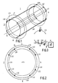
- This coil arrangement is arranged in the interior of an MRI examination device (not shown in more detail) in such a way that its axis of symmetry 5 runs in the direction of the homogeneous stationary magnetic field that is generated in such examination devices.
- the coil arrangement consists of two coil pairs 1, 2 and 3, 4 , which are offset by 90 o with respect to each other with respect to the axis of symmetry 5.
- Each coil pair in turn consists of two coils 1, 2 and 3, 4, which are arranged offset by 180 o from one another.
- Each of these four coils has two straight conductor sections L11 ... L41, L12 ... L42 running parallel to the axis of symmetry.
- These conductor sections L11 ... L41, L12 ... L42 are equidistant from the axis of symmetry 5, ie they define a cylinder jacket with axis 5 as the cylinder axis.
- the straight conductor sections are held by at least two ring-shaped carrier bodies 7, 8, the center points of which lie on the axis 5 and which are arranged perpendicular to this axis.
- the carrier bodies are made of insulating material (plastic).
- the ends of the two conductor sections belonging to a coil are connected to one another by arcuate conductor sections; for example, the ends of the conductor sections L11 and L12 belonging to the coil 1 are connected to each other by the arcuate conductor sections L13 and L14.
- These conductor sections which lie in planes perpendicular to the axis 5, describe an arc of 120 o around the axis 5 for all coils.
- the four arcuate conductor sections (L13 ... L43), which are located on one side of the coil arrangement, can therefore do not lie in the same plane at the same time and be arranged at the same distance from the axis 5.
- FIG. 3 shows the electrical connection of a pair of coils 1, 2.
- the coil 1 contains a tuning capacitor C1 in the middle of the two arcuate conductor sections L13 and L14, of which only section L13 is shown in FIG. 3.
- the coil 2, which forms a pair of coils with the coil 1 has tuning capacitors of the same size in the middle of the corresponding conductor sections.
- one of these conductor sections - section L23 in the example according to FIG. 3 - is connected to a high-frequency transmitter (or a high-frequency receiver) 6 connected, the capacitance in the middle of the conductor section being formed by several capacitors.
- two capacitors C21 and C22 are connected in series in the middle of the one arcuate conductor section (in this case L23), the common connection point of which is grounded.
- the connection of the capacitor C22 facing away from this point is connected to a high-frequency generator or a high-frequency receiver 6 via a tuning capacitor C23.
- the capacitor C23 lies above the low internal resistance (50 ohms) of the transmitter or receiver 6 practically parallel to the capacitor C22.
- the sum of the capacitances C22 and C23 therefore corresponds approximately to the capacitance C21.
- the capacitance of the capacitor C21 is also approximately twice as large as the capacitance of the capacitor C1.
- the first vibration mode-linked resonance frequency is lower (and the resonance frequency associated with the second oscillation mode is higher) than the natural resonance frequency of a resonator system, ie the frequency that results when there is no coupling with the second resonator.
- the two resonators must be tuned to a (natural resonance) frequency which is above the operating frequency required for nuclear magnetic resonance so that the resonance frequency for the first oscillation mode coincides with the operating frequency.
- the quadrature coil arrangement is to operate in a magnetic resonance scanner designed for an induction flux density of 0.5 T, the operating frequency is approximately 21.3 MHz.
- the resonance frequency for the first oscillation mode is at this operating frequency if the individual resonators are tuned to a natural resonance of approximately 21.8 MHz; the frequency of the undesired second oscillation mode would then be approximately 22.3 MHz.
- the coordination and symmetrization can be done in the following way:
- the resonator connected to the high-frequency transmitter or receiver 6 is tuned by itself to a frequency of approximately 21.8 MHz.
- the coil 1 must either not assume the position shown in FIGS. 1 and 2 or its circuit must be interrupted so that the resulting resonance frequency corresponds to the natural resonance of the coil 2. If the coil 2 is correctly tuned to the specified frequency of approximately 21.8 MHz, when this coil is supplied with this frequency, a current maximum or a current belly results in the middle of its straight conductors L21, L22. On the same There is a voltage node at the point, it therefore acts as a virtual earth point. If this point is grounded, there are therefore no changes in the electrical behavior, which can manifest itself, for example, in an unchanged display of the input reflection factor of the coil on a suitable measuring device.
- the natural resonance frequency is at the correct distance from the operating frequency and if the coil 2 is tuned to the natural resonance frequency in the manner mentioned, nothing will change in the symmetrical field distribution of the coil 2 if the resonator 1 is in the state shown in FIGS. 1 and 2 apparent position is brought and the coil 2 is fed at the operating frequency (21.3 MHz).
- the field distribution of the coil 1 can still be asymmetrical.
- a symmetrical field distribution can be achieved by varying the tuning capacitor C1 until a virtual earth point is obtained in the middle of the associated straight conductors L11 and L12. This can in turn be checked by means of a reflection factor measuring device connected to the coil 2, which determines the reflection factor at the operating frequency.
- the radio frequency field is symmetrical with respect to axis 5.
- the high-frequency magnetic field in the middle of the coil pair has the value zero or a minimum if a high-frequency current with the resonance frequency of the second oscillation mode (22.3 MHz) in the coil 2 is fed.
- the field strength in the center can be determined using a so-called pickup coil. It turns out that the minimum or zero and thus the full symmetry still has not been reached, the capacitors C1 with which the coil is tuned are changed in opposite directions until the desired minimum is reached.
- the straight conductors L11 ... L42 each consist of an 8 mm thick, 360 mm long copper tube, which is flattened at its ends in the direction of the cylinder radius, so that the distance between the arcuate conductor sections of the two coil pairs is small can be held.
- the straight conductor sections are arranged on the circumference of a cylinder with a diameter of 340 mm.
- the curved conductor pieces are formed by a 1 mm thick and 15 mm wide copper track. This results in high quality factors (approx. 650 when unloaded, approx. 220 when loaded by a patient) and small shifts in the resonance frequency when loaded by a patient of approx. 10 KHz. It is therefore not absolutely necessary to retune the resonance circuit after the patient has been introduced.
- the coupling between the two pairs of coils is low. It is less than 0.005.
- the homogeneity of the magnetic field generated with such a quadrature coil arrangement is very good; when measuring with a pick-up coil on the axis of symmetry 5, the magnetic field strength fluctuates by a maximum of + 0.5 dB. There are no jacket waves in the feed lines.
- the individual coils can also be tuned with only one capacitor or with four capacitors, which must also be arranged symmetrically.
- this must also be arranged in the middle of an arcuate conductor section, while when using four capacitors for tuning purposes
- Capacitors are expediently arranged at the four corner points of the coil, so that they connect the end of a straight conductor section (for example L11) with the end of an arcuate section (for example L13).
- the use of more capacitors (with larger capacitance) results in a smaller shift in the resonance frequency when the patient is inserted; however, the effort increases. If only one capacitor is used, however, the reverse effect occurs.
- the quadrature coil arrangement should be arranged with respect to the patient in such a way that the fields generated by the two pairs of coils run at an angle of 45 ° to the plane of symmetry of the patient. Otherwise, the pairs of coils would be loaded unequally and thus have different grades.
Landscapes
- Physics & Mathematics (AREA)
- Condensed Matter Physics & Semiconductors (AREA)
- General Physics & Mathematics (AREA)
- Magnetic Resonance Imaging Apparatus (AREA)
Applications Claiming Priority (2)
| Application Number | Priority Date | Filing Date | Title |
|---|---|---|---|
| DE3820169 | 1988-06-14 | ||
| DE3820169A DE3820169A1 (de) | 1988-06-14 | 1988-06-14 | Hochfrequenz-quadraturspulenanordnung fuer ein kernresonanzuntersuchungsgeraet |
Publications (2)
| Publication Number | Publication Date |
|---|---|
| EP0346974A2 true EP0346974A2 (fr) | 1989-12-20 |
| EP0346974A3 EP0346974A3 (fr) | 1991-01-16 |
Family
ID=6356488
Family Applications (1)
| Application Number | Title | Priority Date | Filing Date |
|---|---|---|---|
| EP19890201473 Withdrawn EP0346974A3 (fr) | 1988-06-14 | 1989-06-08 | Agencement en quadrature de bobines à haute fréquence pour un appareil d'examen à résonance nucléaire |
Country Status (4)
| Country | Link |
|---|---|
| US (1) | US4987370A (fr) |
| EP (1) | EP0346974A3 (fr) |
| JP (1) | JPH0236844A (fr) |
| DE (1) | DE3820169A1 (fr) |
Families Citing this family (21)
| Publication number | Priority date | Publication date | Assignee | Title |
|---|---|---|---|---|
| DE3918743A1 (de) * | 1989-06-08 | 1990-12-13 | Philips Patentverwaltung | Hochfrequenz-quadraturspulenanordnung |
| WO1991000528A1 (fr) * | 1989-07-05 | 1991-01-10 | MAX-PLANCK-Gesellschaft zur Förderung der Wissenschaften e.V. | Sonde pour la tomographie a resonance magnetique nucleaire de tout le corps ou pour la spectroscopie a resonance magnetique nucleaire in-vivo localisee |
| US5075624A (en) * | 1990-05-29 | 1991-12-24 | North American Philips Corporation | Radio frequency quadrature coil construction for magnetic resonance imaging (mri) apparatus |
| US5483163A (en) * | 1993-08-12 | 1996-01-09 | The United States Of America As Represented By The Department Of Health And Human Services | MRI coil using inductively coupled individually tuned elements arranged as free-pivoting components |
| DE4331021A1 (de) * | 1993-09-13 | 1995-03-16 | Siemens Ag | Antennenarray für ein Magnetresonanzgerät |
| US5543711A (en) * | 1994-11-22 | 1996-08-06 | Picker International, Inc. | Multiple quadrature volume coils for magnetic resonance imaging |
| US5602479A (en) * | 1995-08-08 | 1997-02-11 | Picker International, Inc. | Quadrature radio frequency coil for magnetic resonance imaging |
| DE19609831A1 (de) * | 1996-03-13 | 1997-09-18 | Philips Patentverwaltung | Schaltungsanordnung zum Liefern eines Gleichstromes |
| KR100404365B1 (ko) * | 1999-09-09 | 2003-11-03 | 전인 | 대상물의 외부에서 공명신호를 검출하는 픽업장치 |
| WO2003008988A1 (fr) * | 2001-07-20 | 2003-01-30 | Mri Devices Corporation | Configuration de bobine destinee a l'imagerie par resonance magnetique |
| US6812703B2 (en) * | 2002-12-17 | 2004-11-02 | Varian, Inc. | Radio frequency NMR resonator with split axial shields |
| JP6590736B2 (ja) * | 2016-03-04 | 2019-10-16 | 株式会社日立製作所 | 高周波コイル及びそれを用いた磁気共鳴撮像装置 |
| US10386430B2 (en) | 2016-09-21 | 2019-08-20 | Quality Electrodynamics, Llc | Single layer magnetic resonance imaging transmit/receive radio frequency coil |
| US10852373B2 (en) | 2016-09-21 | 2020-12-01 | Quality Electrodynamics, Llc | Modulating magnetic resonance imaging transmit field in magnetic resonance fingerprinting using single layer transmit/receive radio frequency coil |
| US11156682B2 (en) | 2017-03-24 | 2021-10-26 | Quality Electrodynamics, Llc | Single layer magnetic resonance imaging transmit/receive radio frequency coil for different anatomies |
| US10976388B2 (en) | 2017-03-24 | 2021-04-13 | Quality Electrodynamics, Llc | Minimizing intravascular magnetic resonance imaging (MRI) guidewire heating with single layer MRI transmit/receive radio frequency coil |
| US10649048B2 (en) | 2017-04-28 | 2020-05-12 | Quality Electrodynamics, Llc | Single layer magnetic resonance imaging (MRI) transmit/receive (TX/RX) radio frequency (RF) coil with integrated shimming |
| US11193992B2 (en) | 2017-05-05 | 2021-12-07 | Quality Electrodynamics, Llc | Single layer magnetic resonance imaging (MRI) transmit/receive (Tx/Rx) radio frequency (RF) coil with induced current failsafe protection |
| US10838028B2 (en) | 2017-06-19 | 2020-11-17 | Quality Electrodynamics, Llc | Decoupling magnetic resonance imaging (MRI) radio frequency (RF) coil elements with high acceleration factor in parallel transmit (pTx) or receive (Rx) coils using fewer channels |
| US10859647B2 (en) | 2018-02-19 | 2020-12-08 | Quality Electrodynamics, Llc | Magnetic resonance imaging (MRI) transmit (Tx)/ receive (Rx) coil using the same array coil |
| US11204401B2 (en) | 2019-03-12 | 2021-12-21 | Quality Electrodynamics, Llc | Cylindrical-like single layer technology (SLT) magnetic resonance imaging (MRI) array coil with at least one row as a birdcage coil in transmit mode |
Family Cites Families (9)
| Publication number | Priority date | Publication date | Assignee | Title |
|---|---|---|---|---|
| US2964696A (en) * | 1958-01-02 | 1960-12-13 | Industrial Nucleonics Corp | Nuclear magnetic resonance measuring apparatus |
| DE3131946A1 (de) * | 1981-08-12 | 1983-03-17 | Siemens AG, 1000 Berlin und 8000 München | "hochfrequenz-magnetsystem in einer einrichtung der kernspinresonanz-technik" |
| US5274332A (en) * | 1983-11-14 | 1993-12-28 | General Electric Company | Inductively coupled multi-section radio frequency field coil for NMR |
| US4665368A (en) * | 1985-04-16 | 1987-05-12 | Yokogawa Hokushin Electric Corporation | NMR imaging apparatus |
| DE3540080A1 (de) * | 1985-11-12 | 1987-05-14 | Siemens Ag | Kernspintomographiegeraet |
| US4695801A (en) * | 1986-02-10 | 1987-09-22 | The Regents Of The University Of California | Matched guadrature coils for MRI with minimized intercoil coupling |
| IL77937A (en) * | 1986-02-20 | 1989-03-31 | Elscint Ltd | Hybrid resonator |
| JPS6329633A (ja) * | 1986-07-24 | 1988-02-08 | 株式会社東芝 | 磁気共鳴イメ−ジング装置 |
| JPS63235851A (ja) * | 1987-03-25 | 1988-09-30 | Mitsubishi Electric Corp | 磁気共鳴用高周波磁界発生装置 |
-
1988
- 1988-06-14 DE DE3820169A patent/DE3820169A1/de not_active Withdrawn
-
1989
- 1989-06-08 EP EP19890201473 patent/EP0346974A3/fr not_active Withdrawn
- 1989-06-12 JP JP1149293A patent/JPH0236844A/ja active Pending
- 1989-06-13 US US07/366,101 patent/US4987370A/en not_active Expired - Fee Related
Also Published As
| Publication number | Publication date |
|---|---|
| EP0346974A3 (fr) | 1991-01-16 |
| DE3820169A1 (de) | 1989-12-21 |
| JPH0236844A (ja) | 1990-02-06 |
| US4987370A (en) | 1991-01-22 |
Similar Documents
| Publication | Publication Date | Title |
|---|---|---|
| EP0346974A2 (fr) | Agencement en quadrature de bobines à haute fréquence pour un appareil d'examen à résonance nucléaire | |
| EP0223284B1 (fr) | Arrangement de bobines haute-fréquence pour appareil pour la résonance de spin nucléaire | |
| DE69926034T2 (de) | Rf-Spulen für die Magnetresonanzbildgebung | |
| DE3608473C2 (de) | HF-Oberflächensonde für Magnetresonanzsysteme mit zwei Betriebsfrequenzen | |
| DE4038106C2 (de) | Oberflächenresonator für einen Kernspintomographen | |
| DE2806447C2 (fr) | ||
| EP0856742B1 (fr) | Appareil de RM avec une bobine RF | |
| EP0342745A2 (fr) | Appareil d'examen à spin nucléaire comportant un agencement de bobines à haute fréquence | |
| DE3427666C2 (fr) | ||
| DE3133432A1 (de) | Hochfrequenzfeld-einrichtung in einer kernspinresonanz-apparatur | |
| DE3131946A1 (de) | "hochfrequenz-magnetsystem in einer einrichtung der kernspinresonanz-technik" | |
| EP0486086B1 (fr) | Dispositif de bobines en quadrature | |
| DE4108997C2 (de) | HF-Spulenanordnung für ein NMR-Untersuchungsgerät | |
| EP0262495B1 (fr) | Appareil de production de spectres ou d'images d'un objet examiné par résonance nucléaire de spin | |
| EP0361190A1 (fr) | Dispositif de bobines de surface pour examens par résonance magnétique nucléaire | |
| EP0401917B1 (fr) | Système de bobines haute-fréquence en quadrature | |
| EP0346975A2 (fr) | Appareil d'examen à spin nucléaire avec circuit de découplage des deux systèmes de bobines d'un agencement de bobines en quadrature | |
| DE4138690C2 (de) | Zirkular polarisierende Lokalantenne für ein Kernspinresonanzgerät | |
| DE69533692T2 (de) | Anordnung von rf-spulen für ein gerät der magnetischen resonanz | |
| EP0389868A1 (fr) | Tomographe par spins nucléaires | |
| EP0303095B1 (fr) | Antenne pour spectromètre RMN | |
| DE3850716T2 (de) | Kernspinnresonanzgerät und -verfahren. | |
| EP0281787A1 (fr) | Résonateur de surface pour un appareil de résonance nucléaire de spin | |
| EP0256370A1 (fr) | Dispositif d'antenne pour l'excitation et l'enregistrement de la résonance magnétique nucléaire | |
| EP0157924B1 (fr) | Dispositif d'antenne à haute fréquence d'un arrangement de tomographie par résonance magnétique nucléaire et procédé pour sa mise en service |
Legal Events
| Date | Code | Title | Description |
|---|---|---|---|
| PUAI | Public reference made under article 153(3) epc to a published international application that has entered the european phase |
Free format text: ORIGINAL CODE: 0009012 |
|
| AK | Designated contracting states |
Kind code of ref document: A2 Designated state(s): DE FR GB NL |
|
| PUAL | Search report despatched |
Free format text: ORIGINAL CODE: 0009013 |
|
| AK | Designated contracting states |
Kind code of ref document: A3 Designated state(s): DE FR GB NL |
|
| STAA | Information on the status of an ep patent application or granted ep patent |
Free format text: STATUS: THE APPLICATION IS DEEMED TO BE WITHDRAWN |
|
| 18D | Application deemed to be withdrawn |
Effective date: 19910717 |