EP0346977A1 - Chauffe-eau - Google Patents
Chauffe-eau Download PDFInfo
- Publication number
- EP0346977A1 EP0346977A1 EP89201482A EP89201482A EP0346977A1 EP 0346977 A1 EP0346977 A1 EP 0346977A1 EP 89201482 A EP89201482 A EP 89201482A EP 89201482 A EP89201482 A EP 89201482A EP 0346977 A1 EP0346977 A1 EP 0346977A1
- Authority
- EP
- European Patent Office
- Prior art keywords
- heat exchanger
- line
- water
- water heater
- temperature
- Prior art date
- Legal status (The legal status is an assumption and is not a legal conclusion. Google has not performed a legal analysis and makes no representation as to the accuracy of the status listed.)
- Granted
Links
Images
Classifications
-
- F—MECHANICAL ENGINEERING; LIGHTING; HEATING; WEAPONS; BLASTING
- F24—HEATING; RANGES; VENTILATING
- F24D—DOMESTIC- OR SPACE-HEATING SYSTEMS, e.g. CENTRAL HEATING SYSTEMS; DOMESTIC HOT-WATER SUPPLY SYSTEMS; ELEMENTS OR COMPONENTS THEREFOR
- F24D3/00—Hot-water central heating systems
- F24D3/08—Hot-water central heating systems in combination with systems for domestic hot-water supply
-
- F—MECHANICAL ENGINEERING; LIGHTING; HEATING; WEAPONS; BLASTING
- F24—HEATING; RANGES; VENTILATING
- F24D—DOMESTIC- OR SPACE-HEATING SYSTEMS, e.g. CENTRAL HEATING SYSTEMS; DOMESTIC HOT-WATER SUPPLY SYSTEMS; ELEMENTS OR COMPONENTS THEREFOR
- F24D19/00—Details
- F24D19/10—Arrangement or mounting of control or safety devices
- F24D19/1006—Arrangement or mounting of control or safety devices for water heating systems
- F24D19/1066—Arrangement or mounting of control or safety devices for water heating systems for the combination of central heating and domestic hot water
-
- F—MECHANICAL ENGINEERING; LIGHTING; HEATING; WEAPONS; BLASTING
- F24—HEATING; RANGES; VENTILATING
- F24H—FLUID HEATERS, e.g. WATER OR AIR HEATERS, HAVING HEAT-GENERATING MEANS, e.g. HEAT PUMPS, IN GENERAL
- F24H15/00—Control of fluid heaters
- F24H15/20—Control of fluid heaters characterised by control inputs
- F24H15/212—Temperature of the water
- F24H15/219—Temperature of the water after heating
-
- F—MECHANICAL ENGINEERING; LIGHTING; HEATING; WEAPONS; BLASTING
- F24—HEATING; RANGES; VENTILATING
- F24H—FLUID HEATERS, e.g. WATER OR AIR HEATERS, HAVING HEAT-GENERATING MEANS, e.g. HEAT PUMPS, IN GENERAL
- F24H15/00—Control of fluid heaters
- F24H15/20—Control of fluid heaters characterised by control inputs
- F24H15/242—Pressure
-
- F—MECHANICAL ENGINEERING; LIGHTING; HEATING; WEAPONS; BLASTING
- F24—HEATING; RANGES; VENTILATING
- F24H—FLUID HEATERS, e.g. WATER OR AIR HEATERS, HAVING HEAT-GENERATING MEANS, e.g. HEAT PUMPS, IN GENERAL
- F24H15/00—Control of fluid heaters
- F24H15/30—Control of fluid heaters characterised by control outputs; characterised by the components to be controlled
- F24H15/305—Control of valves
- F24H15/31—Control of valves of valves having only one inlet port and one outlet port, e.g. flow rate regulating valves
-
- F—MECHANICAL ENGINEERING; LIGHTING; HEATING; WEAPONS; BLASTING
- F24—HEATING; RANGES; VENTILATING
- F24H—FLUID HEATERS, e.g. WATER OR AIR HEATERS, HAVING HEAT-GENERATING MEANS, e.g. HEAT PUMPS, IN GENERAL
- F24H15/00—Control of fluid heaters
- F24H15/30—Control of fluid heaters characterised by control outputs; characterised by the components to be controlled
- F24H15/355—Control of heat-generating means in heaters
- F24H15/36—Control of heat-generating means in heaters of burners
Definitions
- the invention relates to a water heater with a heatable via a heat exchanger and a tap fed directly from this memory and / or from the heat exchanger.
- the object of the invention is to reduce the storage volume of such a water heater to an optimal minimum. Such a reduction in the storage volume is cost-saving, reduces the weight of the water heater and its energy consumption.
- the water throughput of a water heater of the type mentioned in the start-up phase of each dispensing operation can be adjusted to an adjustable minimum value by means of a throttle, and the temperature of the water is at Output of the heat exchanger monitoring and determining the path of the water throughput provided temperature sensor, which opens a bypass line connecting the output of the heat exchanger with the tap line, reaching the storage bypassing after reaching a temperature setpoint.
- Limiting the water throughput according to the invention within the thermal start-up time leads to a reduction in the storage volume in two respects.
- the storage volume decreases in the ratio of the reduced throughput to the nominal throughput with the same start-up time
- the thermal useful power that decreases with the hot water throughput during the start-up phase leads to a shortening of this phase.
- the minimum amount of storage water to be kept available is determined by using this amount to bridge the thermal start-up time of the water heater until hot water is available in the run.
- the invention is now based on the knowledge that it is advantageous in this sense to limit the amount of hot water that can be drawn off within the start-up time, regardless of how far the tap is opened, to a minimum value, in order to achieve a comparatively small amount of storage water and a small amount Storage volume to be able to bridge the start-up time.
- a pressure switch is arranged in a cold water supply line leading to the heat exchanger, which, when the pressure in the storage tank falls, closes the return of the storage tank to the heat exchanger and releases the cold water supply via the throttle, while a pressure sensor connected to the hot water tap line above the tap starts the burner that heats the heat exchanger at nominal load.
- This embodiment is characterized by little design effort in that a pressure drop in the storage when opening the tap valve can be used to start the burner for reheating the storage immediately while the tap water is removed from the storage. This ensures the continued supply of hot water.
- a branch line connected to this pressure switch and opening into the input of the heat exchanger is proposed, which contains an adjustable throttle for the cold water supply.
- This configuration has the advantage that, due to the throttled cold water supply and thus throttled hot water withdrawal, an almost complete removal of the hot water in the storage tank is possible.
- a branch line opening into the input of the heat exchanger is connected to the pressure switch and contains a valve which is controlled via the temperature at the outlet of the heat exchanger and opens when the temperature setpoint occurs and serves to supply the heat exchanger with cold water .
- This configuration makes it possible to fully release the cold water throughput to the heat exchanger in accordance with the position of the nozzle when the hot water at the outlet of the heat exchanger reaches the desired temperature.
- the controller monitoring the temperature at the outlet of the heat exchanger is connected to the valve via a control line.
- the switching status of the valve can be controlled directly depending on the temperature of the tap water at the outlet of the heat exchanger.
- a pressure switch at the outlet of the heat exchanger which, when the pressure in the heat exchanger rises, blocks its hot water outlet to the store and opens the bypass line leading to the tap line.
- a pressure sensor connected to the tap line via a branch line and connected via a control line to a pressure sensor for starting up the control of the burner heating the heat exchanger is to be provided.
- This special design makes it possible to recognize the start of the tap by a drop in pressure in the store and to start the burner early in order to supply heat to the heat exchanger or store.
- the controller monitoring the temperature at the outlet of the heat exchanger via a control line to a controller for setting the heating water supply temperature.
- the temperature of the tap water can also be clocked operation of the burner can be brought up to a preselectable value.
- thermal recharging is controlled by a storage thermostat after each dispensing operation or to compensate for loss of standby heat. This ensures the constant readiness to draw hot water.
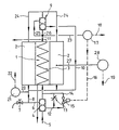
- the only drawing figure shows the circuit diagram of a water heater according to the invention.
- the heat exchanger 1 which is heated by a burner, not shown, is assigned a hot water tank 2, the design of which is basically arbitrary within the scope of the invention.
- this memory can encase or flank the heat exchanger.
- the heat exchanger 1 contains a coil 3 through which the heating water flows and which is surrounded by the water to be heated. This water is fed to the heat exchanger 1 via a hydraulic pressure switch 4 which is connected to a cold water supply line 5.
- This pressure switch 9 is connected to the output 11 of the heat exchanger 1.
- a throttle 13 In a branch line 12 starting from the pressure switch 4 there is a throttle 13 and in a further branch line 14 a cold water valve 15, which is controlled via a control line 16 by a controller 17, which in turn is connected via a control line 18 to a control of the flow temperature of the heating water stands.
- the storage thermostat 28 with the temperature sensor 27 is connected through the control line 19 to the higher-level control unit of the water heater.
- a pressure sensor 21 which is connected via a control line 22 to the control of the burner heating the heat exchanger 1.
- the second hydraulic switch 9 is connected via lines 11 and 25 to the heat exchanger, via line 10 to the tap line 8 and via line 24 to the accumulator 2.
- the control line 23 links the temperature transmitter 26 in line 11 to the temperature controller 17.
- the heating water circuit is switched to flow to heat exchanger 1.
- the thermal start-up phase is carried out on the primary and secondary sides of the system with throttled hot water throughput.
- the hot water flowing through the heat exchanger 1 flows via the pressure switch 9 and the lines 11, 25 and 25 to the reservoir 2.
- the controller 17 opens the cold water valve 15 via the control line 16 and releases the flow of the cold water to the coil 3 arranged in the heat exchanger 2 without throttling.
- the associated pressure increase in the heat exchanger 1 switches the switch 9 to the operating position in which it switches the hot water outlet via the flow line 24 to Memory 2 blocks and the bypass line 10 to the tap 8 and tap 7 opens.
- This tap 7 is now supplied by the heat exchanger 1 with hot water in the passage.
- the burner begins to operate in cyclical mode.
- the heating water temperature setpoint is reduced by the controller 18 connected downstream of the controller 17.
- the controller 18 connected downstream of the controller 17.
- the flow pressure in the pressure switches 4 and 9 drops to zero, and these pressure switches go into the rest position, releasing the circulation route via the flow 24 of the heat exchanger 1 and the return 6 for the thermal recharging of the store 2.
- the reloading process for which the burner may have to switch on several times, is completed as soon as the temperature sensor 27 of the storage thermostat 28 determines that the target value has been reached.
- a corresponding switching pulse is sent via the control line 19 to the higher-level control unit of the water heater.
Landscapes
- Engineering & Computer Science (AREA)
- Physics & Mathematics (AREA)
- Mechanical Engineering (AREA)
- Thermal Sciences (AREA)
- Chemical & Material Sciences (AREA)
- Combustion & Propulsion (AREA)
- General Engineering & Computer Science (AREA)
- Fluid Mechanics (AREA)
- Water Supply & Treatment (AREA)
- Instantaneous Water Boilers, Portable Hot-Water Supply Apparatuses, And Control Of Portable Hot-Water Supply Apparatuses (AREA)
- Heat-Pump Type And Storage Water Heaters (AREA)
- Domestic Hot-Water Supply Systems And Details Of Heating Systems (AREA)
- Resistance Heating (AREA)
- Cookers (AREA)
- Thermally Insulated Containers For Foods (AREA)
Applications Claiming Priority (2)
| Application Number | Priority Date | Filing Date | Title |
|---|---|---|---|
| AT1533/88 | 1988-06-14 | ||
| AT0153388A AT390504B (de) | 1988-06-14 | 1988-06-14 | Wasserheizer |
Publications (2)
| Publication Number | Publication Date |
|---|---|
| EP0346977A1 true EP0346977A1 (fr) | 1989-12-20 |
| EP0346977B1 EP0346977B1 (fr) | 1992-11-11 |
Family
ID=3515560
Family Applications (1)
| Application Number | Title | Priority Date | Filing Date |
|---|---|---|---|
| EP89201482A Expired - Lifetime EP0346977B1 (fr) | 1988-06-14 | 1989-06-09 | Chauffe-eau |
Country Status (5)
| Country | Link |
|---|---|
| EP (1) | EP0346977B1 (fr) |
| AT (2) | AT390504B (fr) |
| DE (2) | DE3918733A1 (fr) |
| ES (1) | ES2037394T3 (fr) |
| GR (1) | GR3006756T3 (fr) |
Cited By (1)
| Publication number | Priority date | Publication date | Assignee | Title |
|---|---|---|---|---|
| GB2306631A (en) * | 1995-10-28 | 1997-05-07 | Gledhill Water Storage | Domestic water heating apparatus |
Families Citing this family (3)
| Publication number | Priority date | Publication date | Assignee | Title |
|---|---|---|---|---|
| DE10344413B4 (de) * | 2003-09-25 | 2005-08-25 | Bbt Thermotechnik Gmbh | Verfahren zur Regelung der Warmwasserbereitung |
| CN109185950A (zh) * | 2018-10-24 | 2019-01-11 | 中冶华天南京电气工程技术有限公司 | 一种双分流换热站 |
| CN113074406B (zh) * | 2021-04-08 | 2022-05-10 | 湖南全家富电器科技有限公司 | 一种基于智能语音控制的家用取暖器 |
Citations (2)
| Publication number | Priority date | Publication date | Assignee | Title |
|---|---|---|---|---|
| FR1527970A (fr) * | 1967-04-14 | 1968-06-07 | Fonderie Soc Gen De | Installation assurant la production d'eau chaude sanitaire |
| DE3714968A1 (de) * | 1986-05-03 | 1987-11-05 | Vaillant Joh Gmbh & Co | Warmwasserversorgungsanlage |
-
1988
- 1988-06-14 AT AT0153388A patent/AT390504B/de not_active IP Right Cessation
-
1989
- 1989-06-08 DE DE3918733A patent/DE3918733A1/de not_active Withdrawn
- 1989-06-09 AT AT89201482T patent/ATE82378T1/de active
- 1989-06-09 DE DE8989201482T patent/DE58902658D1/de not_active Expired - Lifetime
- 1989-06-09 ES ES198989201482T patent/ES2037394T3/es not_active Expired - Lifetime
- 1989-06-09 EP EP89201482A patent/EP0346977B1/fr not_active Expired - Lifetime
-
1993
- 1993-01-08 GR GR920403161T patent/GR3006756T3/el unknown
Patent Citations (2)
| Publication number | Priority date | Publication date | Assignee | Title |
|---|---|---|---|---|
| FR1527970A (fr) * | 1967-04-14 | 1968-06-07 | Fonderie Soc Gen De | Installation assurant la production d'eau chaude sanitaire |
| DE3714968A1 (de) * | 1986-05-03 | 1987-11-05 | Vaillant Joh Gmbh & Co | Warmwasserversorgungsanlage |
Cited By (2)
| Publication number | Priority date | Publication date | Assignee | Title |
|---|---|---|---|---|
| GB2306631A (en) * | 1995-10-28 | 1997-05-07 | Gledhill Water Storage | Domestic water heating apparatus |
| GB2306631B (en) * | 1995-10-28 | 1999-01-20 | Gledhill Water Storage | Improvements relating to heating apparatus |
Also Published As
| Publication number | Publication date |
|---|---|
| ATE82378T1 (de) | 1992-11-15 |
| EP0346977B1 (fr) | 1992-11-11 |
| AT390504B (de) | 1990-05-25 |
| GR3006756T3 (fr) | 1993-06-30 |
| ATA153388A (de) | 1989-10-15 |
| DE58902658D1 (de) | 1992-12-17 |
| DE3918733A1 (de) | 1989-12-21 |
| ES2037394T3 (es) | 1993-06-16 |
Similar Documents
| Publication | Publication Date | Title |
|---|---|---|
| AT406191B (de) | Warmwasserheizung | |
| EP0098450B1 (fr) | Source de chaleur chauffée par combustible | |
| DE4034918A1 (de) | Verfahren zur ermoeglichung des sofortigen zapfens von warmem brauchwasser | |
| DE69518216T2 (de) | Wandgasheizkessel mit kleinem Brauchwasserspeicher | |
| AT390504B (de) | Wasserheizer | |
| EP0038318A1 (fr) | Dispositif de réglage pour le réglage du chauffage d'eau sanitaire pour un ballon de stockage | |
| DE19530000C2 (de) | Warmwasserbereitungsanlage | |
| DE4332141C2 (de) | Umlaufwasserheizer | |
| EP3800403B1 (fr) | Procédé de fonctionnement d'un dispositif de chauffage, dispositif de chauffage | |
| DE19617111A1 (de) | Wasserheizanlage | |
| EP0421312B1 (fr) | Dispositif pour commander le fonctionnement du chauffe-eau rapide pendant la distribution d'eau sanitaire. | |
| DE3310852C2 (de) | Umlaufwasserheizer | |
| EP0556736A1 (fr) | Procédé pour la commande d'une chaudière | |
| DE3917068A1 (de) | Aufheizsteuerung eines brauchwasserspeichers | |
| DE19802362C2 (de) | Verfahren und Einrichtung zur Reduzierung der Wartezeit für das Zapfen von warmem Brauchwasser | |
| EP0038964A2 (fr) | Chauffe-eau à accumulation | |
| EP0886110B1 (fr) | Méthode pour préparer l'eau sanitaire dans un système mixte | |
| DE4015139A1 (de) | Verfahren zur steuerung einer wasserheizungsanlage | |
| DE3322612A1 (de) | Brennstoffbeheizte waermequelle | |
| AT397854B (de) | Verfahren zur steuerung eines kessels | |
| EP0617240B1 (fr) | Chaudière mixte | |
| EP1158251B1 (fr) | Méthode pour régler une installation de chauffage d'eau | |
| EP0544622A1 (fr) | Installation à chaudières à deux combustibles d'un chauffage central avec une chaudière à bois et une chaudière à huile | |
| EP0452259B1 (fr) | Appareil pour produire l'eau chaude sanitaire et procédé pour la marche de l'appareil | |
| DE10033910A1 (de) | Schichtenspeicher |
Legal Events
| Date | Code | Title | Description |
|---|---|---|---|
| PUAI | Public reference made under article 153(3) epc to a published international application that has entered the european phase |
Free format text: ORIGINAL CODE: 0009012 |
|
| AK | Designated contracting states |
Kind code of ref document: A1 Designated state(s): AT BE CH DE ES FR GB GR IT LI LU NL SE |
|
| 17P | Request for examination filed |
Effective date: 19900618 |
|
| 17Q | First examination report despatched |
Effective date: 19910527 |
|
| RAP1 | Party data changed (applicant data changed or rights of an application transferred) |
Owner name: VAILLANT GMBH Owner name: VAILLANT-SCHONEWELLE B.V. Owner name: VAILLANT LTD. Owner name: VAILLANT GES.M.B.H Owner name: VAILLANT S.A.R.L Owner name: N.V. VAILLANT S.A. Owner name: JOH. VAILLANT GMBH U. CO. |
|
| GRAA | (expected) grant |
Free format text: ORIGINAL CODE: 0009210 |
|
| AK | Designated contracting states |
Kind code of ref document: B1 Designated state(s): AT BE CH DE ES FR GB GR IT LI LU NL SE |
|
| REF | Corresponds to: |
Ref document number: 82378 Country of ref document: AT Date of ref document: 19921115 Kind code of ref document: T |
|
| REF | Corresponds to: |
Ref document number: 58902658 Country of ref document: DE Date of ref document: 19921217 |
|
| GBT | Gb: translation of ep patent filed (gb section 77(6)(a)/1977) |
Effective date: 19921201 |
|
| ITF | It: translation for a ep patent filed | ||
| PGFP | Annual fee paid to national office [announced via postgrant information from national office to epo] |
Ref country code: LU Payment date: 19930315 Year of fee payment: 5 Ref country code: FR Payment date: 19930315 Year of fee payment: 5 |
|
| PGFP | Annual fee paid to national office [announced via postgrant information from national office to epo] |
Ref country code: SE Payment date: 19930316 Year of fee payment: 5 |
|
| ET | Fr: translation filed | ||
| PGFP | Annual fee paid to national office [announced via postgrant information from national office to epo] |
Ref country code: BE Payment date: 19930510 Year of fee payment: 5 |
|
| EPTA | Lu: last paid annual fee | ||
| REG | Reference to a national code |
Ref country code: GR Ref legal event code: FG4A Free format text: 3006756 |
|
| PGFP | Annual fee paid to national office [announced via postgrant information from national office to epo] |
Ref country code: GR Payment date: 19930609 Year of fee payment: 5 |
|
| PG25 | Lapsed in a contracting state [announced via postgrant information from national office to epo] |
Ref country code: ES Free format text: LAPSE BECAUSE OF NON-PAYMENT OF DUE FEES Effective date: 19930610 |
|
| REG | Reference to a national code |
Ref country code: ES Ref legal event code: FG2A Ref document number: 2037394 Country of ref document: ES Kind code of ref document: T3 |
|
| PLBE | No opposition filed within time limit |
Free format text: ORIGINAL CODE: 0009261 |
|
| STAA | Information on the status of an ep patent application or granted ep patent |
Free format text: STATUS: NO OPPOSITION FILED WITHIN TIME LIMIT |
|
| 26N | No opposition filed | ||
| PGFP | Annual fee paid to national office [announced via postgrant information from national office to epo] |
Ref country code: GB Payment date: 19940316 Year of fee payment: 6 |
|
| PG25 | Lapsed in a contracting state [announced via postgrant information from national office to epo] |
Ref country code: LU Free format text: LAPSE BECAUSE OF NON-PAYMENT OF DUE FEES Effective date: 19940609 |
|
| PG25 | Lapsed in a contracting state [announced via postgrant information from national office to epo] |
Ref country code: SE Effective date: 19940610 |
|
| PG25 | Lapsed in a contracting state [announced via postgrant information from national office to epo] |
Ref country code: BE Effective date: 19940630 |
|
| BERE | Be: lapsed |
Owner name: S.A. VAILLANT N.V. Effective date: 19940630 |
|
| PG25 | Lapsed in a contracting state [announced via postgrant information from national office to epo] |
Ref country code: GR Free format text: THE PATENT HAS BEEN ANNULLED BY A DECISION OF A NATIONAL AUTHORITY Effective date: 19941231 |
|
| EUG | Se: european patent has lapsed |
Ref document number: 89201482.0 Effective date: 19950110 |
|
| PG25 | Lapsed in a contracting state [announced via postgrant information from national office to epo] |
Ref country code: FR Effective date: 19950228 |
|
| EUG | Se: european patent has lapsed |
Ref document number: 89201482.0 |
|
| PGFP | Annual fee paid to national office [announced via postgrant information from national office to epo] |
Ref country code: DE Payment date: 19950328 Year of fee payment: 7 |
|
| REG | Reference to a national code |
Ref country code: FR Ref legal event code: ST Ref country code: GR Ref legal event code: MM2A Free format text: 3006756 |
|
| PG25 | Lapsed in a contracting state [announced via postgrant information from national office to epo] |
Ref country code: GB Effective date: 19950609 |
|
| PGFP | Annual fee paid to national office [announced via postgrant information from national office to epo] |
Ref country code: CH Payment date: 19950613 Year of fee payment: 7 |
|
| GBPC | Gb: european patent ceased through non-payment of renewal fee |
Effective date: 19950609 |
|
| PG25 | Lapsed in a contracting state [announced via postgrant information from national office to epo] |
Ref country code: LI Effective date: 19960630 Ref country code: CH Effective date: 19960630 |
|
| REG | Reference to a national code |
Ref country code: CH Ref legal event code: PL |
|
| PG25 | Lapsed in a contracting state [announced via postgrant information from national office to epo] |
Ref country code: DE Effective date: 19970301 |
|
| PGFP | Annual fee paid to national office [announced via postgrant information from national office to epo] |
Ref country code: NL Payment date: 19980312 Year of fee payment: 10 |
|
| PGFP | Annual fee paid to national office [announced via postgrant information from national office to epo] |
Ref country code: AT Payment date: 19980512 Year of fee payment: 10 |
|
| PG25 | Lapsed in a contracting state [announced via postgrant information from national office to epo] |
Ref country code: AT Free format text: LAPSE BECAUSE OF NON-PAYMENT OF DUE FEES Effective date: 19990609 |
|
| PG25 | Lapsed in a contracting state [announced via postgrant information from national office to epo] |
Ref country code: NL Free format text: LAPSE BECAUSE OF NON-PAYMENT OF DUE FEES Effective date: 20000101 |
|
| NLV4 | Nl: lapsed or anulled due to non-payment of the annual fee |
Effective date: 20000101 |
|
| REG | Reference to a national code |
Ref country code: ES Ref legal event code: FD2A Effective date: 20010503 |
|
| PG25 | Lapsed in a contracting state [announced via postgrant information from national office to epo] |
Ref country code: IT Free format text: LAPSE BECAUSE OF NON-PAYMENT OF DUE FEES;WARNING: LAPSES OF ITALIAN PATENTS WITH EFFECTIVE DATE BEFORE 2007 MAY HAVE OCCURRED AT ANY TIME BEFORE 2007. THE CORRECT EFFECTIVE DATE MAY BE DIFFERENT FROM THE ONE RECORDED. Effective date: 20050609 |