EP0347178A2 - Film de contrôle de l'orientation de molécules de cristal liquide et dispositif à cristal liquide l'utilisant - Google Patents
Film de contrôle de l'orientation de molécules de cristal liquide et dispositif à cristal liquide l'utilisant Download PDFInfo
- Publication number
- EP0347178A2 EP0347178A2 EP89305972A EP89305972A EP0347178A2 EP 0347178 A2 EP0347178 A2 EP 0347178A2 EP 89305972 A EP89305972 A EP 89305972A EP 89305972 A EP89305972 A EP 89305972A EP 0347178 A2 EP0347178 A2 EP 0347178A2
- Authority
- EP
- European Patent Office
- Prior art keywords
- liquid crystal
- coating
- orientation
- crystal element
- orientation control
- Prior art date
- Legal status (The legal status is an assumption and is not a legal conclusion. Google has not performed a legal analysis and makes no representation as to the accuracy of the status listed.)
- Withdrawn
Links
Images

Classifications
-
- G—PHYSICS
- G02—OPTICS
- G02F—OPTICAL DEVICES OR ARRANGEMENTS FOR THE CONTROL OF LIGHT BY MODIFICATION OF THE OPTICAL PROPERTIES OF THE MEDIA OF THE ELEMENTS INVOLVED THEREIN; NON-LINEAR OPTICS; FREQUENCY-CHANGING OF LIGHT; OPTICAL LOGIC ELEMENTS; OPTICAL ANALOGUE/DIGITAL CONVERTERS
- G02F1/00—Devices or arrangements for the control of the intensity, colour, phase, polarisation or direction of light arriving from an independent light source, e.g. switching, gating or modulating; Non-linear optics
- G02F1/01—Devices or arrangements for the control of the intensity, colour, phase, polarisation or direction of light arriving from an independent light source, e.g. switching, gating or modulating; Non-linear optics for the control of the intensity, phase, polarisation or colour
- G02F1/13—Devices or arrangements for the control of the intensity, colour, phase, polarisation or direction of light arriving from an independent light source, e.g. switching, gating or modulating; Non-linear optics for the control of the intensity, phase, polarisation or colour based on liquid crystals, e.g. single liquid crystal display cells
- G02F1/133—Constructional arrangements; Operation of liquid crystal cells; Circuit arrangements
-
- G—PHYSICS
- G02—OPTICS
- G02F—OPTICAL DEVICES OR ARRANGEMENTS FOR THE CONTROL OF LIGHT BY MODIFICATION OF THE OPTICAL PROPERTIES OF THE MEDIA OF THE ELEMENTS INVOLVED THEREIN; NON-LINEAR OPTICS; FREQUENCY-CHANGING OF LIGHT; OPTICAL LOGIC ELEMENTS; OPTICAL ANALOGUE/DIGITAL CONVERTERS
- G02F1/00—Devices or arrangements for the control of the intensity, colour, phase, polarisation or direction of light arriving from an independent light source, e.g. switching, gating or modulating; Non-linear optics
- G02F1/01—Devices or arrangements for the control of the intensity, colour, phase, polarisation or direction of light arriving from an independent light source, e.g. switching, gating or modulating; Non-linear optics for the control of the intensity, phase, polarisation or colour
- G02F1/13—Devices or arrangements for the control of the intensity, colour, phase, polarisation or direction of light arriving from an independent light source, e.g. switching, gating or modulating; Non-linear optics for the control of the intensity, phase, polarisation or colour based on liquid crystals, e.g. single liquid crystal display cells
- G02F1/133—Constructional arrangements; Operation of liquid crystal cells; Circuit arrangements
- G02F1/1333—Constructional arrangements; Manufacturing methods
- G02F1/1337—Surface-induced orientation of the liquid crystal molecules, e.g. by alignment layers
- G02F1/133711—Surface-induced orientation of the liquid crystal molecules, e.g. by alignment layers by organic films, e.g. polymeric films
- G02F1/133719—Surface-induced orientation of the liquid crystal molecules, e.g. by alignment layers by organic films, e.g. polymeric films with coupling agent molecules, e.g. silane
Definitions
- the present invention relates to an orientation control film of liquid crystal molecule and a liquid crystal element using said orientation control film.
- liquid crystal elements have come to be widely used in various fields such as for wrist watches, game machines, color television receivers, lap-top computers, and the like.
- the requirements for the high performance of the liquid crystal have been greatly enhanced.
- developments have been made on the high performance liquid crystal elements such as the liquid crystal elements using the active matrix system or super-twisted nematic liquid crystal system, or ferroelectric liquid crystal elements.
- orientation control technique it is a technique for orientating the liquid crystal molecules in a certain direction over the whole surface of the element, on which the display quality largely depends.
- the orientation control When the orientation control is unsatisfactory, fatal defects are induced such as unevenness of display, lowering in contrast, deterioration of performance with time, and the like.
- the importance of the orient-ation control technique applies commonly to each of the aforementioned high performance liquid crystal elements as well as to the conventional twisted nematic type liquid crystal elements. Rather, the orientation control technique has become a technique of higher importance.
- the method for controlling the orientation of the liquid crystal there have been employed a method of rubbing (rubbing method) and a method cf depositing SiO or the like on the electrode surface in oblique direction thereto (oblique deposition method), of which the rubbing method, which is simple and low in cost, is principally adopted.
- rubbing method a method of rubbing
- oblique deposition method a method cf depositing SiO or the like on the electrode surface in oblique direction thereto
- ferroelectric liquid crystal element there is proposed a liquid crystal element having a memory property by the surface stabilized ferroelectric liquid crystal element proposed by N. A. Clark, S. T. Lagerwall, et al. (U.S. Patent 4,367,924).
- N. A. Clark, S. T. Lagerwall, et al. U.S. Patent 4,367,924.
- it is necessary for both the even orientation and the assurance of the bistability of the liquid crystal molecule to be satisfied in the actual element.
- it has been impossible to satisfy both sufficient bistability and even orientation by the conventional process of using the film coated with polyimide or the like and simply rubbing it.
- the orientation of the ferroelectric liquid crystal involves specificity and difficulty of a degree beyond comparison with the conventional method.
- An object of the present invention is to realize an orientation condition of the liquid crystal molecules uniformly over the whole surface of the element and being free from defect. Another object is to obtain both the ascertainment of the bistability of the liquid crystal molecule and uniform orientation condition of the liquid crystal molecules in the ferroelectric liquid crystal element. A further object is to realise these factors in good mass-productivity and at low cost.
- a coating comprising protein as a main component is applied to at least one of a pair of substrates forming an electrode layer.
- a coating method to exert a shearing force to a certain direction e.g., a pull coating method, is employed, by which an orientation control film is completed even without the provision of an orientation treatment.
- the orientation control coating is completed by the provision of an orientation treatment such as rubbing.
- an orientation treatment such as rubbing may be provided so as to improve the orientation further.
- a pair of substrates having the orientation control coating thus formed are held in opposite relation to each other through a spacer bonded to the side of the orientation control coating as mentioned above, and liquid crystal material is injected into a space formed between the opposed coatings and held therein. By such construction, the liquid crystal molecules held in the space between the opposed coatings are aligned.
- a coating of the present invention comprising the protein as a main component, a thin and uniform orientation control coating can be realized. Further, when the above orientation control coating is employed, orientation condition of the liquid crystal molecules which is uniform over the whole surface of the element and is high in grade can be realized in good mass productivity and at low cost. Further, when it is applied to a ferroelectric liquid crystal element, satisfactory ferroelectric liquid crystal element with assurance of sufficient bistability can be realized in good mass productivity and at low cost for application to the liquid crystals having a large spontaneous polarization value (of at least 20 nC/cm2) as well as those having a small spontaneous polarization value.
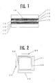
- Fig. 1 is a lateral sectional view showing a schematic construction of the liquid crystal element using the orientation control coating according to the present invention.
- a transparent electrode (ITO electrode) layer 12 comprising indium ⁇ tin oxide is formed, on which a coating is formed using a solution comprising protein as a main component.
- various coating methods in industrial practice such as spin coat process, roll coat process, printing process, air knife coat process, etc.
- orientation of liquid crystal molecules is obtained even without specially providing an orientation treatment.
- orientation treatment such as rubbing may be provided to make an orientation control coating 13.
- a spacer & seal resin 14 made by dispersing in resin a cylindrical or spherical spacer comprising glass or plastic is allowed to remain only partly as an opening for injection of liquid crystal, and screen printing is performed.
- Bovine serum albumin (2.5 g) was dissolved in pure water (497.5 g) to prepare an aqueous bovin serum albumin solution of 0.5 % by weight. Then, to this aqueous solution, a glass substrate provided with pattern of ITO electrode was descended at the rate of 100 mm/min. in a perpendicular direction to the water surface. On immersion to the desired portion, the glass substrate was allowed to stand still for 10 seconds, after which it was pulled up at the rate of 10 mm/min. in the direction perpendicular to the water surface. The substrate which completed coating was dried in an electric furnace at 110°C for 1 hour to complete an orientation control coating. The coating thickness was about 100 A.
- FIG. 2 is a plan view showing the TN type liquid crystal cell, wherein the numeral 21 shows an upper substrate, 22 a lower substrate, 23 and 24 the respective pulling up directions, 25 a spacer & sealing resin, and 26 an opening.
- the completed TN type liquid crystal cell showed good orientation condition.
- Bovine serum albumin (25.0 g) was diluted with pure water (475.0 g) to prepare a bovine serum diluted solution of 5.0 % by weight. Using this solution, a bovine serum orientation control coating was prepared by the method shown in Example A1. Using the resulting coating, a TN type liquid crystal cell was prepared by the method shown in Example A1. The completed TN type liquid crystal cell showed good orientation condition, and gave good electrooptic characteristic.
- Ovalbumin (2.5 g) was dissolved in pure water (497.5 g) to prepare an aqueous ovalbumin solution of 0.5 % by weight. Using this aqueous solution, an ovalbumin orientation control coating was prepared by the method shown in Example A1. Using the resulting coating, a TN type liquid crystal cell was prepared by the method shown in Example A1. The completed TN type liquid crystal cell showed good orientation condition, and gave good electrooptic characteristic.
- Chymotrypsin (2.5 g) was dissolved in pure water (497.5 g) to prepare an aqueous chymotrypsin solution of 0.5 % by weight.
- a chymotrypsin orientation control coating was prepared by the method shown in Example A1.
- a TN type liquid crystal cell was prepared by the method shown in Example A1. The completed TN type liquid crystal cell showed good orientation condition, and gave good electrooptic characteristic.
- Hemoglobin (2.5 g) was dissolved in pure water (497.5 g) to prepare an aqueous hemoglobin solution of 0.5 % by weight.
- a hemoglobin orientation control coating was prepared by the method shown in Example A1.
- a TN type liquid crystal cell was prepared by the method shown in Example A1. The completed TN type liquid crystal cell showed good orientation condition, and gave good electrooptic characteristic.
- Bovine serum albumin (5.0 g) was dissolved in pure water (495.0 g) to prepare an aqueous bovin serum albumin solution of 1.0 % by weight. Then, this aqueous solution was spin coated on a glass substrate provided with pattern of ITO electrode at 2,000 r.p.m. for 1 minute. The substrate which completed coating was dried in an electric furnace at 110°C for 1 hour. The coating thickness was about 200 A. After the drying, the coating was subjected to rubbing treatment in a single direction to complete an orientation control coating. Two glass substrates thus provided with a bovine serum albumin orientation control coating were made, and, as shown in Fig.
- TN type liquid crystal cell (made by Merck, article name: ZLI3225) was injected from the opening 26 under reduced pressure. After the injection, the opening 26 was sealed with a commercialized acid anhydride curing type epoxy resin to complete a so-called twisted nematic (TN) type liquid crystal cell.
- Fig. 2 is a plan view showing the TN type liquid crystal cell, wherein the numeral 21 shows an upper substrate, 22 a lower substrate, 23 and 24 the respective rubbing directions, 25 a spacer & sealing resin, and 26 an opening.
- the completed TN type liquid crystal cell showed good orientation condition free from unevenness of orientation.
- Bovine serum albumin (25.0 g) was diluted with pure water (475.0 g) to prepare a bovine serum diluted solution of 5.0 % by weight. Using this solution, a bovine serum orientation control coating was prepared by the method shown in Example B1. Using the resulting coating, a TN type liquid crystal cell was prepared by the method shown in Example B1. The completed TN type liquid crystal cell showed good orientation condition free from unevenness of orientation, and gave good electrooptic characteristic.
- Ovalbumin (5.0 g) was dissolved in pure water (495.0 g) to prepare an aqueous ovalbumin solution of 1.0 % by weight. Using this aqueous solution, an ovalbumin orientation control coating was prepared by the method shown in Example B1. Using the resulting coating, a TN type liquid crystal cell was prepared by the method shown in Example B1. The completed TN type liquid crystal cell showed good orientation condition free from unevenness of orientation, and gave good electrooptic characteristic.
- Chymotrypsin (5.0 g) was dissolved in pure water (495.0 g) to prepare an aqueous chymotrypsin solution of 1.0 % by weight. Using this aqueous solution, a chymotrypsin orientation control coating was prepared by the method shown in Example B1. Using the resulting coating, a TN type liquid crystal cell was prepared by the method shown in Example B1. The completed TN type liquid crystal cell showed good orientation condition free from unevenness of orientation, and gave good electrooptic characteristic.
- Hemoglobin (5.0 g) was dissolved in pure water (495.0 g) to prepare an aqueous hemoglobin solution of 1.0 % by weight.
- a hemoglobin orientation control coating was prepared by the method shown in Example B1.
- a TN type liquid crystal cell was prepared by the method shown in Example B1. The completed TN type liquid crystal cell showed good orientation condition free from unevenness of orientation, and gave good electrooptic characteristic.
- Bovine serum albumin (2.5 g) was dissolved in pure water (497.5 g) to prepare an aqueous bovin serum albumin solution of 0.5 % by weight. Then, to this aqueous solution, a glass substrate provided with pattern of ITO electrode was descended at the rate of 100 mm/min. in a perpendicular direction to the water surface. On immersion to the desired portion, the glass substrate was allowed to stand still for 10 seconds, after which it was pulled up at the rate of 10 mm/min. in the direction perpendicular to the water surface. The substrate which completed coating was dried in an electric furnace at 110°C for 1 hour to complete an orientation control coating. The coating thickness was about 100 A.
- Fig. 3 is a plan view showing the ferroelectric liquid crystal cell, wherein the numeral 31 shows an upper substrate, 32 a lower substrate, 33 and 34 the respective pulling up directions, 35 a spacer & sealing resin, and 36 an opening.
- the completed ferroelectric liquid crystal cell showed good orientation condition. By application of voltage, good electrooptic characteristic with assured bistability was obtained.
- Bovine serum albumin (25.0 g) was diluted with pure water (475.0 g) to prepare a bovine serum diluted solution of 5.0 % by weight. Using this solution, a bovine serum orientation control coating was prepared by the method shown in Example C1. Using the resulting coating, a ferroelectric liquid crystal cell was prepared by the method shown in Example C1. The completed ferroelectric liquid crystal cell showed good orientation condition, and, by application of voltage there was obtained good electrooptic characteristic with assurance of bistability.
- Ovalbumin (2.5 g) was dissolved in pure water (497.5 g) to prepare an aqueous ovalbumin solution of 0.5 % by weight. Using this solution, an ovalbumin orientation control coating was prepared by the method shown in Example C1. Using the resulting coating, a ferroelectric liquid crystal cell was prepared by the method shown in Example C1. The completed ferroelectric liquid crystal cell showed good orientation condition, and, by application of voltage there was obtained good electrooptic characteristic with assurance of bistability.
- Chymotrypsin (2.5 g) was dissolved in pure water (497.5 g) to prepare an aqueous chymotrypsin solution of 0.5 % by weight.
- a chymotrypsin orientation control coating was prepared by the method shown in Example C1.
- a ferroelectric liquid crystal cell was prepared by the method shown in Example C1. The completed ferroelectric liquid crystal cell showed good orientation condition, and, by application of voltage there was obtained good electrooptic characteristic with assurance of bistability.
- Hemoglobin (2.5 g) was dissolved in pure water (497.5 g) to prepare an aqueous hemoglobin solution of 0.5 % by weight.
- a hemoglobin orientation control coating was prepared by the method shown in Example C1.
- a ferroelectric liquid crystal cell was prepared by the method shown in Example C1. The completed ferroelectric liquid crystal cell showed good orientation condition, and, by application of voltage there was obtained good electrooptic characteristic with assurance of bistability.
- Bovine serum albumin (5.0 g) was dissolved in pure water (495.0 g) to prepare an aqueous bovin serum albumin solution of 1.0 % by weight. Then, this aqueous solution was spin coated on a glass substrate provided with pattern of ITO electrode at 2,000 r.p.m. for 1 minute. The substrate which completed coating was dried in an electric furnace at 110°C for 1 hour. The coating thickness was about 200 A. After the drying, the coating was subjected to rubbing treatment in a single direction to complete an orientation control coating. Two glass substrates thus provided with a bovine serum albumin orientation control coating were made, and, as shown in Fig.
- the opening 36 was sealed with a commercialized acid anhydride curing type epoxy resin.
- the product was heated to a temperature at which the sealed in liquid crystal showed isotropicity, i.e., to a vicinity of 80°C, after which the temperature was gradually reduced to complete a so-called ferroelectric liquid crystal cell.
- Fig. 3 is a plan view showing the ferroelectric liquid crystal cell, wherein the numeral 31 shows an upper substrate, 32 a lower substrate, 33 and 34 the respective rubbing directions, 35 a spacer & sealing resin, and 36 an opening.
- the completed ferroelectric liquid crystal cell showed good orientation condition. By application of voltage, good electrooptic characteristic with assured bistability was obtained.
- Bovine serum albumin (25.0 g) was diluted with pure water (475.0 g) to prepare a bovine serum diluted solution of 5.0 % by weight. Using this solution, a bovine serum orientation control coating was prepared by the method shown in Example D1. Using the resulting coating, a ferroelectric liquid crystal cell was prepared by the method shown in Example D1. The completed ferroelectric liquid crystal cell showed good orientation condition, and, by application of voltage there was obtained good electrooptic characteristic with assurance of bistability.
- Ovalbumin (5.0 g) was dissolved in pure water (495.0 g) to prepare an aqueous ovalbumin solution of 1.0 % by weight. Using this aqueous solution, an ovalbumin orientation control coating was prepared by the method shown in Example D1. Using the resulting coating, a ferroelectric liquid crystal cell was prepared by the method shown in Example D1. The completed ferroelectric liquid crystal cell showed good orientation condition without irregularity of orientation, and, by application of voltage there was obtained good electrooptic characteristic with assurance of bistability.
- Chymotrypsin (5.0 g) was dissolved in pure water (495.0 g) to prepare an aqueous chymotrypsin solution of 1.0 % by weight. Using this aqueous solution, a chymotrypsin orientation control coating was prepared by the method shown in Example D1. Using the resulting coating, a ferroelectric liquid crystal cell was prepared by the method shown in Example D1. The completed ferroelectric liquid crystal cell showed good orientation condition without irregularity of orientation, and, by application of voltage there was obtained good electrooptic characteristic with assurance of bistability.
- Hemoglobin (5.0 g) was dissolved in pure water (495.0 g) to prepare an aqueous hemoglobin solution of 1.0 % by weight.
- a hemoglobin orientation control coating was prepared by the method shown in Example D1.
- a ferroelectric liquid crystal cell was prepared by the method shown in Example D1. The completed ferroelectric liquid crystal cell showed good orientation condition without irregularity of orientation, and, by application of voltage there was obtained good electrooptic characteristic with assurance of bistability.
- any other coating process may be adopted insofar as it is a coating method in which a shearing force is applied in a certain direction.
- the direction corresponding to the pulling up direction is to be the direction in which the shearing force is applied.
- the present invention process is applicable to all coating methods including dip coating process, printing process, etc.
- the liquid crystals used for injection (article names: ZLI3225, ZLI3654 made by Merck) are not limited to them.
- description has been given on the TN type liquid crystal element and ferroelectric liquid crystal element only, but the present invention is effective for any other system of liquid crystal elements which necessitate the orientation control.
Landscapes
- Physics & Mathematics (AREA)
- Nonlinear Science (AREA)
- Spectroscopy & Molecular Physics (AREA)
- Mathematical Physics (AREA)
- Chemical & Material Sciences (AREA)
- Crystallography & Structural Chemistry (AREA)
- General Physics & Mathematics (AREA)
- Optics & Photonics (AREA)
- Liquid Crystal (AREA)
Applications Claiming Priority (8)
| Application Number | Priority Date | Filing Date | Title |
|---|---|---|---|
| JP147449/88 | 1988-06-15 | ||
| JP63147449A JPH022517A (ja) | 1988-06-15 | 1988-06-15 | 配向制御膜とそれを用いた液晶素子 |
| JP63313379A JPH02157823A (ja) | 1988-12-12 | 1988-12-12 | 配向制御膜および配向制御法および液晶表示素子 |
| JP313378/88 | 1988-12-12 | ||
| JP313379/88 | 1988-12-12 | ||
| JP63313378A JPH02157822A (ja) | 1988-12-12 | 1988-12-12 | 配向制御膜および配向制御法および液晶表示素子 |
| JP63313380A JPH02157824A (ja) | 1988-12-12 | 1988-12-12 | 液晶素子 |
| JP313380/88 | 1988-12-12 |
Publications (2)
| Publication Number | Publication Date |
|---|---|
| EP0347178A2 true EP0347178A2 (fr) | 1989-12-20 |
| EP0347178A3 EP0347178A3 (fr) | 1990-04-25 |
Family
ID=27472785
Family Applications (1)
| Application Number | Title | Priority Date | Filing Date |
|---|---|---|---|
| EP89305972A Withdrawn EP0347178A3 (fr) | 1988-06-15 | 1989-06-13 | Film de contrôle de l'orientation de molécules de cristal liquide et dispositif à cristal liquide l'utilisant |
Country Status (2)
| Country | Link |
|---|---|
| EP (1) | EP0347178A3 (fr) |
| KR (1) | KR910001434A (fr) |
Cited By (2)
| Publication number | Priority date | Publication date | Assignee | Title |
|---|---|---|---|---|
| EP0464623A1 (fr) * | 1990-06-27 | 1992-01-08 | Matsushita Electric Industrial Co., Ltd. | Dispositif d'affichage à cristaux liquides ferro-électriques |
| US7507991B2 (en) | 1991-06-19 | 2009-03-24 | Semiconductor Energy Laboratory Co., Ltd. | Electro-optical device and thin film transistor and method for forming the same |
Families Citing this family (1)
| Publication number | Priority date | Publication date | Assignee | Title |
|---|---|---|---|---|
| KR101120158B1 (ko) * | 2010-03-18 | 2012-03-22 | 가천대학교 산학협력단 | 액정을 이용하는 단백질 상호반응 디스플레이용 광학 셀 제조방법 |
Family Cites Families (6)
| Publication number | Priority date | Publication date | Assignee | Title |
|---|---|---|---|---|
| US3911167A (en) * | 1970-05-01 | 1975-10-07 | Texas Instruments Inc | Electron multiplier and method of making same |
| JPS5435780B2 (fr) * | 1974-07-23 | 1979-11-05 | ||
| FR2332550A1 (fr) * | 1975-11-19 | 1977-06-17 | Commissariat Energie Atomique | Procede et dispositifs d'orientation oblique des molecules d'un cristal liquide |
| DE3121945C2 (de) * | 1981-06-03 | 1984-02-02 | Wayss & Freytag Ag, 6000 Frankfurt | Doppelwandiger Behälter für tiefkalte Flüssigkeiten |
| JPS62286022A (ja) * | 1986-06-03 | 1987-12-11 | Seiko Instr & Electronics Ltd | 液晶表示素子およびその製造方法 |
| DE3727945A1 (de) * | 1986-08-22 | 1988-02-25 | Ricoh Kk | Fluessigkristallelement |
-
1989
- 1989-06-13 EP EP89305972A patent/EP0347178A3/fr not_active Withdrawn
- 1989-06-15 KR KR1019890008271A patent/KR910001434A/ko not_active Abandoned
Cited By (3)
| Publication number | Priority date | Publication date | Assignee | Title |
|---|---|---|---|---|
| EP0464623A1 (fr) * | 1990-06-27 | 1992-01-08 | Matsushita Electric Industrial Co., Ltd. | Dispositif d'affichage à cristaux liquides ferro-électriques |
| US7507991B2 (en) | 1991-06-19 | 2009-03-24 | Semiconductor Energy Laboratory Co., Ltd. | Electro-optical device and thin film transistor and method for forming the same |
| US7923311B2 (en) | 1991-06-19 | 2011-04-12 | Semiconductor Energy Laboratory Co., Ltd. | Electro-optical device and thin film transistor and method for forming the same |
Also Published As
| Publication number | Publication date |
|---|---|
| EP0347178A3 (fr) | 1990-04-25 |
| KR910001434A (ko) | 1991-01-30 |
Similar Documents
| Publication | Publication Date | Title |
|---|---|---|
| US4869577A (en) | Ferroelectric liquid crystal display device having uniaxial alignment on both substrates | |
| US4911958A (en) | Liquid crystal device | |
| JPH02157822A (ja) | 配向制御膜および配向制御法および液晶表示素子 | |
| US6642982B2 (en) | Liquid crystal display device with orientation film having projecting edge portions and manufacturing method of the same | |
| EP0347178A2 (fr) | Film de contrôle de l'orientation de molécules de cristal liquide et dispositif à cristal liquide l'utilisant | |
| US5657103A (en) | Liquid crystal device | |
| JPH0339932A (ja) | 液晶素子 | |
| KR0178418B1 (ko) | 액정패널의 제조방법 | |
| JP2532759B2 (ja) | 配向制御膜と液晶素子 | |
| JPH02208633A (ja) | 液晶表示装置 | |
| JPH02311822A (ja) | 配向制御膜と配向制御法および液晶素子 | |
| JP2568575B2 (ja) | 液晶セルの製造方法 | |
| JPH03288131A (ja) | 配向膜の形成方法及び液晶表示素子の製造方法 | |
| JPH0368924A (ja) | 液晶表示装置 | |
| JP2737330B2 (ja) | 液晶表示パネルの製造方法 | |
| JPH02157824A (ja) | 液晶素子 | |
| JP2548390B2 (ja) | 強誘電性液晶パネルの製造方法 | |
| CN1236332C (zh) | 偏光片及具有偏光片的薄膜晶体管阵列基板的制造方法 | |
| JPH02157823A (ja) | 配向制御膜および配向制御法および液晶表示素子 | |
| EP0464623B1 (fr) | Dispositif d'affichage à cristaux liquides ferro-électriques | |
| JPH0372323A (ja) | 液晶表示素子の製造法 | |
| JPH0756176A (ja) | 強誘電性液晶素子 | |
| JP2853198B2 (ja) | 液晶表示装置およびその製造方法 | |
| JPH0331821A (ja) | 液晶電気光学装置 | |
| JPH0786612B2 (ja) | 液晶パネルの製造方法 |
Legal Events
| Date | Code | Title | Description |
|---|---|---|---|
| PUAI | Public reference made under article 153(3) epc to a published international application that has entered the european phase |
Free format text: ORIGINAL CODE: 0009012 |
|
| AK | Designated contracting states |
Kind code of ref document: A2 Designated state(s): DE FR GB NL |
|
| PUAL | Search report despatched |
Free format text: ORIGINAL CODE: 0009013 |
|
| AK | Designated contracting states |
Kind code of ref document: A3 Designated state(s): DE FR GB NL |
|
| 17P | Request for examination filed |
Effective date: 19901015 |
|
| 17Q | First examination report despatched |
Effective date: 19920915 |
|
| STAA | Information on the status of an ep patent application or granted ep patent |
Free format text: STATUS: THE APPLICATION IS DEEMED TO BE WITHDRAWN |
|
| 18D | Application deemed to be withdrawn |
Effective date: 19931119 |