EP0347191A1 - Farbbildschirm-Kontrollsystem - Google Patents
Farbbildschirm-Kontrollsystem Download PDFInfo
- Publication number
- EP0347191A1 EP0347191A1 EP89305997A EP89305997A EP0347191A1 EP 0347191 A1 EP0347191 A1 EP 0347191A1 EP 89305997 A EP89305997 A EP 89305997A EP 89305997 A EP89305997 A EP 89305997A EP 0347191 A1 EP0347191 A1 EP 0347191A1
- Authority
- EP
- European Patent Office
- Prior art keywords
- display
- screen
- colour
- control
- reference pixel
- Prior art date
- Legal status (The legal status is an assumption and is not a legal conclusion. Google has not performed a legal analysis and makes no representation as to the accuracy of the status listed.)
- Granted
Links
- 230000003287 optical effect Effects 0.000 claims abstract description 21
- 239000003086 colorant Substances 0.000 claims abstract description 14
- 230000005855 radiation Effects 0.000 claims abstract description 14
- 238000000034 method Methods 0.000 claims description 4
- 230000001419 dependent effect Effects 0.000 claims 1
- 230000032683 aging Effects 0.000 description 3
- 230000000694 effects Effects 0.000 description 3
- 238000010586 diagram Methods 0.000 description 2
- 238000001228 spectrum Methods 0.000 description 2
- OAICVXFJPJFONN-UHFFFAOYSA-N Phosphorus Chemical group [P] OAICVXFJPJFONN-UHFFFAOYSA-N 0.000 description 1
- 238000010894 electron beam technology Methods 0.000 description 1
- 238000012544 monitoring process Methods 0.000 description 1
- 238000011112 process operation Methods 0.000 description 1
- 230000000007 visual effect Effects 0.000 description 1
Images

Classifications
-
- H—ELECTRICITY
- H04—ELECTRIC COMMUNICATION TECHNIQUE
- H04N—PICTORIAL COMMUNICATION, e.g. TELEVISION
- H04N5/00—Details of television systems
- H04N5/44—Receiver circuitry for the reception of television signals according to analogue transmission standards
- H04N5/57—Control of contrast or brightness
- H04N5/58—Control of contrast or brightness in dependence upon ambient light
Definitions
- the invention relates to a colour display control system and in particular, a system for controlling the optical characteristics of a visual display.
- the colour appearance of a display can also change. These changes can be due to flare from the screen which is related to the viewing angle and the ambient light level. Hence, the colour of the display perceived by the operator will change during the day and may also vary from one display to another. The effects of aging on the display will also change the colour perceived by an operator.
- a colour display control system for use with a display having a screen capable of being activated so as to generate at least two colours, the system comprising at least one optical sensor which detects optical radiation emitted from the display screen corresponding to each of the colours generated by the screen, and control means responsive to an output signal form the sensor related to the intensity of the detected radiation to control the optical characteristics of the display so that the detected colour is generated in a predetermined manner.
- This invention enables a colour display to be compensated for changes in its optical characteristics and for any changes in the ambient lighting conditions.
- the display to be controlled would be a high resolution colour cathode ray tube (CRT) display, although the invention could be used with any other suitable type of display.
- CRT cathode ray tube
- a number of phosphors are provided on the screen in an array of regions, the phosphors being activatable to generate one of three colours: red, green and blue.
- the invention enables the individual ageing of one of the phosphors to be determined and corrected without affecting the others.
- the reference to activated colours refers to the actual colours generated by the screen (e.g. red, green or blue) and not to the resultant colour perceived by a viewer when a number of individual colours are activated together.
- the system comprises two optical sensors, mounted in diagonally opposite corners of the display.
- the or each sensor is mounted at a distance of about 2.5cm to 4cm away from the surface of the display.
- the sensors comprise photo-multiplier tubes but alternatively they could comprise photo-diodes.
- control means causes the display screen to display alternately at least two reference pixels constituting different ones of the said colours to be detected by the sensors.
- these comprise a red reference pixel, a green reference pixel and a blue reference pixel corresponding to the three phosphors of a CRT.
- a pixel in this context will comprise the smallest region which can be defined by modulating a display control signal (typically an electron beam) but will consist of a number of different colour phosphor regions.
- control means will control the image signals applied to the display but it would also be feasible to control the ambient light in certain circumstances.
- optical we mean not only radiation in the optical region of the spectrum but also radiation in the infra-red and ultra-violet regions of the spectrum.
- Figure 1 shows a display device 1 having a screen 2 which is part of a cathode ray tube 3.
- Two sensors 4, 5 are positioned at the top left hand corner of the screen and at the bottom right hand corner of the screen respectively so that they sense optical radiation emitted by pixel areas 6, 7.
- the sensors 4, 5 are positioned at between 2.5cm and 4cm from the surface of the screen 2.
- the output intensity signals 8, 9 from the respective sensors 4, 5 are fed to a processing unit 10 which maintains overall control of the display control system.
- a video driver 11 has three input lines 17 on which are received input image colour signals R, G, B.
- the video driver 11 is connected to the cathode ray tube 3 by four lines 12 which supply colour signals R′, G′, B′ to control the colour of the image produced by the cathode ray tube 3 and a synchronising signal S′ necessary for raster control.
- a reference pixel control unit 13 controls the type of reference pixel which is displayed in the pixel areas 6, 7.
- the type of reference pixel displayed in the pixel areas 6, 7 may be either a red pixel, a green pixel, or a blue pixel corresponding to the colours of the phosphors on the screen 2.
- the reference pixel control unit 13 is connected to the processing unit 10 by a line 14.
- the line 14 is used by the processing unit 10 to transmit to the reference pixel control unit 13 the type of reference pixel to be displayed in the pixel areas 6, 7.
- the processing unit 10 is also connected to the video driver 11 directly by means of lines 15, which supply colour correction signals R c , G c , B c to the video driver 11 which enables the colour control signals R, G, B which are input to the video driver 11 to be modified to output signals R′, G′, B′ which are applied to the cathode ray tube to correct the colour of the display.
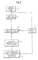
- the display unit 1 normally displays an image in a conventional manner as defined by the signals on lines 17.
- the processing unit 10 sends a signal via line 14 to the reference pixel control unit 13.
- the reference pixel control unit 13 then sends a signal, representative of the type of reference pixel to be displayed, via line 16 to the video driver unit 11.
- the video driver unit 11 displays the corresponding reference pixel in the pixel areas 6, 7 on the screen 2 of the cathode ray tube 3 while the remainder of the screen 2 displays the image.
- the reference pixels are displayed for 1 60 second and will not be seen by the viewer.
- the sensors 4, 5 which would typically be photo-multiplier tubes, detect the amplitude of the radiation emitted from the pixel areas 6, 7 and a signal related to the amplitude is transmitted to the processing unit 10 via the lines 8, 9.
- the processing unit 10 compares the actual signals from the sensors 4, 5 with a reference value for the particular type of reference pixel which is displayed. (The reference values are set up by generating each reference pixel while the CRT is in darkness and storing the resultant signals from the sensors.) If the signals from the sensors 4, 5 are equal (within acceptable tolerances) to the reference value then that particular colour is set correctly and the processing unit 10 signals the reference pixel control unit 13 via the line 14 to display the next reference pixel.
- the processing unit 10 calculates a colour correction value R c , G c or B c .
- the particular correction value R c , G c or B c is then transmitted on the appropriate line 15 to the video driver 11 and the correction signal R c , G c or B c , is then used to modify the input colour signal R, G or B to the video driver 11 to get a modified output signal R′, G′ or B′, which is applied on the lines 12 to the cathode ray tube 3.
- the reference pixel control 13 is signalled to display 23 the next reference pixel (e.g. blue), and the process commences again from step 21.
Landscapes
- Engineering & Computer Science (AREA)
- Multimedia (AREA)
- Signal Processing (AREA)
- Controls And Circuits For Display Device (AREA)
- Processing Of Color Television Signals (AREA)
- Testing, Inspecting, Measuring Of Stereoscopic Televisions And Televisions (AREA)
Applications Claiming Priority (2)
| Application Number | Priority Date | Filing Date | Title |
|---|---|---|---|
| GB888814157A GB8814157D0 (en) | 1988-06-15 | 1988-06-15 | Display control system |
| GB8814157 | 1988-06-15 |
Publications (2)
| Publication Number | Publication Date |
|---|---|
| EP0347191A1 true EP0347191A1 (de) | 1989-12-20 |
| EP0347191B1 EP0347191B1 (de) | 1993-09-29 |
Family
ID=10638699
Family Applications (1)
| Application Number | Title | Priority Date | Filing Date |
|---|---|---|---|
| EP89305997A Expired - Lifetime EP0347191B1 (de) | 1988-06-15 | 1989-06-14 | Farbbildschirm-Kontrollsystem |
Country Status (5)
| Country | Link |
|---|---|
| US (1) | US5083195A (de) |
| EP (1) | EP0347191B1 (de) |
| JP (1) | JP2847108B2 (de) |
| DE (1) | DE68909505T2 (de) |
| GB (1) | GB8814157D0 (de) |
Cited By (7)
| Publication number | Priority date | Publication date | Assignee | Title |
|---|---|---|---|---|
| FR2710174A1 (fr) * | 1993-09-16 | 1995-03-24 | Le Falher Jean Richard | Dispositif de surveillance des couleurs d'un système d'affichage. |
| EP0753236A4 (de) * | 1994-03-29 | 1998-07-15 | Radius Inc | Methode und vorrichtung zur dynamischen reinheitskorrektur |
| GB2343744A (en) * | 1998-11-11 | 2000-05-17 | Cashmaster Int Ltd | Monitoring apparatus |
| EP0987528A3 (de) * | 1998-09-18 | 2000-12-06 | Fujitsu Limited | Datenverarbeitungsanordnung mit einer Farbanzeigeeinheit |
| WO2002047395A3 (en) * | 2000-12-05 | 2003-01-16 | Univ Columbia | Method and apparatus for displaying images |
| EP2200334A1 (de) * | 2008-12-18 | 2010-06-23 | Thomson Licensing | Anzeigevorrichtung mit Feedbackelementen und Überwachungsverfahren |
| ITRM20120630A1 (it) * | 2012-12-11 | 2014-06-12 | Taggalo S R L | Metodo e sistema per il monitoraggio della visualizzazione di contenuti video |
Families Citing this family (21)
| Publication number | Priority date | Publication date | Assignee | Title |
|---|---|---|---|---|
| US5172221A (en) * | 1989-12-29 | 1992-12-15 | Samsung Electronics Co., Ltd. | Picture projecting apparatus for a projection display system and the method thereof |
| US5363318A (en) * | 1992-03-23 | 1994-11-08 | Eastman Kodak Company | Method and apparatus for adaptive color characterization and calibration |
| EP0604755B1 (de) * | 1992-12-15 | 1999-05-12 | E.I. Du Pont De Nemours And Company | Farbangleichungsverfahren und -Gerät |
| FI925957A7 (fi) * | 1992-12-30 | 1994-07-01 | Icl Personal Systems Oy | Ohjausjärjestelmä yhtä tai useampaa työpistettä varten |
| US7728845B2 (en) | 1996-02-26 | 2010-06-01 | Rah Color Technologies Llc | Color calibration of color image rendering devices |
| US6043909A (en) * | 1996-02-26 | 2000-03-28 | Imagicolor Corporation | System for distributing and controlling color reproduction at multiple sites |
| US6459425B1 (en) * | 1997-08-25 | 2002-10-01 | Richard A. Holub | System for automatic color calibration |
| JPH1075468A (ja) * | 1996-08-30 | 1998-03-17 | Sony Corp | フォーカス測定方法 |
| KR19980052323A (ko) * | 1996-12-24 | 1998-09-25 | 구자홍 | 온도센서를 이용한 자동 색온도 조정장치 |
| DE19934721A1 (de) * | 1999-06-24 | 2001-01-04 | Peter Adrian | Einrichtung zur Erfassung und Auswertung von arbeitsplatzrelevanten Daten an Arbeitsplätzen |
| US7102648B1 (en) | 2000-04-11 | 2006-09-05 | Rah Color Technologies Llc | Methods and apparatus for calibrating a color display |
| US20020180750A1 (en) * | 2001-05-29 | 2002-12-05 | Imation Corp. | Display system |
| US7218418B2 (en) * | 2002-07-01 | 2007-05-15 | Xerox Corporation | Digital de-screening of documents |
| SE525845C2 (sv) * | 2003-01-20 | 2005-05-10 | Ao Medical Products Sweden Ab | Anordning och förfarande för reglering av en platsbelysning |
| CN100539630C (zh) * | 2003-04-02 | 2009-09-09 | 伊斯曼柯达公司 | 确保软打样系统的精确测量 |
| WO2005015490A2 (en) * | 2003-07-02 | 2005-02-17 | Trustees Of Columbia University In The City Of New York | Methods and systems for compensating an image projected onto a surface having spatially varying photometric properties |
| US7483576B2 (en) * | 2004-02-02 | 2009-01-27 | Adams Platform Pty Ltd. | System and method for decoding video |
| WO2006047487A2 (en) * | 2004-10-25 | 2006-05-04 | The Trustees Of Columbia University In The City Of New York | Systems and methods for displaying three-dimensional images |
| US8248454B2 (en) * | 2007-11-14 | 2012-08-21 | Hewlett-Packard Development Company, L.P. | Video display calibration system and method |
| US20090184947A1 (en) * | 2008-01-22 | 2009-07-23 | Hupman Paul M | Color calibration system and method |
| US11705028B2 (en) | 2020-06-19 | 2023-07-18 | GeoPost, Inc. | Mobile device fixture for automated calibration of electronic display screens and method of use |
Citations (4)
| Publication number | Priority date | Publication date | Assignee | Title |
|---|---|---|---|---|
| DE1462027A1 (de) * | 1965-12-30 | 1969-01-02 | Siemens Ag | Vorrichtung zum selbsttaetigen Einstellen der Grundhelligkeit und/oder des Kontrastes des Bildes in einem Fernsehempfaenger |
| US3471740A (en) * | 1965-05-04 | 1969-10-07 | Photo Electronics Corp | Method and apparatus for controlling cathode ray tube brightness and contrast |
| US3715617A (en) * | 1970-07-10 | 1973-02-06 | Sperry Rand Corp | Optical probe for cathode ray tubes |
| GB1585063A (en) * | 1977-06-13 | 1981-02-25 | Ferranti Ltd | Display systems |
Family Cites Families (12)
| Publication number | Priority date | Publication date | Assignee | Title |
|---|---|---|---|---|
| GB158563A (en) * | 1920-01-26 | 1922-05-26 | Frank Fred Bessinger | Improvements in piston rings |
| JPS5712620Y2 (de) * | 1974-05-20 | 1982-03-12 | ||
| US3962722A (en) * | 1974-11-27 | 1976-06-08 | Zenith Radio Corporation | Color television setup apparatus and method |
| US4001877A (en) * | 1975-11-26 | 1977-01-04 | Rca Corporation | Method of measuring color purity tolerance of a color display tube |
| JPS534427A (en) * | 1975-12-31 | 1978-01-17 | Matsushita Electric Ind Co Ltd | Color tv receiver |
| JPS6123915A (ja) * | 1984-07-12 | 1986-02-01 | Matsushita Electric Ind Co Ltd | 回転センサ |
| JPS61161093A (ja) * | 1985-01-09 | 1986-07-21 | Sony Corp | ダイナミツクユニフオミテイ補正装置 |
| JPS61167991A (ja) * | 1985-01-21 | 1986-07-29 | 株式会社日立製作所 | 自動色調節付カラ−デイスプレイ装置 |
| JPS61172495A (ja) * | 1985-01-27 | 1986-08-04 | Sony Corp | 映像信号表示装置 |
| US4700218A (en) * | 1985-04-12 | 1987-10-13 | Conrac Corporation | Automated system for adjustment of the white balance in a signal displayed on the screen of a color cathode ray tube |
| US4706108A (en) * | 1985-04-12 | 1987-11-10 | Sony Corporation | Automatic setup system for controlling color gain, hue and white balance of TV monitor |
| US4742387A (en) * | 1986-03-17 | 1988-05-03 | Sony Corporation | Method and apparatus for automatically establishing a color balance of a color television monitor including an ambient light sensing and data compensating function |
-
1988
- 1988-06-15 GB GB888814157A patent/GB8814157D0/en active Pending
-
1989
- 1989-06-14 DE DE89305997T patent/DE68909505T2/de not_active Expired - Fee Related
- 1989-06-14 EP EP89305997A patent/EP0347191B1/de not_active Expired - Lifetime
- 1989-06-15 US US07/366,705 patent/US5083195A/en not_active Expired - Fee Related
- 1989-06-15 JP JP1150659A patent/JP2847108B2/ja not_active Expired - Lifetime
Patent Citations (4)
| Publication number | Priority date | Publication date | Assignee | Title |
|---|---|---|---|---|
| US3471740A (en) * | 1965-05-04 | 1969-10-07 | Photo Electronics Corp | Method and apparatus for controlling cathode ray tube brightness and contrast |
| DE1462027A1 (de) * | 1965-12-30 | 1969-01-02 | Siemens Ag | Vorrichtung zum selbsttaetigen Einstellen der Grundhelligkeit und/oder des Kontrastes des Bildes in einem Fernsehempfaenger |
| US3715617A (en) * | 1970-07-10 | 1973-02-06 | Sperry Rand Corp | Optical probe for cathode ray tubes |
| GB1585063A (en) * | 1977-06-13 | 1981-02-25 | Ferranti Ltd | Display systems |
Non-Patent Citations (2)
| Title |
|---|
| PATENT ABSTRACTS OF JAPAN, vol. 2, no. 40 (E-022), 16th March 1978, page 184 E 78; & JP-A-53 004 427 (MATSUSHITA DENKI SANGYO K.K.) 17-01-1978 * |
| SOCIETY FOR INFORMATION DISPLAY, INTERNATIONAL SYMPOSIUM, DIGEST OF TECHNICAL PAPERS, New Orleans, Louisiana, 12th-14th May 1987, vol. XVIII, pages 412-415, Palisades Institute for Research Services, Inc., New York, US; H. HOSOKAWA et al.: "Digital CRT luminance uniformity correction" * |
Cited By (8)
| Publication number | Priority date | Publication date | Assignee | Title |
|---|---|---|---|---|
| FR2710174A1 (fr) * | 1993-09-16 | 1995-03-24 | Le Falher Jean Richard | Dispositif de surveillance des couleurs d'un système d'affichage. |
| EP0753236A4 (de) * | 1994-03-29 | 1998-07-15 | Radius Inc | Methode und vorrichtung zur dynamischen reinheitskorrektur |
| EP0987528A3 (de) * | 1998-09-18 | 2000-12-06 | Fujitsu Limited | Datenverarbeitungsanordnung mit einer Farbanzeigeeinheit |
| US6734869B2 (en) | 1998-09-18 | 2004-05-11 | Fujitsu Limited | Information processing apparatus, profile data creating method, display unit and storage medium |
| GB2343744A (en) * | 1998-11-11 | 2000-05-17 | Cashmaster Int Ltd | Monitoring apparatus |
| WO2002047395A3 (en) * | 2000-12-05 | 2003-01-16 | Univ Columbia | Method and apparatus for displaying images |
| EP2200334A1 (de) * | 2008-12-18 | 2010-06-23 | Thomson Licensing | Anzeigevorrichtung mit Feedbackelementen und Überwachungsverfahren |
| ITRM20120630A1 (it) * | 2012-12-11 | 2014-06-12 | Taggalo S R L | Metodo e sistema per il monitoraggio della visualizzazione di contenuti video |
Also Published As
| Publication number | Publication date |
|---|---|
| DE68909505D1 (de) | 1993-11-04 |
| JP2847108B2 (ja) | 1999-01-13 |
| US5083195A (en) | 1992-01-21 |
| EP0347191B1 (de) | 1993-09-29 |
| GB8814157D0 (en) | 1988-07-20 |
| JPH02118595A (ja) | 1990-05-02 |
| DE68909505T2 (de) | 1994-01-20 |
Similar Documents
| Publication | Publication Date | Title |
|---|---|---|
| EP0347191B1 (de) | Farbbildschirm-Kontrollsystem | |
| US8159503B2 (en) | Method for adjusting brightness, contrast and color in a displaying apparatus | |
| US6791566B1 (en) | Image display device | |
| US7545397B2 (en) | Enhancing contrast | |
| AU607723B2 (en) | Liquid crystal display apparatus | |
| US8026908B2 (en) | Illuminated surround and method for operating same for video and other displays | |
| JP3701609B2 (ja) | 投射型映像表示機器の画質補償装置及び方法 | |
| US7614753B2 (en) | Determining an adjustment | |
| US20070291053A1 (en) | Image display device and image display method | |
| EP0801507B1 (de) | LCD-Projektor | |
| US5237246A (en) | Process and device for adjusting pictures | |
| US6327708B1 (en) | System of absolute measurement for radiological image luminance control | |
| JP2900966B2 (ja) | 画像表示方法およびその装置 | |
| US5018007A (en) | Thin projection screen having a liquid crystal display screen overlaid a sheet of fiber optic cables | |
| KR100802224B1 (ko) | 표시장치 및 그 제어방법 | |
| JPH07333760A (ja) | 自動調整システム | |
| CN114582260A (zh) | 颜色矫正方法及光纤扫描成像系统 | |
| EP1315384A1 (de) | Verfahren und System zur Kompensation einer durch Primärfarbunterschiede verursachten uneinheitlichen Farbdarstellung in Bildschirmen | |
| KR200172695Y1 (ko) | 텔레비젼 수상기의 화이트 밸런스 자동조정장치 | |
| JPH06217242A (ja) | 画像表示装置 | |
| KR20000009068U (ko) | 프로젝션 텔레비전에서 화면색 자동조정장치 | |
| JPH0937281A (ja) | オートホワイトバランス回路 | |
| JPH07143506A (ja) | 投射型ディスプレイ装置 | |
| JPH07203478A (ja) | 白色点自動補正装置 | |
| JPH09198019A (ja) | 画像表示方法および装置 |
Legal Events
| Date | Code | Title | Description |
|---|---|---|---|
| PUAI | Public reference made under article 153(3) epc to a published international application that has entered the european phase |
Free format text: ORIGINAL CODE: 0009012 |
|
| AK | Designated contracting states |
Kind code of ref document: A1 Designated state(s): DE GB |
|
| 17P | Request for examination filed |
Effective date: 19900315 |
|
| RAP1 | Party data changed (applicant data changed or rights of an application transferred) |
Owner name: CROSFIELD ELECTRONICS LIMITED |
|
| RAP1 | Party data changed (applicant data changed or rights of an application transferred) |
Owner name: CROSFIELD ELECTRONICS LIMITED |
|
| 17Q | First examination report despatched |
Effective date: 19920715 |
|
| GRAA | (expected) grant |
Free format text: ORIGINAL CODE: 0009210 |
|
| AK | Designated contracting states |
Kind code of ref document: B1 Designated state(s): DE GB |
|
| REF | Corresponds to: |
Ref document number: 68909505 Country of ref document: DE Date of ref document: 19931104 |
|
| PLBE | No opposition filed within time limit |
Free format text: ORIGINAL CODE: 0009261 |
|
| STAA | Information on the status of an ep patent application or granted ep patent |
Free format text: STATUS: NO OPPOSITION FILED WITHIN TIME LIMIT |
|
| 26N | No opposition filed | ||
| REG | Reference to a national code |
Ref country code: GB Ref legal event code: 732E |
|
| REG | Reference to a national code |
Ref country code: GB Ref legal event code: 746 Effective date: 20010312 |
|
| PGFP | Annual fee paid to national office [announced via postgrant information from national office to epo] |
Ref country code: GB Payment date: 20010712 Year of fee payment: 13 |
|
| PGFP | Annual fee paid to national office [announced via postgrant information from national office to epo] |
Ref country code: DE Payment date: 20010723 Year of fee payment: 13 |
|
| REG | Reference to a national code |
Ref country code: GB Ref legal event code: IF02 |
|
| PG25 | Lapsed in a contracting state [announced via postgrant information from national office to epo] |
Ref country code: GB Free format text: LAPSE BECAUSE OF NON-PAYMENT OF DUE FEES Effective date: 20020614 |
|
| PG25 | Lapsed in a contracting state [announced via postgrant information from national office to epo] |
Ref country code: DE Free format text: LAPSE BECAUSE OF NON-PAYMENT OF DUE FEES Effective date: 20030101 |
|
| GBPC | Gb: european patent ceased through non-payment of renewal fee |
Effective date: 20020614 |