EP0347363A1 - Dispositif pour diminuer la résistance à l'avancement d'un bateau - Google Patents
Dispositif pour diminuer la résistance à l'avancement d'un bateau Download PDFInfo
- Publication number
- EP0347363A1 EP0347363A1 EP89600011A EP89600011A EP0347363A1 EP 0347363 A1 EP0347363 A1 EP 0347363A1 EP 89600011 A EP89600011 A EP 89600011A EP 89600011 A EP89600011 A EP 89600011A EP 0347363 A1 EP0347363 A1 EP 0347363A1
- Authority
- EP
- European Patent Office
- Prior art keywords
- vessel
- conductor
- bow
- conductors
- decrease
- Prior art date
- Legal status (The legal status is an assumption and is not a legal conclusion. Google has not performed a legal analysis and makes no representation as to the accuracy of the status listed.)
- Withdrawn
Links
- XLYOFNOQVPJJNP-UHFFFAOYSA-N water Substances O XLYOFNOQVPJJNP-UHFFFAOYSA-N 0.000 claims abstract description 17
- 239000004020 conductor Substances 0.000 claims description 42
- 238000009434 installation Methods 0.000 claims description 3
- 238000000034 method Methods 0.000 description 9
- 239000000295 fuel oil Substances 0.000 description 4
- XEEYBQQBJWHFJM-UHFFFAOYSA-N Iron Chemical compound [Fe] XEEYBQQBJWHFJM-UHFFFAOYSA-N 0.000 description 2
- 208000036366 Sensation of pressure Diseases 0.000 description 1
- 229910000831 Steel Inorganic materials 0.000 description 1
- 238000010276 construction Methods 0.000 description 1
- 239000000446 fuel Substances 0.000 description 1
- 229910052742 iron Inorganic materials 0.000 description 1
- 230000002787 reinforcement Effects 0.000 description 1
- 239000013535 sea water Substances 0.000 description 1
- 238000007493 shaping process Methods 0.000 description 1
- 239000010959 steel Substances 0.000 description 1
Images
Classifications
-
- B—PERFORMING OPERATIONS; TRANSPORTING
- B63—SHIPS OR OTHER WATERBORNE VESSELS; RELATED EQUIPMENT
- B63B—SHIPS OR OTHER WATERBORNE VESSELS; EQUIPMENT FOR SHIPPING
- B63B1/00—Hydrodynamic or hydrostatic features of hulls or of hydrofoils
- B63B1/32—Other means for varying the inherent hydrodynamic characteristics of hulls
- B63B1/40—Other means for varying the inherent hydrodynamic characteristics of hulls by diminishing wave resistance
-
- B—PERFORMING OPERATIONS; TRANSPORTING
- B63—SHIPS OR OTHER WATERBORNE VESSELS; RELATED EQUIPMENT
- B63H—MARINE PROPULSION OR STEERING
- B63H5/00—Arrangements on vessels of propulsion elements directly acting on water
- B63H5/07—Arrangements on vessels of propulsion elements directly acting on water of propellers
- B63H5/16—Arrangements on vessels of propulsion elements directly acting on water of propellers characterised by being mounted in recesses; with stationary water-guiding elements; Means to prevent fouling of the propeller, e.g. guards, cages or screens
-
- Y—GENERAL TAGGING OF NEW TECHNOLOGICAL DEVELOPMENTS; GENERAL TAGGING OF CROSS-SECTIONAL TECHNOLOGIES SPANNING OVER SEVERAL SECTIONS OF THE IPC; TECHNICAL SUBJECTS COVERED BY FORMER USPC CROSS-REFERENCE ART COLLECTIONS [XRACs] AND DIGESTS
- Y02—TECHNOLOGIES OR APPLICATIONS FOR MITIGATION OR ADAPTATION AGAINST CLIMATE CHANGE
- Y02T—CLIMATE CHANGE MITIGATION TECHNOLOGIES RELATED TO TRANSPORTATION
- Y02T70/00—Maritime or waterways transport
- Y02T70/10—Measures concerning design or construction of watercraft hulls
Definitions
- the invention refers to the hydrodynamic technical field and it concerns the installation of a conductor or a system or conductors,staring from the bow near the water level line and finishing at the aft end,there being -properly- shaped it feeds the propeller of a vessel.
- the technical level(previous technical knowledge) faces the propulsion problem of a vessel ,in order to-partially- decrease the wave resistance by installing a bulbous bow at fwd end or by a KORT-NOZLE on the propeller or by other rings ,installed on or fwd of the propeller directing -by this way- a better flow to the propeller.
- the propulsion horsepower is reduced respectively and-consequetly- the fuel oil consumption.
- the previous technical level has less dec crease on the propulsion resistance than the one being proposed by the invention and-consequently- more fuel oil consumption.
- the invention obtains the biggest decrease of the wave resistence although the friction resistance is-partially- increased due to the additional flow inside the conductor or the conductors' system.
- the invention concerns two ways of methods which can be applied and realizes as follows :
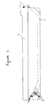
- the first method(figure 1) of the invention concerns a conductor or a system of conductors which is installed on avessel,starting from the bow near the water level and,through the double bottom, depending on the kind of the vessel,it finishes at the aft end, taking into consideration the vessel's loading conditions.
- the invention may be put-practically- into application ,in accordance with the afore mentioned two(2) basic methods and according to the ship's dimensions and the shipowners' intentions.
- the first application method of the invention is presented in figure 1 and it shows the vessel's "1" side view .
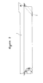
- the second method is presented in figure “2" and it shows a side view of the vessel “1" with the conductor or the system of conductors,in the area of the water level "2", which finishes(end s) at the bottom or the sides of the vessel and near the end of the boundary layer.
- the size of the conductor or system of conductors depends on the size and speed of the vessel.
- the invention can be applied at any,desirable,form,design or
- the construction of the invention is being realized by profile iron and steel plates , properly shaped to a conductor or to a system of conductors.- Their dimensions depend- proportionately- to the ship's dimensions and speed of propulsion ,being desired.
- ductor piece is not meant to be only the one of a circular section but that of any section and the transverse and the longitudinal(convergent or divergent).-
- the water pressure exercised on the bow of a vessel,during her movement is equalized-as much as possible -by being connected with the conductor or the system of the conductors by the-relatively-lower pressure( than that of the bow) ,being created at the aft end or at other locations of the vessel,taking into consideration the existence of the boundary layer.
- This shaping of the conductor may,also,be combined with the placing of a ring in front or on the propeller or propellers for having the water flow directed towards the propeller or propellers.-
- the conductor or the system of the conductors of the invention ends at the bottom or the sides of the vessel, the exis tence of the boundary layer is taken into consideration and the conductor or the system of the conductors will terminate near the end of the boundary layer.
Landscapes
- Chemical & Material Sciences (AREA)
- Engineering & Computer Science (AREA)
- Combustion & Propulsion (AREA)
- Mechanical Engineering (AREA)
- Ocean & Marine Engineering (AREA)
- Physics & Mathematics (AREA)
- Fluid Mechanics (AREA)
- Other Liquid Machine Or Engine Such As Wave Power Use (AREA)
Applications Claiming Priority (2)
| Application Number | Priority Date | Filing Date | Title |
|---|---|---|---|
| GR88100382 | 1988-06-15 | ||
| GR88010382 | 1988-06-15 |
Publications (1)
| Publication Number | Publication Date |
|---|---|
| EP0347363A1 true EP0347363A1 (fr) | 1989-12-20 |
Family
ID=10938759
Family Applications (1)
| Application Number | Title | Priority Date | Filing Date |
|---|---|---|---|
| EP89600011A Withdrawn EP0347363A1 (fr) | 1988-06-15 | 1989-05-15 | Dispositif pour diminuer la résistance à l'avancement d'un bateau |
Country Status (2)
| Country | Link |
|---|---|
| EP (1) | EP0347363A1 (fr) |
| GR (1) | GR880100382A (fr) |
Cited By (3)
| Publication number | Priority date | Publication date | Assignee | Title |
|---|---|---|---|---|
| GR920100376A (el) * | 1992-09-02 | 1994-05-31 | Emmanouil Petromanolakis | Βελτιώσεις σε αποσβεστήρες ενέργειας κυματισμού κατά την πρόωση ενός πλοίου. |
| AU663119B2 (en) * | 1992-10-19 | 1995-09-28 | Emmanuel E. Petromanolakis | Wave making energy absorber during vessel's propulsion |
| WO2010072052A1 (fr) * | 2008-12-25 | 2010-07-01 | Sun Zhiwei | Conduit de sillage pour navire |
Citations (5)
| Publication number | Priority date | Publication date | Assignee | Title |
|---|---|---|---|---|
| DE927256C (de) * | 1950-02-07 | 1955-05-02 | Erich Grund | Wellenschluckeranlage |
| DE1813611A1 (de) * | 1968-12-10 | 1970-07-02 | Dingedahl Carl Eduard | Wasserstromtunnel von Bug zum Heck mit Bugstromsteuerung und Beschleuniger |
| DE2234813A1 (de) * | 1972-07-13 | 1974-01-31 | Odawara Chuichiro | Schiffsrumpfkonstruktion |
| DE3628252A1 (de) * | 1986-08-20 | 1988-02-25 | Ludwig Dipl Ing Herbrand | Duesenantrieb fuer schiffe |
| EP0300977A1 (fr) * | 1987-05-29 | 1989-01-25 | Ferdinando Puccioni | Dispositif pour augmenter la vitesse des bateaux par diminution de la résistance à l'avance et bateaux en résultant |
-
1988
- 1988-06-15 GR GR880100382A patent/GR880100382A/el unknown
-
1989
- 1989-05-15 EP EP89600011A patent/EP0347363A1/fr not_active Withdrawn
Patent Citations (5)
| Publication number | Priority date | Publication date | Assignee | Title |
|---|---|---|---|---|
| DE927256C (de) * | 1950-02-07 | 1955-05-02 | Erich Grund | Wellenschluckeranlage |
| DE1813611A1 (de) * | 1968-12-10 | 1970-07-02 | Dingedahl Carl Eduard | Wasserstromtunnel von Bug zum Heck mit Bugstromsteuerung und Beschleuniger |
| DE2234813A1 (de) * | 1972-07-13 | 1974-01-31 | Odawara Chuichiro | Schiffsrumpfkonstruktion |
| DE3628252A1 (de) * | 1986-08-20 | 1988-02-25 | Ludwig Dipl Ing Herbrand | Duesenantrieb fuer schiffe |
| EP0300977A1 (fr) * | 1987-05-29 | 1989-01-25 | Ferdinando Puccioni | Dispositif pour augmenter la vitesse des bateaux par diminution de la résistance à l'avance et bateaux en résultant |
Non-Patent Citations (1)
| Title |
|---|
| PATENT ABSTRACTS OF JAPAN, vol. 8, no. 174 (M-316)[1611], 10th August 1984; & JP-A-59 67 191 (MURAKAMI ZOUSENSHIYO K.K.) 16-04-1984 * |
Cited By (3)
| Publication number | Priority date | Publication date | Assignee | Title |
|---|---|---|---|---|
| GR920100376A (el) * | 1992-09-02 | 1994-05-31 | Emmanouil Petromanolakis | Βελτιώσεις σε αποσβεστήρες ενέργειας κυματισμού κατά την πρόωση ενός πλοίου. |
| AU663119B2 (en) * | 1992-10-19 | 1995-09-28 | Emmanuel E. Petromanolakis | Wave making energy absorber during vessel's propulsion |
| WO2010072052A1 (fr) * | 2008-12-25 | 2010-07-01 | Sun Zhiwei | Conduit de sillage pour navire |
Also Published As
| Publication number | Publication date |
|---|---|
| GR880100382A (el) | 1990-05-11 |
Similar Documents
| Publication | Publication Date | Title |
|---|---|---|
| US6526903B2 (en) | High speed M-shaped boat hull | |
| US6250245B1 (en) | M-shaped boat hull | |
| JP6093039B2 (ja) | 船舶用推進システム | |
| CN2350310Y (zh) | 设有通水管道的增速船舶 | |
| GB2236717A (en) | Monohull fast sealift or semi-planing monohull ship | |
| US6314903B2 (en) | M-shaped boat hull | |
| EP0929439A1 (fr) | Amelioration apportee a des engins aquatiques avec helice ventilee | |
| WO2009126090A1 (fr) | Procédé pour équiper un navire d'une hélice à grand diamètre et navire équipé d'une hélice à grand diamètre | |
| US4843989A (en) | Ship's hull for small vessels and high speeds | |
| US5433161A (en) | SWAS vessel | |
| US4723928A (en) | Outboard engine bracing system | |
| EP0215985B1 (fr) | Système de propulsion d'un bateau | |
| WO1985005339A1 (fr) | Navire multicoque | |
| US5989082A (en) | Propulsion system for large ships | |
| US20020127925A1 (en) | Augmented thrust waterjet propulsor | |
| GB2055080A (en) | Propelling watercraft | |
| US20030154897A1 (en) | Waterjet propulsor for air lubricated ships | |
| EP0282462B1 (fr) | Dispositif de déchargement sous-marin des gaz d'échappement pour canot à moteur | |
| JP4842904B2 (ja) | 船舶の推進機構 | |
| CN216916186U (zh) | 一种船舶工程用可调式压浪板 | |
| US20090124145A1 (en) | Marine Drive System with Partially Submerged Propeller | |
| RU2013306C1 (ru) | Плавучее средство | |
| JPS62120292A (ja) | 船底部空気導入装置 | |
| SU1643309A1 (ru) | Речное судно | |
| KR20260007479A (ko) | 선박 추진스크류의 추진력 증강장치 |
Legal Events
| Date | Code | Title | Description |
|---|---|---|---|
| PUAI | Public reference made under article 153(3) epc to a published international application that has entered the european phase |
Free format text: ORIGINAL CODE: 0009012 |
|
| AK | Designated contracting states |
Kind code of ref document: A1 Designated state(s): BE CH DE ES FR GB IT LI NL SE |
|
| 17P | Request for examination filed |
Effective date: 19900419 |
|
| STAA | Information on the status of an ep patent application or granted ep patent |
Free format text: STATUS: THE APPLICATION IS DEEMED TO BE WITHDRAWN |
|
| 18D | Application deemed to be withdrawn |
Effective date: 19911203 |