EP0347562A2 - Soupape de sûreté - Google Patents
Soupape de sûreté Download PDFInfo
- Publication number
- EP0347562A2 EP0347562A2 EP89107714A EP89107714A EP0347562A2 EP 0347562 A2 EP0347562 A2 EP 0347562A2 EP 89107714 A EP89107714 A EP 89107714A EP 89107714 A EP89107714 A EP 89107714A EP 0347562 A2 EP0347562 A2 EP 0347562A2
- Authority
- EP
- European Patent Office
- Prior art keywords
- connection
- valve
- working
- channel
- tank
- Prior art date
- Legal status (The legal status is an assumption and is not a legal conclusion. Google has not performed a legal analysis and makes no representation as to the accuracy of the status listed.)
- Withdrawn
Links
Images

Classifications
-
- F—MECHANICAL ENGINEERING; LIGHTING; HEATING; WEAPONS; BLASTING
- F15—FLUID-PRESSURE ACTUATORS; HYDRAULICS OR PNEUMATICS IN GENERAL
- F15B—SYSTEMS ACTING BY MEANS OF FLUIDS IN GENERAL; FLUID-PRESSURE ACTUATORS, e.g. SERVOMOTORS; DETAILS OF FLUID-PRESSURE SYSTEMS, NOT OTHERWISE PROVIDED FOR
- F15B20/00—Safety arrangements for fluid actuator systems; Applications of safety devices in fluid actuator systems; Emergency measures for fluid actuator systems
- F15B20/001—Double valve requiring the use of both hands simultaneously
-
- Y—GENERAL TAGGING OF NEW TECHNOLOGICAL DEVELOPMENTS; GENERAL TAGGING OF CROSS-SECTIONAL TECHNOLOGIES SPANNING OVER SEVERAL SECTIONS OF THE IPC; TECHNICAL SUBJECTS COVERED BY FORMER USPC CROSS-REFERENCE ART COLLECTIONS [XRACs] AND DIGESTS
- Y10—TECHNICAL SUBJECTS COVERED BY FORMER USPC
- Y10T—TECHNICAL SUBJECTS COVERED BY FORMER US CLASSIFICATION
- Y10T137/00—Fluid handling
- Y10T137/8593—Systems
- Y10T137/87169—Supply and exhaust
- Y10T137/87193—Pilot-actuated
- Y10T137/87209—Electric
-
- Y—GENERAL TAGGING OF NEW TECHNOLOGICAL DEVELOPMENTS; GENERAL TAGGING OF CROSS-SECTIONAL TECHNOLOGIES SPANNING OVER SEVERAL SECTIONS OF THE IPC; TECHNICAL SUBJECTS COVERED BY FORMER USPC CROSS-REFERENCE ART COLLECTIONS [XRACs] AND DIGESTS
- Y10—TECHNICAL SUBJECTS COVERED BY FORMER USPC
- Y10T—TECHNICAL SUBJECTS COVERED BY FORMER US CLASSIFICATION
- Y10T137/00—Fluid handling
- Y10T137/8593—Systems
- Y10T137/87169—Supply and exhaust
- Y10T137/87217—Motor
- Y10T137/87225—Fluid motor
Definitions
- the invention relates to a hydraulically actuated 5/2-way safety valve, consisting of a valve housing with two valve bodies which can be moved in opposite directions in a bore in the housing, two e.g. Electromagnetically actuated pilot valves, a pump connection, two working connections and two tank connections, the valve bodies each having a working piston, which can be acted upon by the pressure medium via control channels and the pilot valves, and control pistons connected to the working piston, which have the connections between the pump connection, the working connections and control the tank connection.
- Safety valves of the aforementioned type are e.g. used to operate the brake and clutch of a mechanical press.
- a valve consists of two directional control valves, so that if one valve fails, the braking process is still guaranteed.
- the invention is based on the object of developing a safety valve of the type mentioned at the outset so that automatic monitoring of the valve is made possible without the use of special additional monitoring elements.
- the speed and pressure build-up at the consumer e.g. be controllable on a differential cylinder.
- each of the two valve bodies is formed from three axially spaced control pistons, through which, in conjunction with corresponding control edges in the housing in the basic position of the valve, the pump port P with the working port B and the working port A with the Tank connection R is connectable; through which, in the switching position of the valve, the pump connection P can be connected to the working connection A and the working connection B to the tank connection S; and by which finally, in the event of a malfunction, the pump connection P can be connected to the working connection B and the working connection A can be connected to the tank connection R.
- the safety valve is preferably coupled to a proportional three-way pressure reducing valve, one side of which is permanently connected to the tank connection S of the safety valve and the other side of which, depending on its switching position, can be connected to the connection R or the pump connection P of the safety valve.
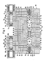
- a central bore 16 is formed in the housing, in which two valve bodies 18, 20 can be moved axially in opposite directions to one another.
- Each valve body is provided with a working piston 22, which has a blind bore, not designated in any more detail, in which a compression spring 24 is arranged and the two compression springs 24 seek to press the two valve bodies 18, 20 axially towards one another, in the basic position shown in FIG. 1 , in which the two pilot valves 12, 14 are not energized, the two The valve bodies 18, 20 abut one another with their end faces.
- the valve body 18 is provided with control pistons 26, 28, 30 and the valve body 20 is provided with control pistons 32, 34, 36.
- each of the working pistons 22 has a transverse bore 38, which connects the respective blind bore of the working piston to the space outside the working piston and opens into an annular groove 120 formed on the circumference of the respective working piston.
- the central bore 16 is provided with annular channels 78, 80, 82, 84 86, 88, 90, 92, 94, 96, and pockets 74, 76, 98 and 100, which are arranged at axial distances and lie in planes transverse to their axis.
- the ring channels and pockets together with the housing form control edges with which the aforementioned control pistons interact.
- the safety valve has a pump connection P, working connections A and B and tank connections R and S.
- a channel 40 runs from the pump connection P to a ring channel 122 of the central bore
- a channel 42 runs from the working connection A to the ring channel 94
- a channel 44 runs from the working connection B to the ring channel 90
- a channel 46 runs from the tank connection R to the ring channel 78
- a channel 48 extends from the tank connection S to an annular channel 124 of the central bore 16.
- branch channel 50 which opens into the ring channel 96 and two branch channels 52 branch off from the channel 40, one of which opens into the pocket 76 via an annular groove of the left working piston 22, while the other via an annular groove of the right Working piston 22 opens into the pocket 98.
- the ring channels 86 and 92 are connected by a connecting channel 54
- the ring channels 84 and 90 are connected by a connecting channel 56
- the ring channels 82 and 88 are connected by a connecting channel 58
- the ring channels 80, 94 are connected by a connecting channel 60 .
- the pilot valve 12 is provided with a piston 102 which can be moved axially back and forth in a bore in the valve housing. It is held in the basic position shown in FIG. 1 by compression springs 108, which are arranged in spring chambers 110, when the electromagnet 106 is not energized.
- the spring chambers 110 are constantly connected to one another via a connecting channel 112.
- the central bore is provided with annular channels 126, 128, 130 formed at axial intervals.
- the pilot valve 14 has a piston 104 which can be moved back and forth in an axial bore and which is held in the basic position shown in FIG. 1 by compression springs 114 which are arranged in spring chambers 116 when the electromagnet 106 is not excited.
- the two spring chambers 116 are constantly connected to one another via a connecting channel 118.
- the central bore is provided with annular channels 132, 134 and 136 formed at axial intervals.
- Control channels 62, 64, 66 and 68, 70, 72 are also formed in the housing of the safety valve, the control channel 62 leading from the pocket 74 to the ring channel 128 of the pilot valve 12; the control channel 64 leads from the pocket 76 to the ring channel 132 of the pilot valve 14; the control channel 66 leads from the ring channel 78 to the ring channel 126 of the pilot valve 12.
- the control channel 68 leads from the pocket 100 to the ring channel 134 of the pilot valve 14; the control channel 70 leads from pocket 98 to the ring channel 130 of the pilot valve 12 and the control channel 72 leads from the ring channel 96 to the ring channel 136 of the pilot valve 14.
- the safety valve according to the invention works as follows. 1 shows the basic position in which the two electromagnets 106 of the pilot valves 12, 14 are not energized.
- the left working piston 22 is supplied with the pump pressure by the inlet P via the right branch channel 52, the control channel 70, the pilot valve 12 and the control channel 62;
- the right working piston 22 is acted upon by the pump pressure via the left branch channel 52, the control channel 64, the pilot valve 14 and the control channel 68.
- these pressures cancel each other out and the two valve bodies 18, 20 are pressed together by their springs 24 until they meet with their end faces and the one shown in FIG.
- the pump connection P is connected to the channel 44 and thus to the working connection B via the channel 40, the ring channel 122, the ring channel 84, the connecting channel 56 and the ring channel 90.
- the working connection A is connected via the channel 42, the ring channel 94, the ring channel 96 and the branch channel 50 to the channel 46 and thus to the tank connection R (also also via 60, 80, 78 and 46).
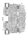
- the pilot valves 12 and 14 are activated, their magnets are energized and their pistons 102, 104 are switched to their switching position.
- the left-hand working piston 22 is connected via its transverse bore 38, the annular groove 120, the pocket 74, the control channel 62, the pilot valve 12, the control channel 66 and the annular groove 78 to the channel 46 and thus to the tank connection R.
- the right-hand working piston 22 is likewise connected to the tank connection R via its transverse bore 38, the annular groove 120, the pocket 100, the control channel 68, the pilot valve 14, the control channel 72, the annular channel 96 and the branch channel 50.
- the pump connection P is connected to the channel 42 and thus to the working connection A via the channel 40, the ring channels 122, 86, the connecting channel 54 and the ring channels 92, 94.
- the other working connection B is connected to the other tank connection S via the channel 44, the ring channel 90, the connecting channel 56, the ring channel 84, the ring channel 82, the connecting channel 58 and the ring channels 88 and 124.
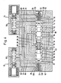
- FIG. 3 and 4 show two incorrect switching operations, the pilot valve 12 not switching in FIG. 3 while the pilot valve 14 switching, whereas in FIG. 4 the pilot valve 12 switched and the pilot valve 14 not switching.
- the pump connection P is connected to the working connection B, while the working connection A is connected to the tank connection R.
- the working connection B is connected to the pump connection P via the ring channels 90, 92, the connecting channel 54 and the ring channels 86, 122, while the working connection A via the ring channels 94, 96 and the branch channel 50 to the tank connection R is connected.
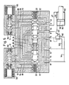
- FIG. 5 shows the safety valve according to the invention in the switching position coupled with a proportional three-way pressure reducing valve, hereinafter simply called “pressure reducing valve” for reasons of simplicity.
- the pressure reducing valve 140 is continuously connected to the tank connection 5 on one side via a line 49, while its other side, depending on the switching position, is connected via a line 142 to the pump connection P or via a line 144 to the tank connection R. can.
- the working connections A and B are connected to a consumer via lines 43, 45, e.g. to a differential cylinder 146 with piston 148, the line 43 leading from the working port A to the piston rod-side space 152 and the line 45 from the working port B to the cylinder-side space 150 of the differential cylinder 146.
- the safety valve is in the switch position, in which, as already stated above, the pump connection P is connected to the working connection A, while the working connection B is connected to the tank connection S.
- the direction of movement of the piston 148 can now be reversed and its speed can be controlled by appropriate adjustment of the pressure on the pressure reducing valve.
- the pressure medium flows, i.e. the oil, from the cylinder-side space 150 via B to S and from there via the pressure reducing valve 140 and the line 144 to the tank connection R.
- the full pump pressure prevails, so that the piston 148 moves to the left in FIG. 5.
- the secondary pressure on the pressure reducing valve is set to the pump pressure
- oil flows from the pump connection P via the line 142, the pressure reducing valve 140 and the tank connection S to the working connection B. Since the working connection A is still connected to the pump connection P, there is both in the cylinder side Space 150 as well as in the piston rod-side space 152 of the differential cylinder 146 the pump pressure, but since the piston face on the side of the space 150 is larger than the piston face on the side of the space 152 (because of the piston rod), the piston 148 moves to the right in FIG 5. The oil displaced in this way from space 152 flows out through A to P.
- the contact pressure can be adjusted by the pressure reducing valve 140, the contact pressure to the right being maximum when the pump pressure is at the working connection B, while the contact pressure to the left is maximum when the working connection 8 is connected via the connection 5 and ' the pressure reducing valve 140 to the tank connection R is fully relieved.
- the piston 148 then runs to the right as far as it will go, since with every faulty switching, as already explained above, the working connection A is relieved to the tank connection R, while the working connection B is connected to the pump connection P.
Landscapes
- Engineering & Computer Science (AREA)
- Chemical & Material Sciences (AREA)
- Analytical Chemistry (AREA)
- Physics & Mathematics (AREA)
- Fluid Mechanics (AREA)
- Mechanical Engineering (AREA)
- General Engineering & Computer Science (AREA)
- Fluid-Pressure Circuits (AREA)
- Fluid-Driven Valves (AREA)
Applications Claiming Priority (2)
| Application Number | Priority Date | Filing Date | Title |
|---|---|---|---|
| DE3817122 | 1988-05-19 | ||
| DE3817122A DE3817122A1 (de) | 1988-05-19 | 1988-05-19 | Sicherheitsventil |
Publications (2)
| Publication Number | Publication Date |
|---|---|
| EP0347562A2 true EP0347562A2 (fr) | 1989-12-27 |
| EP0347562A3 EP0347562A3 (fr) | 1990-10-17 |
Family
ID=6354732
Family Applications (1)
| Application Number | Title | Priority Date | Filing Date |
|---|---|---|---|
| EP19890107714 Withdrawn EP0347562A3 (fr) | 1988-05-19 | 1989-04-27 | Soupape de sûreté |
Country Status (4)
| Country | Link |
|---|---|
| US (1) | US4903728A (fr) |
| EP (1) | EP0347562A3 (fr) |
| JP (1) | JPH0242289A (fr) |
| DE (1) | DE3817122A1 (fr) |
Cited By (1)
| Publication number | Priority date | Publication date | Assignee | Title |
|---|---|---|---|---|
| EP3091239A1 (fr) * | 2015-04-30 | 2016-11-09 | Hydac Fluidtechnik GmbH | Dispositif de securite |
Families Citing this family (7)
| Publication number | Priority date | Publication date | Assignee | Title |
|---|---|---|---|---|
| US6155293A (en) | 1996-12-16 | 2000-12-05 | Ross Operating Valve Company | Double valve with anti-tiedown capability |
| US6478049B2 (en) | 1996-12-16 | 2002-11-12 | Ross Operating Valve Company | Double valve with anti-tiedown capability |
| US5927324A (en) * | 1996-12-16 | 1999-07-27 | Ross Operating Valve Company | Cross flow with crossmirror and lock out capability valve |
| ES2278832T3 (es) | 2001-05-04 | 2007-08-16 | Ross Operating Valve Company | Sistema de control de valvulas. |
| US6619369B2 (en) * | 2001-08-08 | 2003-09-16 | Try Co., Ltd. | Process for producing a thin die-cast molded article of an aluminum material |
| WO2015004003A1 (fr) * | 2013-07-08 | 2015-01-15 | Norgren Gmbh | Soupape de sûreté |
| US9903396B2 (en) * | 2016-03-08 | 2018-02-27 | Caterpillar Inc. | Valve assembly |
Family Cites Families (6)
| Publication number | Priority date | Publication date | Assignee | Title |
|---|---|---|---|---|
| US3171435A (en) * | 1961-12-05 | 1965-03-02 | Parker Hannifin Corp | Solenoid operated valve assembly |
| DE1245665B (de) * | 1963-01-23 | 1967-07-27 | Erich Herion | Steuerventil |
| DE1284231B (de) * | 1965-01-15 | 1969-02-20 | Herion Erich | Steuereinrichtung mit zwei Steuerventilen |
| DE1750358B2 (de) * | 1968-04-24 | 1974-09-19 | Robert Bosch Gmbh, 7000 Stuttgart | Elektrohydraulische Steuereinrichtung |
| DD96321A1 (fr) * | 1971-12-16 | 1973-03-12 | ||
| DE3104957C2 (de) * | 1981-02-12 | 1986-12-04 | Herion-Werke Kg, 7012 Fellbach | Hydraulisch betätigbares Pressensicherheitsventil |
-
1988
- 1988-05-19 DE DE3817122A patent/DE3817122A1/de not_active Withdrawn
-
1989
- 1989-04-26 US US07/344,351 patent/US4903728A/en not_active Expired - Fee Related
- 1989-04-27 EP EP19890107714 patent/EP0347562A3/fr not_active Withdrawn
- 1989-05-18 JP JP1125496A patent/JPH0242289A/ja active Pending
Cited By (1)
| Publication number | Priority date | Publication date | Assignee | Title |
|---|---|---|---|---|
| EP3091239A1 (fr) * | 2015-04-30 | 2016-11-09 | Hydac Fluidtechnik GmbH | Dispositif de securite |
Also Published As
| Publication number | Publication date |
|---|---|
| EP0347562A3 (fr) | 1990-10-17 |
| DE3817122A1 (de) | 1989-11-30 |
| JPH0242289A (ja) | 1990-02-13 |
| US4903728A (en) | 1990-02-27 |
Similar Documents
| Publication | Publication Date | Title |
|---|---|---|
| DE2232857C2 (de) | Steuereinrichtung für ein hydraulisch angetriebenes Arbeitsgerät | |
| DE2309552A1 (de) | Sicherheitsrueckschlagventil | |
| DE2258853B2 (de) | Drei- oder mehrwegeventil in sitzbauweise | |
| DE3817120A1 (de) | Sicherheitsventil | |
| DE2333174C3 (de) | Hydraulisches Fahrzeugbremssystem | |
| DE2511986C2 (de) | Hydraulische Stelleinrichtung zum Steuern der Position eines Stellkolbens | |
| EP0284831A2 (fr) | Dispositif de commande hydraulique pour des groupes de consommateurs | |
| DE3104957C2 (de) | Hydraulisch betätigbares Pressensicherheitsventil | |
| DE3817122A1 (de) | Sicherheitsventil | |
| EP0628730B1 (fr) | Système hydraulique, particulièrement pour une presse plieuse | |
| EP0342409A2 (fr) | Soupape de sûreté | |
| DE3225132A1 (de) | Hydraulisches sicherheitsbremsventil | |
| DE2816212C2 (fr) | ||
| DE2801689C2 (de) | Steuerventileinrichtung | |
| CH509535A (de) | Sicherheitsventil für druckmittelbetriebene Vorrichtungen | |
| DE3519148C2 (fr) | ||
| DE3935756A1 (de) | Hydraulische anlage in einem kraftfahrzeug | |
| DE8612453U1 (de) | Sicherheitsventil | |
| DE2705674C3 (de) | Hydraulische Servomotoranlage | |
| EP0618372B1 (fr) | Dispositif hydraulique de commande avec au moins un clapet anti-retour piloté | |
| DE3736750C2 (fr) | ||
| DE4435339A1 (de) | Anordnung zur Ansteuerung eines hydraulisch betätigbaren Hauptventils | |
| DE8806587U1 (de) | Sicherheitsventil | |
| DE19535677A1 (de) | Einrichtung zur Steuerung eines hydraulischen Motors | |
| EP0005818B1 (fr) | Vanne à 3 voies à commande hydraulique |
Legal Events
| Date | Code | Title | Description |
|---|---|---|---|
| PUAI | Public reference made under article 153(3) epc to a published international application that has entered the european phase |
Free format text: ORIGINAL CODE: 0009012 |
|
| AK | Designated contracting states |
Kind code of ref document: A2 Designated state(s): CH DE FR GB IT LI SE |
|
| PUAL | Search report despatched |
Free format text: ORIGINAL CODE: 0009013 |
|
| AK | Designated contracting states |
Kind code of ref document: A3 Designated state(s): CH DE FR GB IT LI SE |
|
| 17P | Request for examination filed |
Effective date: 19901128 |
|
| 17Q | First examination report despatched |
Effective date: 19920302 |
|
| STAA | Information on the status of an ep patent application or granted ep patent |
Free format text: STATUS: THE APPLICATION IS DEEMED TO BE WITHDRAWN |
|
| 18D | Application deemed to be withdrawn |
Effective date: 19930304 |