EP0347867A2 - Système d'éclairage - Google Patents
Système d'éclairage Download PDFInfo
- Publication number
- EP0347867A2 EP0347867A2 EP89111250A EP89111250A EP0347867A2 EP 0347867 A2 EP0347867 A2 EP 0347867A2 EP 89111250 A EP89111250 A EP 89111250A EP 89111250 A EP89111250 A EP 89111250A EP 0347867 A2 EP0347867 A2 EP 0347867A2
- Authority
- EP
- European Patent Office
- Prior art keywords
- lighting system
- vertical support
- reflector
- light source
- area
- Prior art date
- Legal status (The legal status is an assumption and is not a legal conclusion. Google has not performed a legal analysis and makes no representation as to the accuracy of the status listed.)
- Granted
Links
- 230000008878 coupling Effects 0.000 claims description 11
- 238000010168 coupling process Methods 0.000 claims description 11
- 238000005859 coupling reaction Methods 0.000 claims description 11
- 238000005286 illumination Methods 0.000 claims description 5
- 238000009434 installation Methods 0.000 claims 1
- 230000001678 irradiating effect Effects 0.000 abstract 1
- 230000004313 glare Effects 0.000 description 4
- 230000000694 effects Effects 0.000 description 2
- 230000001771 impaired effect Effects 0.000 description 2
- 230000010354 integration Effects 0.000 description 2
- 230000006978 adaptation Effects 0.000 description 1
- 230000015572 biosynthetic process Effects 0.000 description 1
- 230000000295 complement effect Effects 0.000 description 1
- 238000010276 construction Methods 0.000 description 1
- 238000010616 electrical installation Methods 0.000 description 1
- 230000007774 longterm Effects 0.000 description 1
Images


Classifications
-
- F—MECHANICAL ENGINEERING; LIGHTING; HEATING; WEAPONS; BLASTING
- F21—LIGHTING
- F21V—FUNCTIONAL FEATURES OR DETAILS OF LIGHTING DEVICES OR SYSTEMS THEREOF; STRUCTURAL COMBINATIONS OF LIGHTING DEVICES WITH OTHER ARTICLES, NOT OTHERWISE PROVIDED FOR
- F21V7/00—Reflectors for light sources
- F21V7/0008—Reflectors for light sources providing for indirect lighting
- F21V7/0016—Reflectors for light sources providing for indirect lighting on lighting devices that also provide for direct lighting, e.g. by means of independent light sources, by splitting of the light beam, by switching between both lighting modes
-
- F—MECHANICAL ENGINEERING; LIGHTING; HEATING; WEAPONS; BLASTING
- F21—LIGHTING
- F21S—NON-PORTABLE LIGHTING DEVICES; SYSTEMS THEREOF; VEHICLE LIGHTING DEVICES SPECIALLY ADAPTED FOR VEHICLE EXTERIORS
- F21S2/00—Systems of lighting devices, not provided for in main groups F21S4/00 - F21S10/00 or F21S19/00, e.g. of modular construction
-
- F—MECHANICAL ENGINEERING; LIGHTING; HEATING; WEAPONS; BLASTING
- F21—LIGHTING
- F21S—NON-PORTABLE LIGHTING DEVICES; SYSTEMS THEREOF; VEHICLE LIGHTING DEVICES SPECIALLY ADAPTED FOR VEHICLE EXTERIORS
- F21S6/00—Lighting devices intended to be free-standing
- F21S6/002—Table lamps, e.g. for ambient lighting
- F21S6/003—Table lamps, e.g. for ambient lighting for task lighting, e.g. for reading or desk work, e.g. angle poise lamps
-
- F—MECHANICAL ENGINEERING; LIGHTING; HEATING; WEAPONS; BLASTING
- F21—LIGHTING
- F21V—FUNCTIONAL FEATURES OR DETAILS OF LIGHTING DEVICES OR SYSTEMS THEREOF; STRUCTURAL COMBINATIONS OF LIGHTING DEVICES WITH OTHER ARTICLES, NOT OTHERWISE PROVIDED FOR
- F21V14/00—Controlling the distribution of the light emitted by adjustment of elements
- F21V14/04—Controlling the distribution of the light emitted by adjustment of elements by movement of reflectors
-
- F—MECHANICAL ENGINEERING; LIGHTING; HEATING; WEAPONS; BLASTING
- F21—LIGHTING
- F21V—FUNCTIONAL FEATURES OR DETAILS OF LIGHTING DEVICES OR SYSTEMS THEREOF; STRUCTURAL COMBINATIONS OF LIGHTING DEVICES WITH OTHER ARTICLES, NOT OTHERWISE PROVIDED FOR
- F21V21/00—Supporting, suspending, or attaching arrangements for lighting devices; Hand grips
- F21V21/06—Bases for movable standing lamps; Fixing standards to the bases
-
- F—MECHANICAL ENGINEERING; LIGHTING; HEATING; WEAPONS; BLASTING
- F21—LIGHTING
- F21V—FUNCTIONAL FEATURES OR DETAILS OF LIGHTING DEVICES OR SYSTEMS THEREOF; STRUCTURAL COMBINATIONS OF LIGHTING DEVICES WITH OTHER ARTICLES, NOT OTHERWISE PROVIDED FOR
- F21V23/00—Arrangement of electric circuit elements in or on lighting devices
- F21V23/02—Arrangement of electric circuit elements in or on lighting devices the elements being transformers, impedances or power supply units, e.g. a transformer with a rectifier
-
- F—MECHANICAL ENGINEERING; LIGHTING; HEATING; WEAPONS; BLASTING
- F21—LIGHTING
- F21W—INDEXING SCHEME ASSOCIATED WITH SUBCLASSES F21K, F21L, F21S and F21V, RELATING TO USES OR APPLICATIONS OF LIGHTING DEVICES OR SYSTEMS
- F21W2131/00—Use or application of lighting devices or systems not provided for in codes F21W2102/00-F21W2121/00
- F21W2131/40—Lighting for industrial, commercial, recreational or military use
- F21W2131/402—Lighting for industrial, commercial, recreational or military use for working places
Definitions
- the invention relates to a lighting system, in particular for uniformly illuminating limited work surfaces, consisting of at least one light source and a reflector assigned to it.
- Known lighting systems usually do not allow individual adaptation of the lighting to the respective workplace, are often critical with regard to the glare required in computer workplaces and generally do not allow the position of the workplaces to be changed without impairing the lighting quality of the workplace concerned.
- the object of the invention is to provide a lighting system of the type specified in the preamble of claim 1 in such a way that an optimal, glare-free illumination of the respective workplace is achieved without the need for light planning that encompasses the entire entire space and thereby does not impair the usable area of the ar working area must be accepted.
- the lighting system should also be suitable for individualizing the individual workplace and its effectiveness should not be impaired even if changes have to be made in the respective position of the workplace.
- the reflector is designed as a large-area reflector that at least partially spans the respective work surface and is held on at least one vertical support, and that at least one light source that radiates against the large-area reflector is held on at least one vertical support in the area between the work surface and the large-area reflector is.
- the large-area reflector on the vertical support is designed to be adjustable with regard to the distance and / or the inclination to the work surface and, above all, its intrinsic curvature can also be changed is, so that in each case the desired uniformity of the work surface lighting and the desired brightness can be achieved, specifically for the respective workplace and independently of neighboring workplaces.
- the vertical support advantageously consists of individual sections which can be coupled and mutually fixed, these individual sections comprising support sections and supporting functional sections for light sources and ballasts can be combined as desired.
- the couplings between the individual sections are designed both as mechanically stable plug-in, latching or screw connections, and are preferably provided with electrical coupling units which inevitably ensure the necessary electrical connections when the mechanical coupling is carried out.
- the mechanical coupling can take place via conically interlocking elements, the electrical connection parts being arranged concentrically and the positive and non-positive connection between the two mechanical parts to be coupled being achieved via a screw sleeve.
- the electrical connection elements can be used in pin-sleeve form or in the form of concentric contact elements.
- a diagonal division can be provided in such a way that a mechanically stable triangular beam that absorbs all mechanical loads is combined with a likewise triangular receiving space for the electrical functional elements.
- the light source assigned to the large-area reflector is combined at the same time with at least one direct emitter, one direct light source or one light source delivering both direct light and indirect light via the large-area reflector.
- a separate additional light source which is also preferably held on the vertical support, can be used.
- the brightness is preferably selected so that direct light and reflected light have the same brightness on the work surface, thus ensuring the typical softness of the indirect light and the required absence of shadows on the entire work surface.
- Fig. 1 shows an example of a piece of work furniture a desk 1 with a work surface 2, which is illuminated by means of the individually adapted to this work surface 2 lighting system according to the invention in accordance with the respective requirements with indirect and direct light in an optimal way, since there are no disturbing structures and there is no shadow formation.
- the lighting system comprises a vertical support 3, which can be provided with a stable base, but is preferably coupled directly to the desk 1 via an interface connection unit, as well as a large area reflector 4 and one attached to the vertical support 3 Light source 5, which radiates against the large area reflector 4 at predeterminable angles.
- ballast 6 is required for the light source 5
- this ballast 6 is preferably designed as a separate unit, likewise held on the vertical support 3. This has the essential advantage that the ballast is not affected by the heat development of the light source, which is of particular importance for electronic ballasts and increases their long-term functionality.
- the large-area reflector 4 extends over a substantial part of the width of the working surface 2 and can be designed, for example, in the form of an acute-angled, curved sail, which is realized by means of a tensioning frame 10, which is covered with a suitable reflective material.
- the large area reflector 4 is preferably attached to the vertical column 3 by means of a lockable swivel or ball joint 7 and can be equipped with a suitable counterweight 8.
- the lockable joint 7 can be telescopically extendable for the height adjustment of the large-area reflector 4, but it is also possible to adjust the height by inserting an intermediate piece, since the vertical support 3 preferably consists of modular sections to be connected to one another, in particular to be screwed together, both of which only support function possessing individual sections are provided, as well as carrier sections in the form of functional units, such a functional unit comprising, for example, a light source or a ballast.
- the light source 5 can also be combined with a direct emitter 9, which is also optionally designed to be directional and enables additional small-area irradiation of the work surface with the brightness of the indirect light of corresponding brightness.
- a direct emitter 9 which is also optionally designed to be directional and enables additional small-area irradiation of the work surface with the brightness of the indirect light of corresponding brightness.
- Fig. 2 shows in a highly schematic manner a possible embodiment of a connection or interface unit 11, as it can be integrated in the manner of a standard unit in work furniture in the edge or corner area, so that a lighting system according to the invention can then be connected without difficulty and the required stability of the lighting system is ensured by the coupling with the work furniture.
- the interface unit 11 is shown in FIG. 2 in the left part in a first embodiment provided with a flange 18 and in the right part in a second flange-free embodiment for a pipe coupling.
- the tubular vertical support 3 is screwed to a coupling sleeve 12, and this coupling sleeve 12 has a conically tapering end which engages in a sleeve 20 which is complementary and is provided with either a flange 18 or an external screw thread and with respect to this sleeve 20 can be fixed by means of a clamping screw member 14.
- This clamping member 14 engages over an annular shoulder of the coupling sleeve 12 and in this way allows an extremely stable clamping fixation to be achieved by a simple screwing operation.
- the advantage of this construction is that the outer diameter of all visible cylindrical parts is the same, so that in the assembled state there is a harmonious connection of the respective vertical support 3 to the connection unit 11.
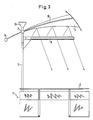
- the embodiment variant according to FIG. 3 differs from the embodiment according to FIG. 1 essentially in that the large-area reflector 4 is assigned a light source 5 in the form of a tube lamp, which extends over a substantial part of the width of the working surface 2 and possibly downwards can be shielded from the working surface 2 by a preferably adjustable screen.
- a light source 5 in the form of a tube lamp, which extends over a substantial part of the width of the working surface 2 and possibly downwards can be shielded from the working surface 2 by a preferably adjustable screen.
- an additional light source 16 for example in the form of a spotlight, can also be attached to the vertical support above the large area reflector 4 in order to obtain a defined room illumination independently of the individual workplace lighting guaranteed by the lighting system according to the invention.
- FIG. 4 shows a further embodiment of the invention, in which the light source 5 assigned to the large-area reflector 4 is spaced apart from the vertical support 3 and is designed such that a direct light source 17 can be effective approximately in the region of the center of the work surface 2.
- the direct light source 17 is preferably identical in terms of the light means used to the light source used to generate the indirect light, in which case a transparent area is provided on the work surface side, which is selected so that there is at least essentially on the work surface for the direct and indirect light gives the same brightness.
- a direct light source 15 which is preferably designed to be horizontal and / or pivotable in a vertical plane, can optionally or alternatively be integrated in the structure of the vertical support 3 consisting of individual sections can be used optionally without affecting the usable work surface 2.
Landscapes
- Engineering & Computer Science (AREA)
- General Engineering & Computer Science (AREA)
- Non-Portable Lighting Devices Or Systems Thereof (AREA)
- Preparation Of Compounds By Using Micro-Organisms (AREA)
- Circuit Arrangement For Electric Light Sources In General (AREA)
- Fastening Of Light Sources Or Lamp Holders (AREA)
- Lasers (AREA)
Applications Claiming Priority (2)
| Application Number | Priority Date | Filing Date | Title |
|---|---|---|---|
| DE3820926A DE3820926A1 (de) | 1988-06-21 | 1988-06-21 | Beleuchtungssystem |
| DE3820926 | 1988-06-21 |
Publications (3)
| Publication Number | Publication Date |
|---|---|
| EP0347867A2 true EP0347867A2 (fr) | 1989-12-27 |
| EP0347867A3 EP0347867A3 (en) | 1990-06-13 |
| EP0347867B1 EP0347867B1 (fr) | 1994-10-12 |
Family
ID=6356921
Family Applications (1)
| Application Number | Title | Priority Date | Filing Date |
|---|---|---|---|
| EP89111250A Expired - Lifetime EP0347867B1 (fr) | 1988-06-21 | 1989-06-20 | Système d'éclairage |
Country Status (4)
| Country | Link |
|---|---|
| US (1) | US4991065A (fr) |
| EP (1) | EP0347867B1 (fr) |
| AT (1) | ATE112837T1 (fr) |
| DE (2) | DE3820926A1 (fr) |
Cited By (4)
| Publication number | Priority date | Publication date | Assignee | Title |
|---|---|---|---|---|
| US5117343A (en) * | 1990-06-19 | 1992-05-26 | Siemens Aktiengesellschaft | Reflector arrangement |
| EP0675316A1 (fr) * | 1994-03-28 | 1995-10-04 | STATUS S.r.L. | Lampe de bureau ou lampadaire à éclairage de haute qualité |
| WO1998045644A1 (fr) * | 1997-04-08 | 1998-10-15 | Gerhard Rehm | Dispositif d'eclairage |
| WO2001020225A1 (fr) * | 1999-09-10 | 2001-03-22 | Manfred Kluth | Appareil d'eclairage |
Families Citing this family (13)
| Publication number | Priority date | Publication date | Assignee | Title |
|---|---|---|---|---|
| JPH06511212A (ja) * | 1991-05-09 | 1994-12-15 | ヌ−テック アンド エンジニアリング インコーポレイテッド | 乗用車用の計器表示方法とシステム |
| US5595440A (en) * | 1992-01-14 | 1997-01-21 | Musco Corporation | Means and method for highly controllable lighting of areas or objects |
| US5402327A (en) * | 1992-01-14 | 1995-03-28 | Musco Corporation | Means and method for highly controllable lighting |
| US5519590A (en) * | 1992-01-14 | 1996-05-21 | Musco Corporation | Means and method for highly controllable lighting |
| US5647661A (en) * | 1992-01-14 | 1997-07-15 | Musco Corporation | High efficiency, highly controllable lighting apparatus and method |
| US5337221A (en) * | 1992-01-14 | 1994-08-09 | Musco Corporation | Means and method for highly controllable lighting |
| US6264342B1 (en) * | 1999-07-27 | 2001-07-24 | Vh Lichttechnische Spezialgerate Gmbh | Illuminating device |
| US7686482B2 (en) * | 2007-05-11 | 2010-03-30 | Ructurelab GmbH | Lamp with sail-like overhead element, preferably for improving acoustics, room formation, and indirect lighting of workplaces |
| USD595114S1 (en) | 2008-05-23 | 2009-06-30 | Steelcase Inc. | Bracket assembly |
| USD617485S1 (en) | 2008-05-23 | 2010-06-08 | Steelcase Inc. | Lamp housing |
| US10539278B2 (en) * | 2014-08-31 | 2020-01-21 | Abl Ip Holding, Llc | Luminaire for creating effective proximity lighting in a low ambient lighting environment |
| US10422504B2 (en) * | 2014-08-31 | 2019-09-24 | Abl Ip Holding, Llc | Luminaire for illuminating a task surface and providing additional diffuse proximity lighting |
| CN105042478B (zh) * | 2015-08-04 | 2019-05-17 | 漳州立达信光电子科技有限公司 | Led照明灯 |
Family Cites Families (4)
| Publication number | Priority date | Publication date | Assignee | Title |
|---|---|---|---|---|
| FR1299310A (fr) * | 1961-09-02 | 1962-07-20 | Appareil émetteur de radiations | |
| US3851164A (en) * | 1973-12-04 | 1974-11-26 | C Intrator | Umbrella light |
| US4524405A (en) * | 1983-09-08 | 1985-06-18 | Heard Charles M | Fan-shaped indirect lighting reflector |
| DE3416161A1 (de) * | 1984-05-02 | 1985-11-07 | Bitsch, Hans-Ulrich, Prof. Dipl.-Designer, 4000 Düsseldorf | Vorrichtung zur indirekten raumbeleuchtung |
-
1988
- 1988-06-21 DE DE3820926A patent/DE3820926A1/de not_active Withdrawn
-
1989
- 1989-06-20 EP EP89111250A patent/EP0347867B1/fr not_active Expired - Lifetime
- 1989-06-20 DE DE58908487T patent/DE58908487D1/de not_active Expired - Fee Related
- 1989-06-20 AT AT89111250T patent/ATE112837T1/de not_active IP Right Cessation
- 1989-06-21 US US07/369,106 patent/US4991065A/en not_active Expired - Fee Related
Cited By (4)
| Publication number | Priority date | Publication date | Assignee | Title |
|---|---|---|---|---|
| US5117343A (en) * | 1990-06-19 | 1992-05-26 | Siemens Aktiengesellschaft | Reflector arrangement |
| EP0675316A1 (fr) * | 1994-03-28 | 1995-10-04 | STATUS S.r.L. | Lampe de bureau ou lampadaire à éclairage de haute qualité |
| WO1998045644A1 (fr) * | 1997-04-08 | 1998-10-15 | Gerhard Rehm | Dispositif d'eclairage |
| WO2001020225A1 (fr) * | 1999-09-10 | 2001-03-22 | Manfred Kluth | Appareil d'eclairage |
Also Published As
| Publication number | Publication date |
|---|---|
| DE3820926A1 (de) | 1989-12-28 |
| EP0347867B1 (fr) | 1994-10-12 |
| EP0347867A3 (en) | 1990-06-13 |
| US4991065A (en) | 1991-02-05 |
| DE58908487D1 (de) | 1994-11-17 |
| ATE112837T1 (de) | 1994-10-15 |
Similar Documents
| Publication | Publication Date | Title |
|---|---|---|
| EP0347867A2 (fr) | Système d'éclairage | |
| DE2009698A1 (de) | Lampenhalterung, insbesondere zum Aus strahlen von Flutlicht dienendes Lampenge hause | |
| EP3555521B1 (fr) | Dispositif d'éclairage | |
| EP0735311A1 (fr) | Système d'éclairage intérieur | |
| EP0677697B1 (fr) | Appareil d'éclairage pour plan de travail | |
| DE10161468A1 (de) | Leuchte | |
| EP1208769A1 (fr) | Table | |
| WO1987006995A1 (fr) | Lampe | |
| DE4109189A1 (de) | Einrichtung zur indirekten beleuchtung | |
| DE8519706U1 (de) | Gegenstrahlerleuchte mit Leuchtstofflampe | |
| EP0739069B1 (fr) | Dispositif de raccordement combiné | |
| DE3830076A1 (de) | Leuchte | |
| EP0747543A1 (fr) | Support sanitaire | |
| DE8900441U1 (de) | Vorrichtung zur kombinierten indirekten und lichtgelenkten Raumbeleuchtung | |
| EP1045196A2 (fr) | Dispositif d'éclairage avec une structure porteuse | |
| DE3301277A1 (de) | Arbeitsplatzleuchte | |
| DE9413769U1 (de) | Lampe mit Reflektor | |
| DE29606616U1 (de) | Arbeitsplatte mit Beleuchtung | |
| DE810530C (de) | Traeger fuer Leuchtroehren | |
| EP0502435A2 (fr) | Cloison de douche avec un dispositif d'éclairage | |
| DE20009448U1 (de) | Beleuchtungsapparat | |
| DE8904015U1 (de) | Präsentationsvorrichtung | |
| DE744676C (de) | Rueckstrahlflaeche fuer Anzeigetafeln | |
| DE19957976C2 (de) | Spiegel mit aufgebauter Leuchte | |
| DE19513364A1 (de) | Beleuchtungssystem |
Legal Events
| Date | Code | Title | Description |
|---|---|---|---|
| PUAI | Public reference made under article 153(3) epc to a published international application that has entered the european phase |
Free format text: ORIGINAL CODE: 0009012 |
|
| AK | Designated contracting states |
Kind code of ref document: A2 Designated state(s): AT BE CH DE ES FR GB IT LI LU NL SE |
|
| PUAL | Search report despatched |
Free format text: ORIGINAL CODE: 0009013 |
|
| AK | Designated contracting states |
Kind code of ref document: A3 Designated state(s): AT BE CH DE ES FR GB IT LI LU NL SE |
|
| 17P | Request for examination filed |
Effective date: 19901207 |
|
| 17Q | First examination report despatched |
Effective date: 19930218 |
|
| GRAA | (expected) grant |
Free format text: ORIGINAL CODE: 0009210 |
|
| AK | Designated contracting states |
Kind code of ref document: B1 Designated state(s): AT BE CH DE ES FR GB IT LI LU NL SE |
|
| PG25 | Lapsed in a contracting state [announced via postgrant information from national office to epo] |
Ref country code: IT Free format text: LAPSE BECAUSE OF FAILURE TO SUBMIT A TRANSLATION OF THE DESCRIPTION OR TO PAY THE FEE WITHIN THE PRE;WARNING: LAPSES OF ITALIAN PATENTS WITH EFFECTIVE DATE BEFORE 2007 MAY HAVE OCCURRED AT ANY TIME BEFORE 2007. THE CORRECT EFFECTIVE DATE MAY BE DIFFERENT FROM THE ONE RECORDED.SCRIBED TIME-LIMIT Effective date: 19941012 Ref country code: NL Effective date: 19941012 Ref country code: ES Free format text: THE PATENT HAS BEEN ANNULLED BY A DECISION OF A NATIONAL AUTHORITY Effective date: 19941012 Ref country code: BE Effective date: 19941012 Ref country code: FR Effective date: 19941012 Ref country code: GB Effective date: 19941012 |
|
| REF | Corresponds to: |
Ref document number: 112837 Country of ref document: AT Date of ref document: 19941015 Kind code of ref document: T |
|
| REF | Corresponds to: |
Ref document number: 58908487 Country of ref document: DE Date of ref document: 19941117 |
|
| PG25 | Lapsed in a contracting state [announced via postgrant information from national office to epo] |
Ref country code: SE Effective date: 19950112 |
|
| EN | Fr: translation not filed | ||
| NLV1 | Nl: lapsed or annulled due to failure to fulfill the requirements of art. 29p and 29m of the patents act | ||
| GBV | Gb: ep patent (uk) treated as always having been void in accordance with gb section 77(7)/1977 [no translation filed] |
Effective date: 19941012 |
|
| PG25 | Lapsed in a contracting state [announced via postgrant information from national office to epo] |
Ref country code: LI Effective date: 19950630 Ref country code: LU Free format text: LAPSE BECAUSE OF NON-PAYMENT OF DUE FEES Effective date: 19950630 Ref country code: CH Effective date: 19950630 |
|
| PLBE | No opposition filed within time limit |
Free format text: ORIGINAL CODE: 0009261 |
|
| STAA | Information on the status of an ep patent application or granted ep patent |
Free format text: STATUS: NO OPPOSITION FILED WITHIN TIME LIMIT |
|
| 26N | No opposition filed | ||
| REG | Reference to a national code |
Ref country code: CH Ref legal event code: PL |
|
| PGFP | Annual fee paid to national office [announced via postgrant information from national office to epo] |
Ref country code: AT Payment date: 19970619 Year of fee payment: 9 |
|
| PG25 | Lapsed in a contracting state [announced via postgrant information from national office to epo] |
Ref country code: AT Free format text: LAPSE BECAUSE OF NON-PAYMENT OF DUE FEES Effective date: 19980620 |
|
| PGFP | Annual fee paid to national office [announced via postgrant information from national office to epo] |
Ref country code: DE Payment date: 19980812 Year of fee payment: 10 |
|
| PG25 | Lapsed in a contracting state [announced via postgrant information from national office to epo] |
Ref country code: DE Free format text: LAPSE BECAUSE OF NON-PAYMENT OF DUE FEES Effective date: 20000503 |