EP0347869A1 - Outil de coupe à moteur portable, notamment scie à chaîne ou cisaille à haies - Google Patents
Outil de coupe à moteur portable, notamment scie à chaîne ou cisaille à haies Download PDFInfo
- Publication number
- EP0347869A1 EP0347869A1 EP89111266A EP89111266A EP0347869A1 EP 0347869 A1 EP0347869 A1 EP 0347869A1 EP 89111266 A EP89111266 A EP 89111266A EP 89111266 A EP89111266 A EP 89111266A EP 0347869 A1 EP0347869 A1 EP 0347869A1
- Authority
- EP
- European Patent Office
- Prior art keywords
- handle
- housing
- axis
- cutting device
- locking
- Prior art date
- Legal status (The legal status is an assumption and is not a legal conclusion. Google has not performed a legal analysis and makes no representation as to the accuracy of the status listed.)
- Granted
Links
- 230000007246 mechanism Effects 0.000 claims description 11
- 210000000078 claw Anatomy 0.000 claims description 9
- 230000000295 complement effect Effects 0.000 claims description 2
- 230000008859 change Effects 0.000 description 7
- 230000008901 benefit Effects 0.000 description 3
- 239000002184 metal Substances 0.000 description 3
- 240000007182 Ochroma pyramidale Species 0.000 description 1
- 230000007797 corrosion Effects 0.000 description 1
- 238000005260 corrosion Methods 0.000 description 1
- 230000008878 coupling Effects 0.000 description 1
- 238000010168 coupling process Methods 0.000 description 1
- 238000005859 coupling reaction Methods 0.000 description 1
- 230000007613 environmental effect Effects 0.000 description 1
- 210000003811 finger Anatomy 0.000 description 1
- 239000000463 material Substances 0.000 description 1
- 238000000034 method Methods 0.000 description 1
- 230000008569 process Effects 0.000 description 1
- 230000035939 shock Effects 0.000 description 1
- 210000003813 thumb Anatomy 0.000 description 1
Images

Classifications
-
- A—HUMAN NECESSITIES
- A01—AGRICULTURE; FORESTRY; ANIMAL HUSBANDRY; HUNTING; TRAPPING; FISHING
- A01G—HORTICULTURE; CULTIVATION OF VEGETABLES, FLOWERS, RICE, FRUIT, VINES, HOPS OR SEAWEED; FORESTRY; WATERING
- A01G3/00—Cutting implements specially adapted for horticultural purposes; Delimbing standing trees
- A01G3/04—Apparatus for trimming hedges, e.g. hedge shears
- A01G3/047—Apparatus for trimming hedges, e.g. hedge shears portable
- A01G3/053—Apparatus for trimming hedges, e.g. hedge shears portable motor-driven
- A01G3/0535—Apparatus for trimming hedges, e.g. hedge shears portable motor-driven with rotatable knives
-
- B—PERFORMING OPERATIONS; TRANSPORTING
- B27—WORKING OR PRESERVING WOOD OR SIMILAR MATERIAL; NAILING OR STAPLING MACHINES IN GENERAL
- B27B—SAWS FOR WOOD OR SIMILAR MATERIAL; COMPONENTS OR ACCESSORIES THEREFOR
- B27B17/00—Chain saws; Equipment therefor
- B27B17/0008—Means for carrying the chain saw, e.g. handles
-
- Y—GENERAL TAGGING OF NEW TECHNOLOGICAL DEVELOPMENTS; GENERAL TAGGING OF CROSS-SECTIONAL TECHNOLOGIES SPANNING OVER SEVERAL SECTIONS OF THE IPC; TECHNICAL SUBJECTS COVERED BY FORMER USPC CROSS-REFERENCE ART COLLECTIONS [XRACs] AND DIGESTS
- Y10—TECHNICAL SUBJECTS COVERED BY FORMER USPC
- Y10T—TECHNICAL SUBJECTS COVERED BY FORMER US CLASSIFICATION
- Y10T403/00—Joints and connections
- Y10T403/32—Articulated members
- Y10T403/32254—Lockable at fixed position
- Y10T403/32262—At selected angle
- Y10T403/32311—Ball and socket
Definitions
- the invention relates to a portable, motor-driven cutting device, in particular a chain saw or hedge trimmer, with a housing, on the rear section of which handle and operating elements are arranged, and on the front section of which cutting elements are arranged and at least one handle is articulated, rotatably or pivotably articulated about a first axis , which runs essentially parallel to the cutting plane and serves to adjust the cutting plane.
- a rear handle is provided, on which actuators for switching the saw on and off are arranged.
- the chain saw has a further front handle (handle), which is designed as an essentially L-shaped bracket and is parallel to the longitudinal axis of the device Lockable axis is pivotally hinged to the housing.
- the lock To change the cutting position of the sword or saw blade of the chain saw, the lock must be released. This is done according to the known design, in that an unlocking lever is actuated on the handle leg of the front carrying handle to release the pivoting lock between the pivoting carrying handle and the housing.
- the swivel lock is designed in the form of a resiliently biased locking claw, which ver ver in a fixed to the housing bound lock washer engages.
- the locking claw can be retracted from the engaged position into the toothed disk by actuating the unlocking lever, with which it is connected via a cable pull, so that the locking mechanism is released and the housing and carrying handle can be pivoted relative to one another in order to be able to bring about a change in the cutting plane.
- the invention is therefore based on the object of providing a cutting device of the type mentioned at the outset which is distinguished by convenient operability and high operational reliability and safety.
- a cutting device which has the features mentioned at the outset and is characterized in that the carrying handle and / or the housing about at least one further axis running essentially perpendicular to the cutting plane are pivotably articulated that the locking for the rotational or pivoting position with respect to the first axis is closed when opposite catches and counter-catches of the handle and housing have come into positive and / or frictional engagement with one another due to pivoting about the further axis.
- the invention provides a cutting device which can be guided by means of a rear handle and a front handle.
- the handle is attached to the housing and can be integrated into it or be made in one piece with it.
- the handle is rotatably and / or pivotally connected to the housing about a first axis and at least one further axis.
- the first rotary or swivel axis fulfills the function of being able to change the position of the cutting plane, for example the sword of a chainsaw.
- a lock is required which releasably fixes the rotational or swivel position with respect to the first axis.
- At least one further articulated connection of the handle with the housing is used, which has axes of rotation which run essentially perpendicular to the cutting plane, and around which housing and handle can be pivoted towards and away from one another. This pivoting about this further axis (s) essentially serves to close or open the locking device.
- the handle and / or the housing are arranged so as to be pivotable about the further axis by means of a rubber element as a hinge point.
- the rubber element can, for example, form a vertically extending section of an L-shaped handle.
- the locking can then be opened by manually pushing the carrying handle away from the housing. Due to the elastic properties of the rubber element, the locking mechanism closes again when the manual pressure force ceases to exist.
- articulation points between the handle and the housing can be provided.
- a joint device is suitable, for example a ball joint or a self-aligning ball bearing, which are arranged for the pivotable connection of the housing and the handle.
- ball joints enable swiveling movements around all three axes of rotation that are perpendicular to each other.
- the carrying handle can be rotated relative to the housing, the axis of rotation running parallel to the cutting plane.
- the self-aligning ball bearing enables swivel movements to a limited extent around at least one other axis, which runs through the center of the bearing and perpendicular to the cutting plane. Such swiveling movements can be sufficient to open or close appropriately designed detents with respect to the axis of rotation.
- locking within the scope of the invention.
- it can consist of a toothing fastened to the housing and encircling the first pivot axis like a circular path, and at least one claw fastened to the handle, which comes into engagement with the toothing when the handle is pivoted toward the housing and / or vice versa about the further axis.
- Another alternative is to implement locking by means of two rubber coverings, each attached to the handle and the housing, which have profiled outer surfaces - like tire profiles. When the handle or the housing is pivoted accordingly about the further axis, the outer surfaces can come into frictional engagement with one another.
- the safety of the cutting and sawing operation is served by a return spring between the handle and Arrange the housing in such a way that it counteracts the pivoting of the housing away from the handle and / or vice versa about the said further pivot axis.
- the user of the device who wants to change the cutting plane can, for example, release the locking mechanism and jerkily adjust the cutting plane by swiveling the handle away from the housing while simultaneously deflecting the return spring. Then the handle is automatically brought back to the housing by the return spring, so that the locking located between them is closed again.
- a further embodiment of the invention serves to increase the operational reliability and service life, according to which the handle or housing has a support shoulder for a protrusion which is directed towards the housing or handle and which is designed accordingly on the housing or handle and rests with the locking mechanism closed. This serves to relieve the articulation points for the mentioned axes of rotation and swivel from the weight of the device. Otherwise, if the device were to be held away from the floor by the user by the handle of the housing and by the handle attached to it, the weight of the device would bear on the articulation points, which would increase their frequency of failure.
- the articulation or articulation points can be simple and inexpensive.
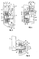
- the sword 2 of the motor chain saw is held on the end wall of the housing 1.
- a handle 3 is formed on the rear wall of the housing 1, on which - for the holding hand - operating elements 4, 5 are arranged.
- a front handle 6 with a handle 7 formed thereon is provided opposite the end wall of the housing 1 and adjacent to the sword 2.
- the handle 7 leads to an articulation point 8, via which the handle 6 is pivotably articulated on the housing 1.
- the articulation point is realized by means of a ball-and-socket joint which swivels the handle 6 both about a first axis of rotation or swivel axis 9 running parallel to the cutting plane of the sword 2 and about the other axes perpendicular thereto standing rotation axes 10 and 11 allows.
- the first axis of rotation or swivel axis 9 enables the handle 6 to be pivoted by the angle c (see FIG. 2), which is mainly used to adjust the cutting plane of the sword 2.
- a locking device 12 is arranged in the vicinity of the articulation point 8.
- this consists of a pair of notches / counter-notches located above the first axis 9 and a further pair of notches / counter-notches arranged below the axis.
- the upper pair is formed from a toothed ring 13 fixed in place on the end wall of the housing 1 and an opposing locking claw 14 which is formed in the lower end region of the handle 7 of the handle 6 surrounding the articulation point 8.
- the pair below the first pivot axis 9 is essentially formed of a rubber covering 15 which is attached to the lower edge of the handle 7, and a largely flush metal disc 16 which projects from the end wall of the housing 1 in the direction of the rubber covering 15.
- the rubber covering 15 comes into largely frictional engagement on the metal disk 16. This frictional engagement causes a fixation and thus locking of the rotational or pivoting position of the handling / handle 6 about the first axis 9.
- the use of the rubber covering 15 also achieves the additional advantage that at the moment of its stop on the metal disc 16, the resulting shock is elastically damped and thus the operator's hand holding the handle 6 is relieved.
- the inner ring 18 can be pivoted about the center of the bearing relative to the outer ring 21.
- the upper detent / counter detent pair 13, 14 corresponds to that explained with reference to FIGS. 1 and 2.
- the lower detent / counter-detent pair is designed differently from that shown in FIGS. 1 and 2 as follows: on the lower edge of the stem 7 of the The handle is fixed with a shock-absorbing rubber element 15a which, when pivoted in the direction of the angle a, strikes a bumper block 16a formed on the end wall of the housing.
- the width with which the bumper block 16a projects in the direction of the rubber element 15a may be adjustable; it can thereby be achieved that the angle a, in the direction of which the handle can be pivoted forward, is not too large.
- a separate articulation point 8a is provided for the first axis of rotation or swivel axis 9 and a separate articulation point 8b for the further swivel axes 10, 11.
- the first-mentioned articulation point 8a is realized by means of a deep groove ball bearing 23, which only enables rotation about the first axis 9.
- the deep groove ball bearing 23 is attached to an extension 24 which projects from a rubber block 25 and is integrally formed thereon.
- the rubber block 25 forms the second, separate articulation point 8b, by means of which the handle 7 of the handle can be pivoted forwards or backwards in the direction of the angle a or b.
- the locking / counter-locking pair 13, 14 arranged above the first pivot axis 9 corresponds to that shown in FIGS. 1 to 3.
- a support shoulder 28 is formed on the lower, horizontally running edge 26 of the locking claw 14 and on the adjacent edge 27 of the handle 7, which protrudes horizontally when the handle is not locked in the direction of the housing end wall. If the handle is adjusted along the angle a, the underside surface 29 of the projecting ring gear 13 comes to rest on the top surface 30 of the rest shoulder 28. This swings away from the housing end wall tem handle - relief of the rubber joint 8b is achieved. Due to the elasticity of the rubber block 25 with which the joint 8b is realized, this joint made in this way always endeavors to maintain the center position or to bring it back again. It is therefore easier for the operator to reach the middle position.
- a pin 31 projects horizontally at the lower end of the stem 7 and extends into a recess 32 located in the end wall of the housing 1.
- a pendulum ball bearing 17 is positioned on the pin 31 and positioned approximately in the center. It performs essentially the same functions as that shown in FIG. 3.
- the free end of the extension 1 is provided with a spur gear toothing 33, which is surrounded by a complementary inner toothing 34 such that the spur gear toothing 33 comes into engagement with the inner wheel toothing 34 when pivoting in the direction of the angle a or b.
- the invention is not restricted to the exemplary embodiments described above.
- a form-locking locking means by means of a claw coupling or a perforated disc with axially or radially extending recesses, in which a bolt engages releasably.
- a friction locking with a disc brake or equivalent devices can also be used.
- the position of the projecting pin changes so that, for example, the position of the pin can be changed by means of spring force so that the locking mechanism leads to engagement of the above-mentioned catches and counter-catches with one another.
- the mechanism for effecting the locking can be implemented in a variety of ways, for example by means of a linkage or in an electromechanical manner by means of relays or electromagnetic coils.
Landscapes
- Life Sciences & Earth Sciences (AREA)
- Forests & Forestry (AREA)
- Biodiversity & Conservation Biology (AREA)
- Ecology (AREA)
- Environmental Sciences (AREA)
- Engineering & Computer Science (AREA)
- Mechanical Engineering (AREA)
- Wood Science & Technology (AREA)
- Sawing (AREA)
- Harvester Elements (AREA)
Priority Applications (1)
| Application Number | Priority Date | Filing Date | Title |
|---|---|---|---|
| AT89111266T ATE79717T1 (de) | 1988-06-23 | 1989-06-21 | Tragbares, motorgetriebenes schneidgeraet, insbesondere motorsaege, heckenschere od.dgl. |
Applications Claiming Priority (2)
| Application Number | Priority Date | Filing Date | Title |
|---|---|---|---|
| DE3821209 | 1988-06-23 | ||
| DE3821209A DE3821209A1 (de) | 1988-06-23 | 1988-06-23 | Tragbares, motorgetriebenes schneidgeraet, insbesondere motorsaege, heckenschere od. dgl. |
Publications (2)
| Publication Number | Publication Date |
|---|---|
| EP0347869A1 true EP0347869A1 (fr) | 1989-12-27 |
| EP0347869B1 EP0347869B1 (fr) | 1992-08-26 |
Family
ID=6357089
Family Applications (1)
| Application Number | Title | Priority Date | Filing Date |
|---|---|---|---|
| EP89111266A Expired - Lifetime EP0347869B1 (fr) | 1988-06-23 | 1989-06-21 | Outil de coupe à moteur portable, notamment scie à chaîne ou cisaille à haies |
Country Status (5)
| Country | Link |
|---|---|
| US (1) | US4974325A (fr) |
| EP (1) | EP0347869B1 (fr) |
| AT (1) | ATE79717T1 (fr) |
| CA (1) | CA1321078C (fr) |
| DE (2) | DE3821209A1 (fr) |
Cited By (5)
| Publication number | Priority date | Publication date | Assignee | Title |
|---|---|---|---|---|
| EP0622015A1 (fr) * | 1993-04-08 | 1994-11-02 | GARDENA Kress + Kastner GmbH | Cisaille à haies |
| WO1994026482A1 (fr) * | 1993-05-12 | 1994-11-24 | Reinhold Haertlein | Machine a couper motorisee, portative, notamment tronçonneuse ou machine similaire |
| US6050253A (en) * | 1997-06-25 | 2000-04-18 | Aktiebolaget Electrolux (Publ) | Hand-operated cutting machine |
| DE19926375A1 (de) * | 1999-06-10 | 2000-12-14 | Gardena Kress & Kastner Gmbh | Motorbetriebenes Gartenwerkzeug, insbesondere Heckenschere |
| US7392568B2 (en) * | 2004-04-01 | 2008-07-01 | Hilt Aktiengesellschaft | Hand-held power tool with an auxiliary handle |
Families Citing this family (19)
| Publication number | Priority date | Publication date | Assignee | Title |
|---|---|---|---|---|
| GB2390324A (en) * | 2002-06-19 | 2004-01-07 | Black & Decker Inc | Power tool with pivoting handle |
| DE4302676A1 (de) * | 1993-01-30 | 1994-08-04 | Bosch Gmbh Robert | Beidhändig geführtes Elektrohandwerkzeug mit Griffbügel |
| DE4422245A1 (de) * | 1994-06-24 | 1996-01-04 | Fraunhofer Ges Forschung | Bügelförmiger Vordergriff für handgeführte Geräte |
| DE4422247A1 (de) * | 1994-06-24 | 1996-01-04 | Fraunhofer Ges Forschung | Führungs- und Haltegriff für handgeführte Geräte |
| SE510335C2 (sv) * | 1995-09-20 | 1999-05-10 | Electrolux Ab | Motordriven häcksax |
| DE19640653A1 (de) * | 1996-10-02 | 1998-04-09 | Gardena Kress & Kastner Gmbh | Motorbetriebene Heckenschere |
| US6141876A (en) * | 1998-05-04 | 2000-11-07 | Emerson Electric Co. | Soil pipe cutter |
| US6736037B2 (en) * | 1999-03-22 | 2004-05-18 | Ethan Dean | Coping saw |
| DE10050696B4 (de) * | 2000-10-13 | 2014-12-24 | Andreas Stihl Ag & Co. | Handgeführtes Arbeitsgerät, insbesondere Hochentaster |
| ES2261795T3 (es) * | 2002-01-10 | 2006-11-16 | Black & Decker Inc. | Caja de engranajes. |
| DE10260466B4 (de) * | 2002-12-21 | 2014-07-03 | Andreas Stihl Ag & Co. Kg | Handgeführtes Arbeitsgerät |
| DE102004036420A1 (de) * | 2004-07-27 | 2006-03-23 | Hilti Ag | Werkzeuggerätehandgriff |
| DE102005058755A1 (de) * | 2005-12-05 | 2007-06-06 | Gardena Manufacturing Gmbh | Arbeitsgerät mit Griffeinheit |
| US8156656B2 (en) * | 2009-05-07 | 2012-04-17 | Black & Decker Inc. | Hedgetrimmer with rotatable rear handle |
| USD623909S1 (en) | 2009-10-30 | 2010-09-21 | Black & Decker Inc. | Hedgetrimmer with rotating handle |
| DE102010026575B4 (de) * | 2010-07-08 | 2012-01-19 | Mogatec Moderne Gartentechnik Gmbh | Handwerkzeugmaschine, insbesondere eine Heckenschere |
| WO2016127450A1 (fr) * | 2015-02-11 | 2016-08-18 | 杭州鲁茨科技有限公司 | Élagueuse |
| US12539639B2 (en) | 2022-04-18 | 2026-02-03 | Black & Decker Inc. | Chain saw |
| JP7904169B2 (ja) * | 2023-03-29 | 2026-08-12 | 株式会社やまびこ | ヘッジトリマー |
Citations (5)
| Publication number | Priority date | Publication date | Assignee | Title |
|---|---|---|---|---|
| US3375044A (en) * | 1967-05-04 | 1968-03-26 | Arnold M. Peterson | Handle adapter for tools |
| DE2440483A1 (de) * | 1973-08-29 | 1975-03-13 | Husqvarna Ab | Motorsaege |
| DE2909777A1 (de) * | 1979-03-13 | 1980-09-18 | Stihl Maschf Andreas | Motorkettensaege |
| DE2816485C2 (de) * | 1978-04-15 | 1983-09-08 | Reinhold 8531 Hagenbüchach Härtlein | Handgriffausbildung an einem tragbaren kraftbetriebenen Werkzeug, insbesondere Motorsäge, Heckenschere od. dgl. |
| EP0267472A1 (fr) * | 1986-11-06 | 1988-05-18 | Bengt Arvidsson | Moyens de préhension d'un outil portable à moteur |
Family Cites Families (8)
| Publication number | Priority date | Publication date | Assignee | Title |
|---|---|---|---|---|
| US2027560A (en) * | 1933-04-17 | 1936-01-14 | O & S Bearing Company | Self-lubricating, self-aligning bearing and method of forming same |
| US3567262A (en) * | 1969-05-02 | 1971-03-02 | Western Hydraulics Inc | Self-aligning double-ball joint |
| US4222680A (en) * | 1978-03-06 | 1980-09-16 | Browning Charles E | Variable position friction joint |
| US4353615A (en) * | 1978-07-03 | 1982-10-12 | Xerox Corporation | Dynamic mounting for holographic spinners |
| JPS604476A (ja) * | 1983-06-22 | 1985-01-10 | 株式会社加島サドル製作所 | 角度調節型サドル |
| US4767231A (en) * | 1984-01-05 | 1988-08-30 | Wallis Frederick A | Adjustable arm |
| US4708510A (en) * | 1986-04-17 | 1987-11-24 | Mcconnell Bernard E | Ball joint coupling |
| US4726118A (en) * | 1987-03-09 | 1988-02-23 | Ronald Mattson | Handle and skid assembly for a chain saw |
-
1988
- 1988-06-23 DE DE3821209A patent/DE3821209A1/de active Granted
-
1989
- 1989-06-21 DE DE8989111266T patent/DE58902130D1/de not_active Expired - Lifetime
- 1989-06-21 CA CA000603519A patent/CA1321078C/fr not_active Expired - Fee Related
- 1989-06-21 AT AT89111266T patent/ATE79717T1/de not_active IP Right Cessation
- 1989-06-21 EP EP89111266A patent/EP0347869B1/fr not_active Expired - Lifetime
- 1989-06-22 US US07/369,979 patent/US4974325A/en not_active Expired - Fee Related
Patent Citations (5)
| Publication number | Priority date | Publication date | Assignee | Title |
|---|---|---|---|---|
| US3375044A (en) * | 1967-05-04 | 1968-03-26 | Arnold M. Peterson | Handle adapter for tools |
| DE2440483A1 (de) * | 1973-08-29 | 1975-03-13 | Husqvarna Ab | Motorsaege |
| DE2816485C2 (de) * | 1978-04-15 | 1983-09-08 | Reinhold 8531 Hagenbüchach Härtlein | Handgriffausbildung an einem tragbaren kraftbetriebenen Werkzeug, insbesondere Motorsäge, Heckenschere od. dgl. |
| DE2909777A1 (de) * | 1979-03-13 | 1980-09-18 | Stihl Maschf Andreas | Motorkettensaege |
| EP0267472A1 (fr) * | 1986-11-06 | 1988-05-18 | Bengt Arvidsson | Moyens de préhension d'un outil portable à moteur |
Cited By (6)
| Publication number | Priority date | Publication date | Assignee | Title |
|---|---|---|---|---|
| EP0622015A1 (fr) * | 1993-04-08 | 1994-11-02 | GARDENA Kress + Kastner GmbH | Cisaille à haies |
| WO1994026482A1 (fr) * | 1993-05-12 | 1994-11-24 | Reinhold Haertlein | Machine a couper motorisee, portative, notamment tronçonneuse ou machine similaire |
| US5640773A (en) * | 1993-05-12 | 1997-06-24 | Haertlein; Reinhold | Portable motor-driven cutting tool, particularly a power saw or the like |
| US6050253A (en) * | 1997-06-25 | 2000-04-18 | Aktiebolaget Electrolux (Publ) | Hand-operated cutting machine |
| DE19926375A1 (de) * | 1999-06-10 | 2000-12-14 | Gardena Kress & Kastner Gmbh | Motorbetriebenes Gartenwerkzeug, insbesondere Heckenschere |
| US7392568B2 (en) * | 2004-04-01 | 2008-07-01 | Hilt Aktiengesellschaft | Hand-held power tool with an auxiliary handle |
Also Published As
| Publication number | Publication date |
|---|---|
| US4974325A (en) | 1990-12-04 |
| CA1321078C (fr) | 1993-08-10 |
| EP0347869B1 (fr) | 1992-08-26 |
| DE3821209A1 (de) | 1989-12-28 |
| DE58902130D1 (de) | 1992-10-01 |
| ATE79717T1 (de) | 1992-09-15 |
| DE3821209C2 (fr) | 1991-09-05 |
Similar Documents
| Publication | Publication Date | Title |
|---|---|---|
| EP0347869B1 (fr) | Outil de coupe à moteur portable, notamment scie à chaîne ou cisaille à haies | |
| EP3792009B1 (fr) | Appareil de travail portatif doté d'un outil | |
| DE69405655T2 (de) | Kappsäge mit Parallelogramkonstruktion | |
| DE19637874B4 (de) | Heckenschneider mit Motorantrieb | |
| DE2854369C2 (de) | Kreissäge mit Spaltkeil | |
| DE9018178U1 (de) | Handgeführtes Arbeitsgerät | |
| DE3811170A1 (de) | Schutzvorrichtungsbewegungssystem in einer zertrennvorrichtung | |
| DE60003245T2 (de) | Arretiervorrichtung für Tischsägeschutzvorrichtung | |
| DE3924440A1 (de) | Bedienungsvorrichtung fuer einen von hand gefuehrten rasenmaeher | |
| DE2546017C2 (de) | Bremsvorrichtung für eine tragbare Motorkettensäge | |
| EP1479321B1 (fr) | Meuble d'assise avec repose-pied pivotant vers l'extérieur | |
| DE2621812C2 (de) | Sicherheitsbremse zum Abbremsen der Sägekette bei einer tragbaren Motorkettensäge | |
| EP1368156A1 (fr) | Machine a main dotee d'un capot pivotant de couverture de l'outil | |
| DE69301798T2 (de) | Schwenkbarer Tisch mit Motorwerkzeug | |
| DE60210218T2 (de) | Gehrungssäge | |
| EP1454695A2 (fr) | Cisaille | |
| EP2560557B1 (fr) | Dispositif de traction d'un dispositif de rétraction chirurgical | |
| DE2909777A1 (de) | Motorkettensaege | |
| DE4026012A1 (de) | Fahrsteuerung fuer geraete | |
| EP2250006B1 (fr) | Scie circulaire à réglage d'inclinaison | |
| DE3324628A1 (de) | Kettenbrems-vorrichtung | |
| EP0440827B1 (fr) | Dispositif de freinage pour une scie à main motorisée, en particulier une scie à chaîne | |
| DE102019101787A1 (de) | Wippsäge | |
| DE2747933C3 (de) | Sicherheitsgurtbefestigung | |
| EP2277674B1 (fr) | Machine-outil, en particulier dispositif de sciage |
Legal Events
| Date | Code | Title | Description |
|---|---|---|---|
| PUAI | Public reference made under article 153(3) epc to a published international application that has entered the european phase |
Free format text: ORIGINAL CODE: 0009012 |
|
| AK | Designated contracting states |
Kind code of ref document: A1 Designated state(s): AT CH DE FR LI SE |
|
| 17P | Request for examination filed |
Effective date: 19900410 |
|
| 17Q | First examination report despatched |
Effective date: 19910920 |
|
| GRAA | (expected) grant |
Free format text: ORIGINAL CODE: 0009210 |
|
| AK | Designated contracting states |
Kind code of ref document: B1 Designated state(s): AT CH DE FR LI SE |
|
| REF | Corresponds to: |
Ref document number: 79717 Country of ref document: AT Date of ref document: 19920915 Kind code of ref document: T |
|
| REF | Corresponds to: |
Ref document number: 58902130 Country of ref document: DE Date of ref document: 19921001 |
|
| ET | Fr: translation filed | ||
| PLBE | No opposition filed within time limit |
Free format text: ORIGINAL CODE: 0009261 |
|
| STAA | Information on the status of an ep patent application or granted ep patent |
Free format text: STATUS: NO OPPOSITION FILED WITHIN TIME LIMIT |
|
| 26N | No opposition filed | ||
| EAL | Se: european patent in force in sweden |
Ref document number: 89111266.6 |
|
| PGFP | Annual fee paid to national office [announced via postgrant information from national office to epo] |
Ref country code: AT Payment date: 19980624 Year of fee payment: 10 |
|
| PGFP | Annual fee paid to national office [announced via postgrant information from national office to epo] |
Ref country code: SE Payment date: 19980625 Year of fee payment: 10 |
|
| PGFP | Annual fee paid to national office [announced via postgrant information from national office to epo] |
Ref country code: FR Payment date: 19980629 Year of fee payment: 10 |
|
| PGFP | Annual fee paid to national office [announced via postgrant information from national office to epo] |
Ref country code: CH Payment date: 19980724 Year of fee payment: 10 |
|
| PG25 | Lapsed in a contracting state [announced via postgrant information from national office to epo] |
Ref country code: AT Free format text: LAPSE BECAUSE OF NON-PAYMENT OF DUE FEES Effective date: 19990621 |
|
| PG25 | Lapsed in a contracting state [announced via postgrant information from national office to epo] |
Ref country code: SE Free format text: THE PATENT HAS BEEN ANNULLED BY A DECISION OF A NATIONAL AUTHORITY Effective date: 19990629 |
|
| PG25 | Lapsed in a contracting state [announced via postgrant information from national office to epo] |
Ref country code: LI Free format text: LAPSE BECAUSE OF NON-PAYMENT OF DUE FEES Effective date: 19990630 Ref country code: FR Free format text: THE PATENT HAS BEEN ANNULLED BY A DECISION OF A NATIONAL AUTHORITY Effective date: 19990630 Ref country code: CH Free format text: LAPSE BECAUSE OF NON-PAYMENT OF DUE FEES Effective date: 19990630 |
|
| REG | Reference to a national code |
Ref country code: CH Ref legal event code: PL |
|
| EUG | Se: european patent has lapsed |
Ref document number: 89111266.6 |
|
| REG | Reference to a national code |
Ref country code: FR Ref legal event code: ST |
|
| PGFP | Annual fee paid to national office [announced via postgrant information from national office to epo] |
Ref country code: DE Payment date: 20020328 Year of fee payment: 13 |
|
| PG25 | Lapsed in a contracting state [announced via postgrant information from national office to epo] |
Ref country code: DE Free format text: LAPSE BECAUSE OF NON-PAYMENT OF DUE FEES Effective date: 20030101 |