EP0348304A2 - Sicherheits- und Regulierventil für Gas - Google Patents
Sicherheits- und Regulierventil für Gas Download PDFInfo
- Publication number
- EP0348304A2 EP0348304A2 EP89401792A EP89401792A EP0348304A2 EP 0348304 A2 EP0348304 A2 EP 0348304A2 EP 89401792 A EP89401792 A EP 89401792A EP 89401792 A EP89401792 A EP 89401792A EP 0348304 A2 EP0348304 A2 EP 0348304A2
- Authority
- EP
- European Patent Office
- Prior art keywords
- housing
- safety
- valves
- gas
- valve
- Prior art date
- Legal status (The legal status is an assumption and is not a legal conclusion. Google has not performed a legal analysis and makes no representation as to the accuracy of the status listed.)
- Granted
Links
Images

Classifications
-
- F—MECHANICAL ENGINEERING; LIGHTING; HEATING; WEAPONS; BLASTING
- F23—COMBUSTION APPARATUS; COMBUSTION PROCESSES
- F23D—BURNERS
- F23D14/00—Burners for combustion of a gas, e.g. of a gas stored under pressure as a liquid
- F23D14/46—Details
-
- F—MECHANICAL ENGINEERING; LIGHTING; HEATING; WEAPONS; BLASTING
- F23—COMBUSTION APPARATUS; COMBUSTION PROCESSES
- F23N—REGULATING OR CONTROLLING COMBUSTION
- F23N5/00—Systems for controlling combustion
- F23N5/26—Details
-
- F—MECHANICAL ENGINEERING; LIGHTING; HEATING; WEAPONS; BLASTING
- F24—HEATING; RANGES; VENTILATING
- F24H—FLUID HEATERS, e.g. WATER OR AIR HEATERS, HAVING HEAT-GENERATING MEANS, e.g. HEAT PUMPS, IN GENERAL
- F24H15/00—Control of fluid heaters
- F24H15/30—Control of fluid heaters characterised by control outputs; characterised by the components to be controlled
- F24H15/305—Control of valves
- F24H15/31—Control of valves of valves having only one inlet port and one outlet port, e.g. flow rate regulating valves
-
- F—MECHANICAL ENGINEERING; LIGHTING; HEATING; WEAPONS; BLASTING
- F24—HEATING; RANGES; VENTILATING
- F24H—FLUID HEATERS, e.g. WATER OR AIR HEATERS, HAVING HEAT-GENERATING MEANS, e.g. HEAT PUMPS, IN GENERAL
- F24H9/00—Details
- F24H9/20—Arrangement or mounting of control or safety devices
- F24H9/2007—Arrangement or mounting of control or safety devices for water heaters
- F24H9/2035—Arrangement or mounting of control or safety devices for water heaters using fluid fuel
-
- F—MECHANICAL ENGINEERING; LIGHTING; HEATING; WEAPONS; BLASTING
- F23—COMBUSTION APPARATUS; COMBUSTION PROCESSES
- F23N—REGULATING OR CONTROLLING COMBUSTION
- F23N2235/00—Valves, nozzles or pumps
- F23N2235/12—Fuel valves
- F23N2235/14—Fuel valves electromagnetically operated
-
- F—MECHANICAL ENGINEERING; LIGHTING; HEATING; WEAPONS; BLASTING
- F23—COMBUSTION APPARATUS; COMBUSTION PROCESSES
- F23N—REGULATING OR CONTROLLING COMBUSTION
- F23N2235/00—Valves, nozzles or pumps
- F23N2235/12—Fuel valves
- F23N2235/18—Groups of two or more valves
Definitions
- the present invention relates to a safety and regulation device for supplying gas to a burner, to a gas-heated appliance and in particular to a boiler, a water heater, starting on arrival. gas main and ending at the burner injectors.
- the object of the invention is to reduce the cost and increase the reliability of the gas supply devices, thanks to a design involving few parts.
- the subject of the invention is a device forming a multifunctional gas valve, comprising a housing which can be produced from an aluminum profile and which makes it possible to combine the safety, regulation and gas distribution functions. to the injectors.
- This box can receive the control panel of the device on its upper face or on a side face and has two grooves in its upper part allowing to carry the control circuits of safety and regulation valves.
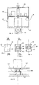
- the housing consists of a part 4 and a cover 29.
- the one-piece part 4 is produced from an aluminum profile cut to length and comprises two parallel conduits 5 and 6 partitioned by watertight plugs 9, 10, 11, 12 and 13, in order to obtain the safety chamber 14 , the intermediate chamber 15, the regulation chamber 16 and the distribution chamber 17 (feeder).
- the cover 29 has grooves 3 for mounting an electronic card 30 carrying the control circuits of the various valves and carries on its upper face the control panel 36 of the device with, in particular, the operating buttons 31.
- the gas arrives through the connector 8 and enters the chamber 14 where the safety valve 7 controlled by the safety valve 20 is located, this valve being in the closed position when the appliance is stopped or in safety and in the open position when the the device is operating normally.
- the gas penetrates, through the orifice 18, into the chamber 15, then, through the orifice 19, into the chamber 16 where the regulating valves 21 and 22 are located, actuated respectively by the valves 23 and 24, these being in the open or closed position depending on demand.
- the valves 21 or 22 When one or both of the valves 21 or 22 is open, the gas penetrates, through one or the other of the orifices 25 or 26 or through both, into the distribution chamber 17 on which are mounted injectors 27 which will supply the gas to the burners.
- FIG. 2 illustrates the safety function which is carried out by the safety valve 20, which can be of the solenoid or thermoelectric valve type or any other means making it possible to ensure the safety function and which controls the safety valve 7 which opens or closes orifice 18 allowing gas to pass into the other chambers.
- the safety valve 20 can be of the solenoid or thermoelectric valve type or any other means making it possible to ensure the safety function and which controls the safety valve 7 which opens or closes orifice 18 allowing gas to pass into the other chambers.
- FIG. 3 illustrates the regulating function which is carried out by the regulating valves 23 24, which can be of the all-or-nothing or modulating solenoid type or any other means making it possible to carry out the regulating function and which control the valves 21 and 22 which open or close the orifices 25 and 26 allowing the passage of gas in the distribution chamber 17.
- Figure 4 illustrates the distribution function performed by the chamber 17 which carries the injectors 27 ensuring the supply of gas to the burners.
- FIG. 5 is a section of the profiled part 4 and shows the conduits 5 and 6. At its upper part, two grooves 28 make it possible to receive the cover 29.
- the housing 43 of FIG. 6 consists of a housing body 32 and a cover 33, the housing body comprising, at its lower part, a gas conduit 34, and at its upper part, two grooves 35 receiving an electronic card 44 carrying the control circuits of the various valves.
- valve seat carrier 37 of particular shape illustrated by FIGS. 7, 8 and 9, FIG. 7 being an external view of this seat carrier, Figure 8, a section along line VIII-VIII of Figure 7 and Figure 9, a section along IX-IX of Figure 8.
- This valve seat holder is in the form of a hollow cylinder, with a transverse central partition 38 which carries the valve seat itself 39 with its orifice 40, the two cylindrical parts located on either side of the partition 38 having two recesses 41 and 42 but diametrically opposite one another.
Landscapes
- Engineering & Computer Science (AREA)
- Chemical & Material Sciences (AREA)
- Combustion & Propulsion (AREA)
- Mechanical Engineering (AREA)
- General Engineering & Computer Science (AREA)
- Physics & Mathematics (AREA)
- Thermal Sciences (AREA)
- Fluid Mechanics (AREA)
- Feeding And Controlling Fuel (AREA)
- Valve Housings (AREA)
Applications Claiming Priority (2)
| Application Number | Priority Date | Filing Date | Title |
|---|---|---|---|
| FR8808473 | 1988-06-23 | ||
| FR8808473A FR2633363B1 (fr) | 1988-06-23 | 1988-06-23 | Valve gaz multifonctions |
Publications (3)
| Publication Number | Publication Date |
|---|---|
| EP0348304A2 true EP0348304A2 (de) | 1989-12-27 |
| EP0348304A3 EP0348304A3 (en) | 1990-08-16 |
| EP0348304B1 EP0348304B1 (de) | 1995-01-11 |
Family
ID=9367649
Family Applications (1)
| Application Number | Title | Priority Date | Filing Date |
|---|---|---|---|
| EP89401792A Expired - Lifetime EP0348304B1 (de) | 1988-06-23 | 1989-06-23 | Sicherheits- und Regulierventil für Gas |
Country Status (3)
| Country | Link |
|---|---|
| EP (1) | EP0348304B1 (de) |
| DE (1) | DE68920489D1 (de) |
| FR (1) | FR2633363B1 (de) |
Cited By (3)
| Publication number | Priority date | Publication date | Assignee | Title |
|---|---|---|---|---|
| FR2722867A1 (fr) * | 1994-07-25 | 1996-01-26 | Sdecc | Support de bruleur a rampe d'injection integree |
| WO2001073326A1 (en) * | 1999-02-23 | 2001-10-04 | James, Debra, Marie | Gas flow control valve and attachment to gas manifold assembly |
| WO2001077582A1 (en) * | 2000-04-10 | 2001-10-18 | Fisher & Paykel Appliances Limited | Gas heating appliance |
Family Cites Families (7)
| Publication number | Priority date | Publication date | Assignee | Title |
|---|---|---|---|---|
| US2978240A (en) * | 1958-04-25 | 1961-04-04 | Borg Warner | Alternating current pilot control |
| FR1458232A (fr) * | 1965-07-09 | 1966-03-04 | Sourdillon Ets | Perfectionnements apportés aux appareils de chauffage par le gaz, plus spécialement à commande électrique |
| BE755448A (fr) * | 1969-08-28 | 1971-02-01 | Junkers & Co | Dispositif de reglage pour une soupape a gaz a commande thermostatique |
| JPS57172107A (en) * | 1981-04-14 | 1982-10-22 | Sanki Gas Kigu Kk | Burner manifold |
| FR2548329B1 (fr) * | 1983-06-30 | 1986-06-20 | Bosteels Michel | Dispositif de commande de debits calibres de fluide |
| FR2588935B1 (fr) * | 1985-10-17 | 1987-12-04 | Gurtner Sa | Electrovane constituee de modules juxtaposes |
| GB2196732B (en) * | 1986-10-29 | 1990-09-19 | Ti New World Ltd | Gaseous fuel flow control arrangements |
-
1988
- 1988-06-23 FR FR8808473A patent/FR2633363B1/fr not_active Expired - Fee Related
-
1989
- 1989-06-23 EP EP89401792A patent/EP0348304B1/de not_active Expired - Lifetime
- 1989-06-23 DE DE68920489T patent/DE68920489D1/de not_active Expired - Lifetime
Cited By (4)
| Publication number | Priority date | Publication date | Assignee | Title |
|---|---|---|---|---|
| FR2722867A1 (fr) * | 1994-07-25 | 1996-01-26 | Sdecc | Support de bruleur a rampe d'injection integree |
| EP0694732A1 (de) * | 1994-07-25 | 1996-01-31 | SAUNIER DUVAL EAU CHAUDE CHAUFFAGE S.D.E.C.C. - Société anonyme | Brennerhalterung mit integrierter Einspritzleitung |
| WO2001073326A1 (en) * | 1999-02-23 | 2001-10-04 | James, Debra, Marie | Gas flow control valve and attachment to gas manifold assembly |
| WO2001077582A1 (en) * | 2000-04-10 | 2001-10-18 | Fisher & Paykel Appliances Limited | Gas heating appliance |
Also Published As
| Publication number | Publication date |
|---|---|
| FR2633363B1 (fr) | 1990-09-21 |
| DE68920489D1 (de) | 1995-02-23 |
| EP0348304A3 (en) | 1990-08-16 |
| FR2633363A1 (fr) | 1989-12-29 |
| EP0348304B1 (de) | 1995-01-11 |
Similar Documents
| Publication | Publication Date | Title |
|---|---|---|
| EP0599709B2 (de) | Plasma-Schneidbrenner | |
| EP0793010B1 (de) | Brennstoffeinspritzeinrichtung für ein Staustrahltriebwerk | |
| CH616732A5 (de) | ||
| FR2528913A1 (fr) | Injecteur de carburant | |
| FR2696613A1 (fr) | Torche à plasma d'arc et procédé de mise en Óoeuvre. | |
| FR2627810A1 (fr) | Dispositif d'alimentation en carburant pour moteur a combustion interne | |
| EP0348304A2 (de) | Sicherheits- und Regulierventil für Gas | |
| FR2594493A1 (fr) | Vanne electromagnetique de dosage et d'atomisation d'un combustible pour un dispositif d'alimentation d'un moteur a combustion interne | |
| FR2817054A1 (fr) | Dispositif doseur a reglage optimise | |
| FR2483851A1 (fr) | Stylo a bille perfectionne | |
| FR2562605A1 (fr) | Dispositif d'injection de combustible pour moteur a allumage par compression | |
| FR2772430A1 (fr) | Injecteur de carburant pour un moteur a combustion interne | |
| FR2487013A1 (fr) | Buse d'injection de carburant pour moteur a combustion interne, munie de moyens servant a diminuer les frottements et a ralentir son usure | |
| EP0107554A1 (de) | Verfahren und Einrichtung für eine Gasflüssigkeitsejektion, geeignet für die Herstellung eines zweiphasigen Stromes | |
| FR2494344A1 (fr) | Injecteur de carburant pour moteur a combustion interne | |
| FR2546983A1 (fr) | Appareil de distribution hydraulique, notamment pour une direction assistee de vehicule automobile | |
| FR2862719A1 (fr) | Injecteur de carburant | |
| FR2468812A1 (fr) | Soupape de distribution avec dispositif de manoeuvre electromagnetique | |
| FR2549152A1 (fr) | Injecteurs de carburant | |
| FR2752309A1 (fr) | Dispositif d'etranglement pour une installation de regulation de pression de l'installation d'alimentation en carburant d'un moteur a combustion interne | |
| FR2478205A1 (fr) | Dispositif d'injection de carburant pour un moteur a combustion interne | |
| FR2621562A1 (fr) | Reservoir d'huile a cloison interne | |
| FR2552322A1 (fr) | Ensemble a valves pour dispositif de lavage des parties intimes du corps humain | |
| FR2602279A1 (fr) | Soupape pour circuit de carburant de moteur a allumage par compression | |
| WO2017194625A1 (fr) | Injecteur de carburant pour moteur à combustion interne |
Legal Events
| Date | Code | Title | Description |
|---|---|---|---|
| PUAI | Public reference made under article 153(3) epc to a published international application that has entered the european phase |
Free format text: ORIGINAL CODE: 0009012 |
|
| AK | Designated contracting states |
Kind code of ref document: A2 Designated state(s): DE ES FR GB IT NL |
|
| PUAL | Search report despatched |
Free format text: ORIGINAL CODE: 0009013 |
|
| AK | Designated contracting states |
Kind code of ref document: A3 Designated state(s): DE ES FR GB IT NL |
|
| 17P | Request for examination filed |
Effective date: 19910201 |
|
| 17Q | First examination report despatched |
Effective date: 19911115 |
|
| GRAA | (expected) grant |
Free format text: ORIGINAL CODE: 0009210 |
|
| AK | Designated contracting states |
Kind code of ref document: B1 Designated state(s): DE ES FR GB IT NL |
|
| PG25 | Lapsed in a contracting state [announced via postgrant information from national office to epo] |
Ref country code: IT Free format text: LAPSE BECAUSE OF FAILURE TO SUBMIT A TRANSLATION OF THE DESCRIPTION OR TO PAY THE FEE WITHIN THE PRE;WARNING: LAPSES OF ITALIAN PATENTS WITH EFFECTIVE DATE BEFORE 2007 MAY HAVE OCCURRED AT ANY TIME BEFORE 2007. THE CORRECT EFFECTIVE DATE MAY BE DIFFERENT FROM THE ONE RECORDED.SCRIBED TIME-LIMIT Effective date: 19950111 Ref country code: ES Free format text: THE PATENT HAS BEEN ANNULLED BY A DECISION OF A NATIONAL AUTHORITY Effective date: 19950111 Ref country code: GB Effective date: 19950111 Ref country code: NL Effective date: 19950111 |
|
| REF | Corresponds to: |
Ref document number: 68920489 Country of ref document: DE Date of ref document: 19950223 |
|
| PG25 | Lapsed in a contracting state [announced via postgrant information from national office to epo] |
Ref country code: DE Effective date: 19950412 |
|
| NLV1 | Nl: lapsed or annulled due to failure to fulfill the requirements of art. 29p and 29m of the patents act | ||
| GBV | Gb: ep patent (uk) treated as always having been void in accordance with gb section 77(7)/1977 [no translation filed] |
Effective date: 19950111 |
|
| PLBE | No opposition filed within time limit |
Free format text: ORIGINAL CODE: 0009261 |
|
| STAA | Information on the status of an ep patent application or granted ep patent |
Free format text: STATUS: NO OPPOSITION FILED WITHIN TIME LIMIT |
|
| 26N | No opposition filed | ||
| PG25 | Lapsed in a contracting state [announced via postgrant information from national office to epo] |
Ref country code: FR Effective date: 19960229 |
|
| REG | Reference to a national code |
Ref country code: FR Ref legal event code: ST |