EP0348381A2 - Verbundstahlwerkstück und Verfahren zu seiner Herstellung - Google Patents
Verbundstahlwerkstück und Verfahren zu seiner Herstellung Download PDFInfo
- Publication number
- EP0348381A2 EP0348381A2 EP89890164A EP89890164A EP0348381A2 EP 0348381 A2 EP0348381 A2 EP 0348381A2 EP 89890164 A EP89890164 A EP 89890164A EP 89890164 A EP89890164 A EP 89890164A EP 0348381 A2 EP0348381 A2 EP 0348381A2
- Authority
- EP
- European Patent Office
- Prior art keywords
- carrier sleeve
- recess
- core
- cross
- lining
- Prior art date
- Legal status (The legal status is an assumption and is not a legal conclusion. Google has not performed a legal analysis and makes no representation as to the accuracy of the status listed.)
- Granted
Links
Images
Classifications
-
- B—PERFORMING OPERATIONS; TRANSPORTING
- B21—MECHANICAL METAL-WORKING WITHOUT ESSENTIALLY REMOVING MATERIAL; PUNCHING METAL
- B21J—FORGING; HAMMERING; PRESSING METAL; RIVETING; FORGE FURNACES
- B21J1/00—Preparing metal stock or similar ancillary operations prior, during or post forging, e.g. heating or cooling
- B21J1/04—Shaping in the rough solely by forging or pressing
-
- B—PERFORMING OPERATIONS; TRANSPORTING
- B21—MECHANICAL METAL-WORKING WITHOUT ESSENTIALLY REMOVING MATERIAL; PUNCHING METAL
- B21J—FORGING; HAMMERING; PRESSING METAL; RIVETING; FORGE FURNACES
- B21J5/00—Methods for forging, hammering, or pressing; Special equipment or accessories therefor
-
- B—PERFORMING OPERATIONS; TRANSPORTING
- B23—MACHINE TOOLS; METAL-WORKING NOT OTHERWISE PROVIDED FOR
- B23P—METAL-WORKING NOT OTHERWISE PROVIDED FOR; COMBINED OPERATIONS; UNIVERSAL MACHINE TOOLS
- B23P15/00—Making specific metal objects by operations not covered by a single other subclass or a group in this subclass
-
- B—PERFORMING OPERATIONS; TRANSPORTING
- B29—WORKING OF PLASTICS; WORKING OF SUBSTANCES IN A PLASTIC STATE IN GENERAL
- B29C—SHAPING OR JOINING OF PLASTICS; SHAPING OF MATERIAL IN A PLASTIC STATE, NOT OTHERWISE PROVIDED FOR; AFTER-TREATMENT OF THE SHAPED PRODUCTS, e.g. REPAIRING
- B29C48/00—Extrusion moulding, i.e. expressing the moulding material through a die or nozzle which imparts the desired form; Apparatus therefor
- B29C48/03—Extrusion moulding, i.e. expressing the moulding material through a die or nozzle which imparts the desired form; Apparatus therefor characterised by the shape of the extruded material at extrusion
- B29C48/06—Rod-shaped
-
- B—PERFORMING OPERATIONS; TRANSPORTING
- B29—WORKING OF PLASTICS; WORKING OF SUBSTANCES IN A PLASTIC STATE IN GENERAL
- B29C—SHAPING OR JOINING OF PLASTICS; SHAPING OF MATERIAL IN A PLASTIC STATE, NOT OTHERWISE PROVIDED FOR; AFTER-TREATMENT OF THE SHAPED PRODUCTS, e.g. REPAIRING
- B29C48/00—Extrusion moulding, i.e. expressing the moulding material through a die or nozzle which imparts the desired form; Apparatus therefor
- B29C48/03—Extrusion moulding, i.e. expressing the moulding material through a die or nozzle which imparts the desired form; Apparatus therefor characterised by the shape of the extruded material at extrusion
- B29C48/09—Articles with cross-sections having partially or fully enclosed cavities, e.g. pipes or channels
-
- B—PERFORMING OPERATIONS; TRANSPORTING
- B29—WORKING OF PLASTICS; WORKING OF SUBSTANCES IN A PLASTIC STATE IN GENERAL
- B29C—SHAPING OR JOINING OF PLASTICS; SHAPING OF MATERIAL IN A PLASTIC STATE, NOT OTHERWISE PROVIDED FOR; AFTER-TREATMENT OF THE SHAPED PRODUCTS, e.g. REPAIRING
- B29C48/00—Extrusion moulding, i.e. expressing the moulding material through a die or nozzle which imparts the desired form; Apparatus therefor
- B29C48/25—Component parts, details or accessories; Auxiliary operations
- B29C48/36—Means for plasticising or homogenising the moulding material or forcing it through the nozzle or die
- B29C48/50—Details of extruders
- B29C48/68—Barrels or cylinders
- B29C48/6801—Barrels or cylinders characterised by the material or their manufacturing process
-
- B—PERFORMING OPERATIONS; TRANSPORTING
- B29—WORKING OF PLASTICS; WORKING OF SUBSTANCES IN A PLASTIC STATE IN GENERAL
- B29C—SHAPING OR JOINING OF PLASTICS; SHAPING OF MATERIAL IN A PLASTIC STATE, NOT OTHERWISE PROVIDED FOR; AFTER-TREATMENT OF THE SHAPED PRODUCTS, e.g. REPAIRING
- B29C48/00—Extrusion moulding, i.e. expressing the moulding material through a die or nozzle which imparts the desired form; Apparatus therefor
- B29C48/25—Component parts, details or accessories; Auxiliary operations
- B29C48/36—Means for plasticising or homogenising the moulding material or forcing it through the nozzle or die
- B29C48/50—Details of extruders
- B29C48/68—Barrels or cylinders
- B29C48/682—Barrels or cylinders for twin screws
-
- B—PERFORMING OPERATIONS; TRANSPORTING
- B32—LAYERED PRODUCTS
- B32B—LAYERED PRODUCTS, i.e. PRODUCTS BUILT-UP OF STRATA OF FLAT OR NON-FLAT, e.g. CELLULAR OR HONEYCOMB, FORM
- B32B15/00—Layered products comprising a layer of metal
- B32B15/01—Layered products comprising a layer of metal all layers being exclusively metallic
- B32B15/011—Layered products comprising a layer of metal all layers being exclusively metallic all layers being formed of iron alloys or steels
-
- B—PERFORMING OPERATIONS; TRANSPORTING
- B21—MECHANICAL METAL-WORKING WITHOUT ESSENTIALLY REMOVING MATERIAL; PUNCHING METAL
- B21B—ROLLING OF METAL
- B21B1/00—Metal-rolling methods or mills for making semi-finished products of solid or profiled cross-section; Sequence of operations in milling trains; Layout of rolling-mill plant, e.g. grouping of stands; Succession of passes or of sectional pass alternations
- B21B1/38—Metal-rolling methods or mills for making semi-finished products of solid or profiled cross-section; Sequence of operations in milling trains; Layout of rolling-mill plant, e.g. grouping of stands; Succession of passes or of sectional pass alternations for rolling sheets of limited length, e.g. folded sheets, superimposed sheets, pack rolling
- B21B2001/383—Cladded or coated products
-
- Y—GENERAL TAGGING OF NEW TECHNOLOGICAL DEVELOPMENTS; GENERAL TAGGING OF CROSS-SECTIONAL TECHNOLOGIES SPANNING OVER SEVERAL SECTIONS OF THE IPC; TECHNICAL SUBJECTS COVERED BY FORMER USPC CROSS-REFERENCE ART COLLECTIONS [XRACs] AND DIGESTS
- Y10—TECHNICAL SUBJECTS COVERED BY FORMER USPC
- Y10T—TECHNICAL SUBJECTS COVERED BY FORMER US CLASSIFICATION
- Y10T428/00—Stock material or miscellaneous articles
- Y10T428/12—All metal or with adjacent metals
- Y10T428/12292—Workpiece with longitudinal passageway or stopweld material [e.g., for tubular stock, etc.]
-
- Y—GENERAL TAGGING OF NEW TECHNOLOGICAL DEVELOPMENTS; GENERAL TAGGING OF CROSS-SECTIONAL TECHNOLOGIES SPANNING OVER SEVERAL SECTIONS OF THE IPC; TECHNICAL SUBJECTS COVERED BY FORMER USPC CROSS-REFERENCE ART COLLECTIONS [XRACs] AND DIGESTS
- Y10—TECHNICAL SUBJECTS COVERED BY FORMER USPC
- Y10T—TECHNICAL SUBJECTS COVERED BY FORMER US CLASSIFICATION
- Y10T428/00—Stock material or miscellaneous articles
- Y10T428/12—All metal or with adjacent metals
- Y10T428/12493—Composite; i.e., plural, adjacent, spatially distinct metal components [e.g., layers, joint, etc.]
- Y10T428/12771—Transition metal-base component
- Y10T428/12861—Group VIII or IB metal-base component
- Y10T428/12951—Fe-base component
- Y10T428/12958—Next to Fe-base component
- Y10T428/12965—Both containing 0.01-1.7% carbon [i.e., steel]
Definitions
- the invention relates to a composite steel workpiece or a machine part, comprising a carrier sleeve provided with at least one longitudinally extending recess, preferably cylindrically shaped over at least part of its outer surface, the recess (s) along its circumference with at least one wear and / or corrosion resistant Lining to form an example is (are) provided by pressing, forging, rolling or the like. Manufactured metal composite or a metallic bond with the carrier sleeve.
- the invention further relates to a method for producing such composite steel workpieces.
- the aim of the invention is to provide an easy-to-carry out method for producing composite steel workpieces which are corrosion and / or wear-resistant on the inside and meet all the requirements placed on them during operation.
- the composite workpieces should match the shape or. Design requirements meet and still have the necessary strength.
- Such composite workpieces or machine parts are subject to very high wear due to the internal pressures resulting in the order of magnitude of 1000-2000 bar, the often high corrosion stress and last but not least due to the fillers commonly used in plastics processing. It has been shown that certain fillers, such as glass fibers, can reduce the service life of these parts to 1/10 of the original value.
- about 0.25 mm is the maximum allowable play between the screw and the cylinder, one can gauge the importance of the wear factor and accordingly, the machine manufacturers have already made great efforts to solve this technical problem.
- the recess formed in the carrier sleeve has a cross-sectional shape deviating from a circular shape, e.g. the shape of at least two overlapping circles, and that the metal composite surface between the lining which also deviates from a circular shape and the carrier sleeve has different normal distances along its circumference from the peripheral surface of the carrier sleeve.
- the circular recess formed in the carrier sleeve is arranged eccentrically with respect to the center of the carrier sleeve and that the metal composite surface between the lining, which also has a circular shape, and the carrier sleeve has different normal distances along its circumference from the circumferential surface of the carrier sleeve.
- a method of the type mentioned at the outset is characterized in that, in particular for the formation of a double or multiple screw cylinder made of composite steel for plastics processing, the carrier sleeve provided with at least one core at the location (s) of the desired recess (s) together with the core (s) is subjected to deformation at a higher temperature, in particular a reduction in cross-section, the cross-section is given a cross-sectional shape deviating from a circular shape, and the recess (s) is formed in the core (s) (will).
- the support sleeve provided with at least one core at the location (s) of the desired recess (s) together with the core (s) of a hot deformation, in particular a reduction in cross-section, is subjected, from which a circular core emerges with a position eccentric with respect to the center of the carrier sleeve or with different distances with respect to the peripheral surface of the carrier sleeve, and that the recess (s) is (are) formed in the core.
- the method according to the invention is based on the production of a carrier sleeve which is provided with a core, whereupon the carrier sleeve provided with the core is subjected to a reduction in cross section at elevated temperature in order to achieve a metal bond between the core and the carrier sleeve.
- a hole (or several holes) is drilled or machined into a metal bar or a metal profile as a carrier sleeve, into which one or more metal rod (s) as the core (s) are inserted in a precisely fitting manner after the inner surfaces of the carrier sleeve and the outer surface of the core (s) have been cleaned.
- the ends of the carrier sleeve are sealed airtight in order to avoid oxidation during the subsequent hot working and to produce the metal composite at the appropriate processing temperature, preferably about 1000 to 1260 ° C.
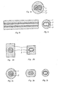
- Fig. 1a shows the section through a composite steel cylinder for plastics processing with a carrier sleeve 1 with an inserted two-part core 2 ', 3'.
- This workpiece was produced by eccentrically drilling a hole in a cylindrical metal bar, then a core 3 'was inserted into this bore, and subsequently a further bore overlapping the bore was made.
- the core 3 'and a further core 2' which were partially machined when the further bore was drilled, were cleaned (like with alcohol, trichlorethylene or the like) as well as the inner surface of the bore and reinserted in the bore. After closing the ends, e.g.
- the material of the two cores also forms a metal composite in spite of the high carbon or possibly present carbide content.
- a metal composite was produced between the cores, which led to a one-piece lining, which in turn is connected to the carrier sleeve 1 via a metal composite. Because of this structure, the stresses occurring in the hard carbon and / or carbide-rich lining material can be absorbed well by the tough alloy material of the carrier sleeve 1 and cracks and cracks in the lining 4 can be avoided.
- the deformation of the cores introduced into the carrier sleeve takes place at a corresponding temperature relatively uniformly and the cross-sectional shape of the cores is approximately or well maintained, so that originally, for example, circular cores circular bores can be introduced, which leave a lining 4 of substantially regular thickness. Due to the growing together of the core parts 2 ', 3' and the adaptation of the non-circular lining 4 to the non-circular shape of the lining 3, stresses due to the uneven thickness of the lining 4 are largely avoided or evenly transmitted to the carrier sleeve.
- Fig. 2a shows a section through a rectangular support sleeve 1, in which a round core 2 is introduced in the middle.
- the approximately square cross section of the carrier sleeve shown in FIG. 2b with an elongated or oval or elliptically shaped core is achieved by hot deformation of the carrier sleeve 1.
- two overlapping bores are made and the recess 3 is produced, as is e.g. is required to accommodate a twin screw for plastics processing.
- Fig. 3a shows a cylindrical carrier sleeve 1, in which a round core 2 is inserted essentially concentrically. For example, by pressing at elevated temperature, the carrier sleeve is deformed into a cylinder that is flattened on both sides. Overlapping recesses 3 are drilled into the oval or elongated core, as shown in FIG. 3b. The composite steel workpiece shown in Fig. 3b can then be turned to the workpiece shown in Fig. 3c.
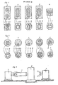
- the workpieces are usually deformed or reduced in cross-section by forging, pressing or rolling at elevated temperatures. If a composite steel workpiece is to be forged as shown in FIG. 1 a, it is clamped in a manipulator 5, as shown in FIG. 6.
- the manipulator 5 feeds the workpiece 1 to a long forging machine 6, from which it passes into another manipulator 7; the manipulators 5, 7 are used for guiding and further moving or rotating the workpiece during the long forging process.
- the invention provides that the workpiece alternate with its Ends A and B of the long forging machine 6 are fed, ie the workpiece is rotated by 180 ° after each stitch and fed to the forge again, which largely prevents undesirable twisting of the core.
- the individual stitches also run under the same conditions, in particular with the same feed or twist.
- the cross-sectional area or the degree of deformation can be varied in order to take into account the deformation or cross-sectional change that occurred in the previous stitch, in order to obtain actually identical deformations or cross-sectional changes in successive stitches.
- Forging presses with upper and lower dies or double or multiple hammer forges with conical hammers or presses with conical dies are advantageously used.
- a cross-sectional reduction by rolling is particularly suitable for the production of long composite steel workpieces.
- FIG. 4 shows different starting forms of carrier sleeves 1 provided with cores 2 in the upper row and in the lower row various composite steel workpieces obtained after the cross-sectional reduction, into which recesses 3 are made, which are delimited by the remnants of the cores 2 as lining 4.
- the composite steel workpiece according to FIG. 4a shows two inserted cores, which were deformed into a square in the course of the deformation of the carrier sleeve 1, into which two independent or two overlapping recesses 3 were made.
- the rectangular carrier sleeve according to Fig. 4b shows an essentially rectangular core 2.
- an essentially rectangular recess 3 e.g. by spark erosion, incorporated into the core material.
- the composite steel workpiece according to FIG. 4c shows a rectangular carrier sleeve 1, which uses an oval or elongated core has been; after drilling out three overlapping recesses 3, the workpiece shown was obtained.
- the shape of the core introduced into the carrier sleeve 1 and also the type of cross-sectional reduction influence the shape of the lining of the recess (es) in the finished composite steel workpiece.
- the circumference of the lining 4 is similar to the shape of the core 2, which was also shown in the composite steel workpiece according to FIGS. 4c and 4e, which changed from a rectangular or square shape to an octagonal Shape were reduced in cross section.
- 5 shows a view of composite steel workpieces which have been produced with carrier sleeves 1 having a circular cross section.
- 5a shows a carrier sleeve with a rectangular core, in which a rectangular recess 3 was formed after the metal composite had been deformed or produced.
- the composite workpiece according to FIG. 5b was formed from a carrier sleeve 1, into which a circular core was introduced asymmetrically. After the cross-sectional reduction at elevated temperature and the drilling process, an asymmetrically lying, essentially circular recess 3 was obtained, which was surrounded by a lining 4. Additional recesses 8, but without lining, were subsequently made in the carrier sleeve 1.
- the composite steel workpiece according to FIG. 5c was produced starting from an asymmetrically lying circular core; an asymmetrical reduction in cross-section of the carrier sleeve 1 resulted in an asymmetrical shape of the lining 4 in the core material recess 3.
- the composite steel workpiece according to FIG. 5e comprises a carrier sleeve 1 with an inserted triangular core 2, into which recesses 3 have been made after being deformed.
- the procedure is preferably such that first a bore is made, then a core is inserted into this bore, then the second Drilling is completed, and in this a core that complements the first partially machined core is inserted.
- the first core must prevent twisting, e.g. secured with a fitting bore formed at the interface between the core and the carrier sleeve and the fitting bolt inserted and secured against displacement, e.g. through a hole formed at the interface with a screwed-in screw. Welding to secure the cores is not possible if one or more hardenable steels are used.
- the cores Since drilling is carried out using drilling oil, the cores must be cleaned before the metal connection is formed, as must the inner surface of the carrier sleeve. In order to protect the cores from oxidation during the hot forming, the end faces of the composite steel workpieces are closed before the forming process.
- the hot forging or pressing or rolling for producing the metal composite takes place at temperatures between 1000 and 1260 ° C, in particular between 1170 and 1190 ° C.
- the possibility of varying the position of the core with respect to the center or the outer surface of the carrier sleeve is of particular importance if the finished composite steel workpiece is e.g. mechanical processing is to be subjected to e.g. to be able to attach cooling, heating or holding devices for its intended use.
- the possibility of fixing the core in any position in relation to the center point or the outer surface of the carrier sleeve and thus achieving directionally good strength properties of the composite steel cylinder was previously unknown or could not be produced due to the stresses occurring in the carrier sleeve and lining.
- non-uniform recesses in particular recesses 3 deviating from a circular shape, with a relatively thin lining 4, which eliminates the risk of warping in the event of temperature changes and the risk of breakage of linings that are too thick or of areas of the lining that are too thick, as they are e.g. occur when an elongated recess would be made in a circular core.
- the recesses 3 made in the composite steel workpieces can e.g. also have a cross-section which tapers conically in the longitudinal direction; this is achieved by e.g. introduces stepped holes, which are then tapered.
- the carrier sleeve 1 is made from a blacksmith temperable alloy of high strength and toughness, for example structural steel or case-hardening steel, and the lining 4 is made of a forgeable and heat-treatable, preferably wear and / or corrosion-resistant alloy, for example ledeburitic chromium steel, preferably with at least 11% Cr, in particular at least 14% Cr and at least 1%, preferably at least 1.8 or 2.3% C, and when the carrier sleeve 1 with the lining 4 is deformed to form the metal composite between these alloys by reducing the cross section.
- These steels each have the appropriate hardness and toughness in order to optimally support one another, in particular the formation of a metal bond between these alloys is also possible.
- alloys can also be deformed well at certain temperatures and the composite piece produced can then be hardened well. It goes without saying that modifications of these types of alloys formed by adding one or more alloying elements can also be used, with Mo, V, W and Co in particular as additional elements for the ledeburitic Cr steels up to a total of about 12% and for the stainless Cr steels Mo, Ni, V, W, Co, Ti, Nb in particular can be mentioned up to a total of about 6%.
Landscapes
- Engineering & Computer Science (AREA)
- Mechanical Engineering (AREA)
- Manufacturing & Machinery (AREA)
- Forging (AREA)
- Materials For Medical Uses (AREA)
- Pressure Welding/Diffusion-Bonding (AREA)
- Extrusion Moulding Of Plastics Or The Like (AREA)
- Injection Moulding Of Plastics Or The Like (AREA)
- Respiratory Apparatuses And Protective Means (AREA)
- Heat Treatment Of Steel (AREA)
- Manufacture Of Alloys Or Alloy Compounds (AREA)
- Percussion Or Vibration Massage (AREA)
- Treatment Of Steel In Its Molten State (AREA)
- Laminated Bodies (AREA)
Abstract
Description
- Die Erfindung betrifft ein Verbundstahlwerkstück bzw. einen Maschinenteil, umfassend eine mit zumindest einer in Längsrichtung verlaufenden Ausnehmung versehene, vorzugsweise zumindest über einen Teil ihrer Außenfläche zylindrisch geformte Trägerhülse, wobei die Ausnehmung(en) entlang ihres Umfanges mit zumindest einer verschleiß-und/oder korrosionsbeständigen Auskleidung unter Ausbildung eines z.B. durch Pressen, Schmieden, Walzen od. dgl. herstellten Metallverbundes bzw. einer metallischen Bindung mit der Trägerhülse versehen ist (sind). Ferner betrifft die Erfindung ein Verfahren zur Herstellung derartiger Verbundstahlwerkstücke.
- Ziel der Erfindung ist es, ein einfach durchzuführendes Verfahren zur Herstellung von Verbundstahlwerkstücken zu schaffen, welche innenseitig korrosions-und/oder verschleißfest sind und allen an sie während des Betriebes gestellten Anforderungen entsprechen. Insbesondere sollen die Verbundwerkstücke den in der Praxis an sie gestellten Form-bzw. Gestaltungsansprüchen gerecht werden und trotzdem die nötige Festigkeit besitzen. Derartige Verbundwerkstücke bzw. Maschineteile sind durch die in der Größenordnung von 1000 - 2000 bar sich ergebenden Innendrücke, die oftmals hohe Korrosionsbeanspruchung und nicht zuletzt durch die z.B. im Rahmen der Kunststoffverarbeitung gebräuchlichen Füllstoffe einem sehr hohen Verschleiß unterworfen. Es hat sich gezeigt, daß gewisse Füllstoffe, wie z.B. Glasfasern, die Standzeiten dieser Teile bis auf 1/10 des ursprünglichen Wertes absenken können. Zumal bei Spritzgußmaschinen etwa 0,25 mm als maximal zulässiges Spiel zwischen Schnecke und Zylinder gelten, kann man ermessen, welche Bedeutung der Verschleißfaktor besitzt und es wurden demgemäß seitens der Maschinenherstellter schon große Anstrengungen zur Lösung dieses technischen Problems unternommen.
- Dieses Ziel wird bei einem Verbundwerkstück der eingangs genannten Art dadurch erreicht, daß insbesondere zur Ausbildung eines Doppel- oder Mehrfachschneckenzylinders für die Kunststoffverarbeitung, die in der Trägerhülse ausgebildete Ausnehmung eine von einer Kreisform abweichende Querschnittsform, z.B. die Form von zumindest zwei sich überlappenden Kreisen, aufweist und daß die Metallverbundfläche zwischen der ebenfalls im Schnitt von Kreisform abweichenden Auskleidung und der Trägerhülse längs ihres Umfanges unterschiedliche Normalabstände von der Umfangsfläche der Trägerhülse besitzt. Alternativ kann vorgesehen sein, daß insbesondere zur Ausbildung eines Doppel- oder Mehrfachschneckenzylinders für die Kunststoffverarbeitung, die in der Trägerhülse ausgebildete kreisförmige Ausnehmung in Bezug auf die Mitte der Trägerhülse exzentrisch angeordnet ist und daß die Metallverbundfläche zwischen der ebenfalls im Schnitt Kreisform aufweisenden Auskleidung und der Trägerhülse längs ihres Umfanges unterschiedliche Normalabstände von der Umfangsfläche der Trägerhülse besitzt.
- Ein Verfahren der eingangs genannten Art ist erfindungsgemäß dadurch gekennzeichnet, daß insbesonder zur Ausbildung eines Doppel-oder Mehrfachschneckenzylinders aus Verbundstahl für die Kunststoffverarbeitung, die an der(n) Stelle(n) der gewünschten Ausnehmung(en) mit zumindest einem Kern versehene Trägerhülse gemeinsam mit dem(n) Kern(en) einer Verformung bei höherer Temperatur, insbesondere Querschnittsverringerung , unterworfen , dem (n) Kern(en) eine von Kreisform abweichende Querschnittsform erteilt und in dem(n) Kern(en) die Ausnehmung(en) ausgebildet wird (werden). Alternativ kann vorgesehen sein, daß, insbesondere zur Ausbildung eines Doppel-oder Mehrfachschneckenzylinders aus Verbundstahl für die Kunststoffverarbeitung, die an der(n) Stelle(n) der gewünschten Ausnehmung(en) mit zumindest einem Kern versehene Trägerhülse gemeinsam mit dem(n) Kern(en) einer Warmverformung , insbesondere Querschnittsverringerung, unterworfen wird, aus welcher ein kreisförmiger Kern mit einer bezüglich des Mittelpunktes der Trägerhülse exzentrischen bzw. bezüglich der Umfangsfläche der Trägerhülse unterschiedliche Abstände besitzenden Lage hervorgeht und daß in dem Kern die Ausnehmung(en) ausgebildet wird ( werden ).
- Mit den erfindungsgemäßen Verbundstahlwerkstücken kann im wesentlichen allen in der Praxis an sie gestellten Form- und Festigkeitswünschen entsprochen werden.
- Bevorzugte Ausführungsformen der Erfindung sind der folgenden Beschreibung , den Zeichnungen und den Unteransprüchen zu entnehmen.
- Im folgenden wird die Erfindung anhand der Zeichnung beispielsweise näher erläutert. Es zeigen
- Fig. 1a, 1b, 1c sowie Fig. 2a und 2b sowie Fig. 3a und 3c verschiedene Stufen des Herstellungsverfahrens bzw. verschiedene Verbundstahlwerkstücke im Schnitt;
- Fig. 4 und 5 zeigen verschiedene Ausgangswerkstücke und Endprodukte im Schnitt und
- Fig. 6 zeigt schematisch eine Anlage zur Durchführung des erfindungsgemäßen Verfahrens.
- Das erfindungsgemäße Verfahren geht von der Herstellung einer Trägerhülse aus, die mit einem Kern versehen wird, worauf die mit dem Kern versehene Trägerhülse einer Querschnittsverminderung bei erhöhter Temperatur unterworfen wird, um einen Metallverbund zwischen dem Kern und der Trägerhülse zu erreichen. Dazu wird in einen Metallbarren bzw. ein Metallprofil als Trägerhülse ein Loch (oder mehrere Löcher) gebohrt bzw. eingearbeitet, in welche(s) eine bzw. mehrere Metallstange(n) als Kern(e) genau passend eingesetzt werden, nachdem die Innenflächen der Trägerhülse und die Außenoberfläche des(r) Kerne(s) gereinigt wurden. Nach Anlegen eines Vakuums werden die Enden der Trägerhülse luftdicht verschlossen, um eine Oxidation bei der darauffolgenden Warmbearbeitung zu vermeiden und bei der entsprechenden Bearbeitungstemperatur, vorzugsweise etwa 1000 bis 1260° C, den Metallverbund herzustellen.
- Fig. 1a zeigt den Schnitt durch einen Verbundstahlzylinder für die Kunststoffverarbeitung mit einer Trägerhülse 1 mit einem eingesetzten zweiteiligen Kern 2′, 3′. Dieses Werkstück wurde hergestellt, indem in einem zylindrischen Metallbarren exzentrisch ein Loch gebohrt wurde, daraufhin in diese Bohrung ein Kern 3′ eingesetzt wurde, und im folgenden eine die angebrachte Bohrung überlappende weitere Bohrung angebracht wurde. Der bei der Anbringung der weiteren Bohrung teilweise abgearbeitete Kern 3′ und ein weiterer Kern 2′ wurden ebenso wie die Innenfläche der Bohrungen gereinigt ( z.B. mit Alkohol, Trichloräthylen od. dgl.) und in die Bohrungen wieder eingesetzt. Nach Verschluß der Enden, z.B. durch Aufschweißen einer Platte und Evakuieren wurde dieses Werkstück einer Warmverformung bzw. Querschnittsverringerung bei 1180 C, d.h. einem Warmschmieden, unterworfen. Es ergab sich das in Fig. 1b vergrößert dargestellte Verbundstahlwerkstück, bei dem die Kerne 2′, 3′ und die Trägerhülse 1 über einem Metallverbund zusammengehalten sind. Durch Anbringen von zwei weiteren sich überlappenden Bohrungen in den Kernen 2′, 3′ ergab sich eine Ausnehmung 3, die von einer Auskleidung 4 aus Kernmaterial umgeben ist.
- Überraschenderweise zeigte sich, daß auch das Material der beiden Kerne trotz des hohen Kohlenstoff- bzw. gegebenenfalls vorliegenden Carbidgehaltes einen Metallverbund eingeht. Die von zwei einander überlappenden Kreisen gebildete Ausnehmung 3, die von der Auskleidung 4 umgeben ist, die im Metallverbund mit der Trägerhülse 1 steht, wird vom Material der beiden Kerne umschlossen; zwischen den Kernen wurde ein Metallverbund hergestellt, der zu einer einstückigen Auskleidung führte, welche ihrerseits über einen Metallverbund mit der Trägerhülse 1 verbunden ist. Aufgrund dieses Aufbaues können die in dem harten kohlenstoff-und/oder carbidreichen Aufkleidungsstoff auftretenden Spannungen gut von dem zähen Legierungsmaterial der Trägerhülse 1 aufgenommen werden und Risse und Sprünge in der Auskleidung 4 vermieden werden. Da die Querschnittsverminderungen bei den Schmiede-,Press-oder Walzvorgängen gut beherrschbar sind, erfolgt die bei entsprechender Temperatur vorgenommene Verformung der in die Trägerhülse eingebrachten Kerne relativ gleichmäßig und es wird die Querschnittsform der Kerne annähernd bzw. gut beibehalten, sodaß in ursprünglich z.B. kreisförmigen Kernen kreisförmige Bohrungen eingebracht werden können, welche eine Auskleidung 4 von im wesentlichen regelmäßiger Dicke stehen lassen. Aufgrund des Zusammenwachsens der Kernteile 2′, 3′ und der Anpassung der unrunden Auskleidung 4 an die unrunde Form der Auskleidung 3 werden Spannungen aufgrund ungleicher Dicke der Auskleidung 4 weitgehend vermieden bzw. gleichmäßig auf die Trägerhülse übertragen.
- Fig. 2a zeigt einen Schnitt durch eine rechteckförmige Trägerhülse 1, in die mittig ein runder Kern 2 eingebracht ist. Durch eine Warmverformung der Trägerhülse 1 wird der in Fig. 2b gezeigte etwa quadratische Querschnitt der Trägerhülse mit einem langgestreckten bzw. oval bzw. elliptisch geformten Kern erreicht. Im folgenden werden zwei überlappende Bohrungen vorgenommen und die Ausnehmung 3 hergestellt, wie sie z.B. für die Aufnahme einer Doppelschnecke für die Kunststoffverarbeitung benötigt wird.
- Bevorzugterweise kann derart vorgegangen werden, daß man unter Zuhilfenahme der Formeln

K = Kern φ
x = Achsabstand
D = vergrößerter Bohr φ
V = Verschmiedungsgrad
H = Rohrmaßhöhe
B = Rohrmaßbreite
S = Seitenlänge des 4-kant nach Schmieden
bedeuten. - Fig. 3a zeigt eine zylindrische Trägerhülse 1, in die ein runder Kern 2 im wesentlichen konzentrisch eingesetzt ist. Es erfolgt z.B. durch Pressen bei erhöhter Temperatur, eine Verformung der Trägerhülse zu einem beidseitig abgeplatteten Zylinder. In dem ovalen bzw langgestreckten Kern werden überlappende Ausnehmungen 3 eingebohrt, wie es in Fig. 3b dargestellt ist. Das in Fig. 3b dargestellte Verbundstahlwerkstück kann sodann zu dem in Fig. 3c dargestellten Werkstück abgedreht werden.
- Es hat sich gezeigt, daß mit der erfindungsgemäßen Vorgangsweise in einfacher Weise unrunde bzw. außermittig liegende Ausnehmungen leicht und genau hergestellt werden können.
- Üblicherweise erfolgt die Verformung bzw. Querschnittsverminderung der Werkstücke durch Schmieden, Pressen oder Walzen bei erhöhten Temperaturen. Wenn ein Verbundstahlwerkstück wie in der Fig. 1a dargestellt, geschmiedet werden soll, so wird dieses in einen Manipulator 5 eingespannt, wie in Fig. 6 dargestellt ist. Der Manipulator 5 führt das Werkstück 1 einer Langschmiedemaschine 6 zu, aus der es in einen weiteren Manipulator 7 gelangt; die Manipulatoren 5, 7 dienen zur Führung und Weiterbewegung bzw. Verdrehung des Werkstückes während des Langschmiedevorganges. Um nunmehr eine beim Schmieden mit Manipulatoren in Langschmieden hervorgerufene Verwindung des Werkstückes bzw. seines unrunden Kernen zu vermeiden, welcher Kern danach nicht ausbohrbar wäre, ist erfindungsgemäß vorgesehen, daß das Werkstück abwechsend mit seinen Enden A und B der Langschmiedemaschine 6 zugeführt wird, d.h. das Werkstück wird nach jedem Stich um 180° gedreht und erneut der Schmiede zugeführt, womit unerwünschte Verwindungen des Kerns weitgehend vermieden werden. Die einzelnen Stiche laufen ferner unter gleichen Bedingungen, insbesondere mit gleichem Vorschub bzw. gleicher Verdrehung ab. Allerdings kann eine Variation der Querschnittsverminderung bzw. des Verformungsgrades vorgenommen werden, um die im vorangehenden Stich eingetretene Verformung bzw. Querschnittsänderung zu berücksichtigen, um in aufeinanderfolgenden Stichen tatsächliche gleiche Verformungen bzw. Querschnittsänderungen zu erhalten.
- Vorteilhafterweise werden Schmiedepressen mit Ober-und Untergesenk oder Zwei-oder Mehrhämmerschmieden mit konischen Hämmern bzw. Pressen mit konischen Gesenken eingesetzt. Für eine Herstellung von langen Verbundstahlwerkstücken eignet sich insbesondere eine Querschnittsverringerung durch Walzen.
- Fig. 4 zeigt verschiedene Ausgangsformen von mit Kernen 2 versehenen Trägerhülsen 1 in der oberen Reihe und in der unteren Reihe verschiedene nach der Querschnittsverminderung erhaltene Verbundstahlwerkstücke, in die Ausnehmungen 3 eingebracht sind, die von den Resten der Kerne 2 als Auskleidung 4 begrenzt sind. Das Verbundstahlwerkstück gemäß Fig. 4a zeigt zwei eingebrachte Kerne, die im Zuge der Verformung der Trägerhülse 1 zu einem Quadrat zu Ellipsen verformt wurden, in die zwei unabhängige bzw. zwei sich überlappende Ausnehmungen 3 eingebracht wurden.
- Die rechteckige Trägerhülse gemäß Fig. 4b zeigt einen im wesentlichen rechteckigen Kern 2. Nach der Querschnittsreduktion wurde eine im wesentlichen rechteckige Ausnehmung 3, z.B. durch Funkenerosion, in das Kernmaterial eingearbeitet.
- Das Verbundstahlwerkstück gemäß Fig. 4c zeigt eine rechteckige Trägerhülse 1, der ein ovaler bzw. langgestreckter Kern eingesetzt wurde; nach Ausbohren von drei sich überlappenden Ausnehmungen 3 ergab sich das dargestellte Werkstück.
- Insbesondere aus Fig. 4d und 4e ist zu erkennen, daß die Form des in die Trägerhülse 1 eingebrachten Kernes und auch die Art der Querschnittsreduktion die Form der Auskleidung der Ausnehmung(en) im fertiggestellten Verbundstahlwerkstück beeinflussen. Man erkennt, daß bei dem in Fig. 4d dargestellten Verbundstahlwerkstück der Umfang der Auskleidung 4 der Form des Kernes 2 ähnlich ist, was sich auch bei dem Verbundstahlwerkstück gemäß Fig. 4c und 4e zeigte, die von einer rechteckigen bzw. quadratischen Form auf eine achteckige Form querschnittsverringert wurden.
- Beim Schmieden der Trägerhülsen ist es bevorzugt, wenn ein Paar von ebenen Schmiedebacken und ein Paar von bombierten Schmiedebacken vorgesehen sind, wobei die bombierten Schmiedebacken insbesondere auf die zur Längserstreckung des bzw. der Kerne(s) parallelen Seiten einwirken.
- Fig. 5 zeigt eine Ansicht von Verbundstahlwerkstücken, welche mit kreisförmigen Querschnitt aufweisenden Trägerhülsen 1 hergestellt wurden. Fig. 5a zeigt eine Trägerhülse mit einem rechteckigen Kern, in dem nach Verformung bzw. Herstellung des Metallverbundes eine rechteckige Ausnehmung 3 ausgebildet wurde. Das Verbundwerkstück gemäß Fig. 5b wurde aus einer Trägerhülse 1 ausgebildet, in die asymmetrisch ein kreisförmiger Kern eingebracht wurde. Nach der Querschnittsverringerung bei erhöhter Temperatur und dem Bohrvorgang ergab sich eine asymmetrisch liegende, im wesentlichen kreisförmige Ausnehmung 3, die von einer Auskleidung 4 umgeben war. Zusätzliche Ausnehmungen 8, allerdings ohne Auskleidung, wurden nachträglich in die Trägerhülse 1 eingebracht. Das Verbundstahlwerkstück gemäß Fig. 5c wurde ausgehend von einem asymmetrisch liegenden kreisförmigen Kern hergestellt; eine asymmtrische Querschnittsverrringerung der Trägerhülse 1 ergab eine asymmtrische Form der Auskleidung 4 der im Kernmaterial hergestellten Ausnehmung 3.
- Wie das Verbundstahlwerkstück gemäß Fig. 5d zeigt, ist es auch möglich, bei kreisförmigen Trägerhülsen 1 mehrere Kerne 2 einzusetzen, die selbst wiederum von mehreren Bauteilen gebildet sind, und diese nach Verformung mit einander überlappenden oder voneinander getrennten Ausnehmungen 3 zu versehen. Das Verbundstahlwerkstück gemäß Fig. 5e umfaßt eine Trägerhülse 1 mit einem eingesetzten dreieckförmigen Kern 2, in den nach Verformen Ausnehmungen 3 eingebracht wurden.
- Werden in eine Trägerhülse zum Einbringen der Kerne oder in die verformten Kerne zum Einbringen der Ausnehmungen 3 zwei oder mehr überlappende Bohrungen eingebracht, so wird bevorzugterweise derart vorgegangen, daß zuerst eine Bohrung gefertigt wird, daraufhin in diese Bohrung ein Kern eingesetzt wird, daraufhin die zweite Bohrung fertiggestellt wird, und in diese ein den ersten teilweise abgearbeiteten Kern ergänzender Kern eingesetzt wird. Der erste Kern muß dabei gegen Verdrehung, z.B. mit einer an der Grenzfläche zwischen Kern und Trägerhülse ausgebildeten Paßbohrung und eingesetztem Paßbolzen und gegen Verschiebung gesichert werden, z.B. durch eine an der Grenzfläche ausgebildete Bohrung mit einer eingedrehten Schraube. Ein Schweißen ist zur Sicherung der Kerne nicht möglich, wenn ein oder mehrere härtbare Stähle verwendet werden. Da unter Verwendung von Bohröl gebohrt wird, müssen die Kerne vor Ausbildung der Metallverbindung gereinigt werden,ebenso wie die Innenfläche der Trägerhülse. Um die Kerne während der Warmverformung vor einer Oxidation zu schützen, werden die Endflächen der Verbundstahlwerkstücke vor dem Verformungsvorgang verschlossen.
- Das Warmschmieden bzw. Pressen bzw. Walzen zur Herstellung des Metallverbundes erfolgt bei Temperaturen zwischen 1000 und 1260°C, insbesondere zwischen 1170 und 1190°C.
- Die Möglichkeit der Variation der Lage des Kernes in Bezug auf den Mittelpunkt oder die Außenfläche der Trägerhülse ist insbesondere von Wichtigkeit, wenn das fertiggestellte Verbundstahlwerkstück einer z.B. mechanischen Abarbeitung unterworfen werden soll, um z.B. für seine gedachte Verwendung am Umfang Kühl-,Heiz- oder Halteeinrichtungen anbringen zu können. Die Möglichkeit, den Kern in Bezug auf den Mittelpunkt bzw. die Außenfläche der Trägerhülse in beliebige Position festzulegen und damit richtungsorientiert gute Festigkeitseigenschaften des Verbundstahlzylinders zu erreichen, war bislang nicht bekannt bzw. aufgrund der auftretenden Spannungen in der Trägerhülse und Auskleidung nicht herstellbar. Es wird erfindungsgemäß möglich, ungleichförmige Ausnehmungen, insbesondere von Kreisform abweichende Ausnehmungen 3, mit einer relativ dünnen Auskleidung 4 herzustellen, womit die Verzugsgefahr bei Temperaturänderungen und die Bruchgefahr von zu dicken Auskleidungen bzw. von zu dicken Stellen der Auskleidungen im Betrieb beseitigt werden, wie sie z.B. auftreten, wenn in einen kreisförmigen Kern eine langgestreckte Ausnehmung eingebracht würde.
- Sofern es sich nicht um kreisförmige Kerne handelt, welche in Bohrungen der Trägerhülse eingesetzt werden können, könnten in der Trägerhülse, z.B. durch Formschneiden, entsprechende quadratische, rechteckige oder anders geformte Ausnehmungen ausgebildet werden, in die passende, z.B. durch Strangpressen od. dgl. hergestellte, ebenfalls quadratische, rechteckige oder anders geformte Kerne eingesetzt werden können.
- Die in die Verbundstahlwerkstücke eingebrachten Ausnehmungen 3 können z.B. auch einen sich in Längsrichtung konisch verjüngenden Querschnitt aufweisen; dies wird erreicht, indem man z.B. abgestufte Bohrungen einbringt, die sodann konisch ausgedreht werden.
- Vorteilhaft ist es, wenn die Trägerhülse 1 aus einer schmied-und vergütbaren Legierung hoher Festigkeit und Zähigkeit, z.B. Baustahl oder Einsatzstahl, besteht und die Auskleidung 4 von einer schmiedbaren und vergütbaren, vorzugsweise verschleiß-und/oder korrosionsbeständigen, Legierung, z.B. ledeburitischem Chromstahl, vorzugsweise mit zumindest 11 % Cr, insbesondere zumindest 14 % Cr und zumindest 1 %, vorzugsweise zumindest 1,8 bzw. 2,3 % C, gebildet ist, und wenn die Trägerhülse 1 mit der Auskleidung 4 zur Ausbildung des Metallverbundes zwischen diesen Legierungen durch Querschnittsreduktion verformt ist. Diese Stähle besitzen jeweils entsprechende Härte und Zähigkeit, um einander optimal zu unterstützen, insbesondere ist auch die Ausbildung eines Metallverbundes zwischen diesen Legierungen gut möglich. Ebenfalls lassen sich diese Legierungen bei gewissen Temperaturen miteinander gut verformen und das hergestellte Verbundstück kann anschließend gut gehärtet werden. Es versteht sich, daß auch durch Zusatz eines oder mehrerer Legierungselemente gebildete Modifikationen dieser genannten Legierungstypen einsetzbar sind, wobei als Zusatzelemente für die ledeburitischen Cr-Stähle insbesondere Mo, V, W und Co bis insgesamt etwa 12 % und für die nicht rostenden Cr-Stähle insbesondere Mo, Ni, V, W, Co, Ti, Nb bis insgesamt etwa 6 % zu nennen sind.
Claims (22)
Applications Claiming Priority (2)
| Application Number | Priority Date | Filing Date | Title |
|---|---|---|---|
| AT0159588A AT393980B (de) | 1988-06-20 | 1988-06-20 | Verfahren zur herstellung von verbundstahlwerkstuecken und verbundstahlwerkstueck |
| AT1595/88 | 1988-06-20 |
Publications (3)
| Publication Number | Publication Date |
|---|---|
| EP0348381A2 true EP0348381A2 (de) | 1989-12-27 |
| EP0348381A3 EP0348381A3 (de) | 1991-01-16 |
| EP0348381B1 EP0348381B1 (de) | 1993-11-03 |
Family
ID=3516821
Family Applications (1)
| Application Number | Title | Priority Date | Filing Date |
|---|---|---|---|
| EP89890164A Expired - Lifetime EP0348381B1 (de) | 1988-06-20 | 1989-06-15 | Verbundstahlwerkstück und Verfahren zu seiner Herstellung |
Country Status (11)
| Country | Link |
|---|---|
| US (1) | US5093209A (de) |
| EP (1) | EP0348381B1 (de) |
| JP (1) | JPH0245119A (de) |
| KR (1) | KR920007833B1 (de) |
| CN (1) | CN1040339A (de) |
| AT (2) | AT393980B (de) |
| AU (1) | AU612268B2 (de) |
| DE (1) | DE58906078D1 (de) |
| FI (1) | FI893006A7 (de) |
| NO (1) | NO892508L (de) |
| ZA (1) | ZA894668B (de) |
Cited By (6)
| Publication number | Priority date | Publication date | Assignee | Title |
|---|---|---|---|---|
| EP0453345A1 (de) * | 1990-04-05 | 1991-10-23 | Xaloy, Inc. | Gegen Korrosion bei hoher Temperatur widerstandsfähiger bimetallischer Zylinder |
| EP0652101A1 (de) * | 1993-11-04 | 1995-05-10 | Xaloy, Inc. | Hohlzylindern für Spritzgiessen oder für Strangpressen von Thermoplasten und Legierungszusammensetzungen für diese Gegenstände |
| WO1998022274A1 (fr) * | 1996-11-21 | 1998-05-28 | Clextral | Fourreau de machine d'extrusion |
| WO2003026814A1 (de) * | 2001-09-22 | 2003-04-03 | Robert Bosch Gmbh | Verfahren zum herstellen einer welle mit hülse sowie vorrichtung beinhaltend eine solche welle |
| FR2911284A1 (fr) * | 2007-01-15 | 2008-07-18 | Boule Obut Soc Par Actions Sim | Boule de jeu bi matiere, par exemple boule de petanque, et procede de realisation |
| WO2012143668A1 (en) * | 2011-04-18 | 2012-10-26 | Cladinox International Limited | Methods for the production of clad steel products |
Families Citing this family (19)
| Publication number | Priority date | Publication date | Assignee | Title |
|---|---|---|---|---|
| USD465585S1 (en) | 1993-03-26 | 2002-11-12 | Frank Venegas, Jr. | Stanchion cover |
| USD374941S (en) | 1994-03-07 | 1996-10-22 | Venegas Jr Frank | Combined stanchion with sleeve and signage |
| US6218026B1 (en) | 1995-06-07 | 2001-04-17 | Allison Engine Company | Lightweight high stiffness member and manufacturing method thereof |
| DE19530026A1 (de) * | 1995-08-16 | 1997-02-20 | Werner & Pfleiderer | Schneckensatzelement für Schneckenmaschinen |
| US6779287B2 (en) | 2000-05-12 | 2004-08-24 | Frank Venegas, Jr. | Integral post sleeve and sign |
| US20040060257A1 (en) * | 2000-06-19 | 2004-04-01 | Frank Venegas | Stanchion covers |
| US6887322B2 (en) | 2001-04-09 | 2005-05-03 | Wexco Corporation | High pressure cylinders including backing steel with tool steel lining |
| US6594936B1 (en) * | 2002-10-03 | 2003-07-22 | Gary Sniezak | Method for lining a gun barrel |
| AT413269B (de) * | 2004-07-08 | 2006-01-15 | Theysohn Extrusionstechnik Ges | Gehäuse für einen doppelschneckenextruder sowie herstellungsverfahren |
| WO2011048364A1 (en) | 2009-10-22 | 2011-04-28 | Whitehead, John, Anthony, Bailie | Corrosion resistant metal products |
| CN103144265B (zh) * | 2013-03-07 | 2017-05-31 | 上海逊达橡塑机械制造有限公司 | 一种挤出机的双金属筒体 |
| CN103143897B (zh) * | 2013-03-20 | 2016-01-20 | 沈阳飞机工业(集团)有限公司 | 细长窄条长桁防变形加工方法 |
| CN103950181A (zh) * | 2014-04-03 | 2014-07-30 | 于德胜 | 镶嵌高耐磨基材的锥双机筒 |
| CN104607889B (zh) * | 2015-01-13 | 2017-01-04 | 哈尔滨飞机工业集团有限责任公司 | 一种双曲面成型模工装的制造方法 |
| CN108637598A (zh) * | 2018-04-28 | 2018-10-12 | 王彩霞 | 哑铃、杠铃手柄抗氧化金属表面的制造方法 |
| CN108819162A (zh) * | 2018-05-18 | 2018-11-16 | 河北工业职业技术学院 | 一种双螺杆挤出机筒体内壁耐磨涂层的制备方法 |
| CN108526830A (zh) * | 2018-07-24 | 2018-09-14 | 东北大学 | 一种轴类件的复合制备工艺 |
| CN111015125A (zh) * | 2019-12-30 | 2020-04-17 | 成都康思达科技有限公司 | 铜球套装配工艺 |
| CN115199686B (zh) * | 2022-07-15 | 2023-10-20 | 杭州萧山红旗摩擦材料有限公司 | 工程车桥式高碳制动器摩擦片及加工工艺 |
Family Cites Families (22)
| Publication number | Priority date | Publication date | Assignee | Title |
|---|---|---|---|---|
| FR871829A (fr) * | 1941-04-30 | 1942-05-18 | Procédé pour doubler des tuyaux | |
| US3945555A (en) * | 1972-05-24 | 1976-03-23 | The United States Of America As Represented By The Secretary Of The Navy | Production of beryllium reinforced composite solid and hollow shafting |
| US3913208A (en) * | 1973-01-02 | 1975-10-21 | Cnen | Process for producing bimetallic and polymetallic bodies in which the metallic components are joined together with metallurgical bond |
| GB1469237A (en) * | 1973-05-30 | 1977-04-06 | Benndahl L | Conveyor system including an overhead rail and a number of self propelled driving units |
| DE2358362A1 (de) * | 1973-11-23 | 1975-05-28 | Heinz Dipl Ing Weber | Doppelschneckenzylinder |
| GB1527491A (en) * | 1974-09-23 | 1978-10-04 | Cosan Crisplant As | Conveyor systems |
| JPS5319958A (en) * | 1976-07-09 | 1978-02-23 | Asahi Chemical Ind | Long stze clad steel pipe manufacturing |
| CH602330A5 (de) * | 1976-08-26 | 1978-07-31 | Bbc Brown Boveri & Cie | |
| DE2752002C3 (de) * | 1977-11-22 | 1980-09-11 | Fa. Friedrich Theysohn, 3012 Langenhagen | Verfahren zur Erzeugung einer verschleißfesten Schicht auf der inneren Oberfläche des Gehäuses eines Doppelschneckenextruders |
| DE2756422C2 (de) * | 1977-12-17 | 1984-12-13 | Walter Attnang-Puchheim Sticht | Fertigungsanlage für in mehreren Schritten herzustellende Bauteile |
| DE2801499C3 (de) * | 1978-01-11 | 1981-05-27 | Siemens AG, 1000 Berlin und 8000 München | Extruder zur Behandlung hochtemperaturempfindlicher Kunststoffe |
| AT379340B (de) * | 1979-10-31 | 1985-12-27 | Sticht Walter | Einrichtung zur herstellung bzw. handhabung von werkstuecken |
| NL8003332A (nl) * | 1980-06-06 | 1981-07-01 | Wavin Bv | Extruder-binnenbekleding. |
| AT368923B (de) * | 1980-11-06 | 1982-11-25 | Ver Edelstahlwerke Ag | Verfahren zur herstellung von maschinenhohlzylindern |
| JPS60181208A (ja) * | 1984-02-28 | 1985-09-14 | Hitachi Metals Ltd | プラスチツク成形機用多軸シリンダの製造法 |
| DD225953A1 (de) * | 1984-06-15 | 1985-08-14 | Karl Marx Stadt Maschf | Verschleissbestaendiger extruderzylinder, insbesondere fuer doppelschneckenextruder |
| JPS61154756A (ja) * | 1984-12-27 | 1986-07-14 | Hitachi Metals Ltd | プラスチツク成形機用多孔シリンダの製造方法 |
| JPS61216846A (ja) * | 1985-03-20 | 1986-09-26 | Hitachi Metals Ltd | プラスチツク成形機用多孔シリンダの製造方法 |
| EP0233437B1 (de) * | 1986-02-21 | 1990-02-07 | MANNESMANN Aktiengesellschaft | Aus zwei Schichten bestehendes korrosionsbeständiges Rohr oder dergleichen Behälter |
| JPS63265617A (ja) * | 1986-12-19 | 1988-11-02 | Hitachi Metals Ltd | 耐摩耗耐食性複合シリンダ |
| JPS63221025A (ja) * | 1987-03-10 | 1988-09-14 | Hitachi Metals Ltd | 耐摩耗耐食性複合シリンダ |
| EP0399071B1 (de) * | 1989-05-23 | 1995-08-02 | Kubota Corporation | Verbundmetallröhre mit vortrefflicher Beständigkeit gegen Korrosion, hohe Temperaturen und Drücke |
-
1988
- 1988-06-20 AT AT0159588A patent/AT393980B/de not_active IP Right Cessation
-
1989
- 1989-04-03 ZA ZA894668A patent/ZA894668B/xx unknown
- 1989-06-08 JP JP1144322A patent/JPH0245119A/ja active Pending
- 1989-06-15 AT AT89890164T patent/ATE96724T1/de not_active IP Right Cessation
- 1989-06-15 DE DE89890164T patent/DE58906078D1/de not_active Expired - Fee Related
- 1989-06-15 EP EP89890164A patent/EP0348381B1/de not_active Expired - Lifetime
- 1989-06-16 NO NO89892508A patent/NO892508L/no unknown
- 1989-06-19 FI FI893006A patent/FI893006A7/fi not_active Application Discontinuation
- 1989-06-20 US US07/368,559 patent/US5093209A/en not_active Expired - Fee Related
- 1989-06-20 AU AU36663/89A patent/AU612268B2/en not_active Ceased
- 1989-06-20 CN CN89104097A patent/CN1040339A/zh active Pending
- 1989-06-20 KR KR1019890008474A patent/KR920007833B1/ko not_active Expired
Cited By (8)
| Publication number | Priority date | Publication date | Assignee | Title |
|---|---|---|---|---|
| EP0453345A1 (de) * | 1990-04-05 | 1991-10-23 | Xaloy, Inc. | Gegen Korrosion bei hoher Temperatur widerstandsfähiger bimetallischer Zylinder |
| EP0652101A1 (de) * | 1993-11-04 | 1995-05-10 | Xaloy, Inc. | Hohlzylindern für Spritzgiessen oder für Strangpressen von Thermoplasten und Legierungszusammensetzungen für diese Gegenstände |
| US5565277A (en) * | 1993-11-04 | 1996-10-15 | Xaloy, Inc. | Injection molding and extrusion barrels and alloy compositions thereof |
| WO1998022274A1 (fr) * | 1996-11-21 | 1998-05-28 | Clextral | Fourreau de machine d'extrusion |
| WO2003026814A1 (de) * | 2001-09-22 | 2003-04-03 | Robert Bosch Gmbh | Verfahren zum herstellen einer welle mit hülse sowie vorrichtung beinhaltend eine solche welle |
| FR2911284A1 (fr) * | 2007-01-15 | 2008-07-18 | Boule Obut Soc Par Actions Sim | Boule de jeu bi matiere, par exemple boule de petanque, et procede de realisation |
| WO2012143668A1 (en) * | 2011-04-18 | 2012-10-26 | Cladinox International Limited | Methods for the production of clad steel products |
| US9346093B2 (en) | 2011-04-18 | 2016-05-24 | Cladinox International Limited | Methods for the production of clad steel products |
Also Published As
| Publication number | Publication date |
|---|---|
| NO892508D0 (no) | 1989-06-16 |
| CN1040339A (zh) | 1990-03-14 |
| KR900000137A (ko) | 1990-01-30 |
| ATE96724T1 (de) | 1993-11-15 |
| JPH0245119A (ja) | 1990-02-15 |
| ZA894668B (en) | 1990-06-27 |
| EP0348381B1 (de) | 1993-11-03 |
| NO892508L (no) | 1989-12-21 |
| US5093209A (en) | 1992-03-03 |
| DE58906078D1 (de) | 1993-12-09 |
| FI893006A0 (fi) | 1989-06-19 |
| FI893006A7 (fi) | 1989-12-21 |
| AU3666389A (en) | 1990-04-12 |
| AT393980B (de) | 1992-01-10 |
| EP0348381A3 (de) | 1991-01-16 |
| ATA159588A (de) | 1991-07-15 |
| AU612268B2 (en) | 1991-07-04 |
| KR920007833B1 (ko) | 1992-09-18 |
Similar Documents
| Publication | Publication Date | Title |
|---|---|---|
| EP0348381B1 (de) | Verbundstahlwerkstück und Verfahren zu seiner Herstellung | |
| DE3009656C2 (de) | Verfahren zum Herstellen einer Nockenwelle | |
| AT402539B (de) | Kraftstoff-einspritzleitung für brennkraftmaschinen sowie verfahren zum herstellen derselben | |
| DE69710116T2 (de) | Verfahren zur Herstellung eines Rollings für eine geschmiedete Pleuelstange | |
| DE3106457C2 (de) | Verfahren zum Herstellen einer Nockenwelle oder dergleichen, und Vorrichtung zur Durchführung eines solchen Verfahrens | |
| DE69225466T2 (de) | Kaliberwalze | |
| DE19815670A1 (de) | Selbstgewindeformende Schraube aus korrosionsbeständigem Material | |
| EP0074347B1 (de) | Verfahren zur Herstellung von Förderschnecken | |
| DE2143784A1 (de) | Verbindungsbolzen, insbesondere schraubenbolzen und verfahren zur herstellung desselben | |
| DE4401674A1 (de) | Verfahren sowie Vorrichtung zum Lochen von Werkstücken | |
| EP1027177B1 (de) | Verfahren zum herstellen von nickel-titan-hohlprofilen | |
| EP1201775B1 (de) | Verfahren zur Herstellung zylindrischer Hohlkörper und Verwendung derselben | |
| DE102019002187B4 (de) | Verfahren und Vorrichtung zum Herstellen eines Bauteils mit Gewinde | |
| DE60313748T2 (de) | Verfahren zur herstellung eines torsionsstabs für eine fahrzeuglenkvorrichtung | |
| EP4417336B1 (de) | Verfahren zum härten und richten hochlegierter werkzeugstähle | |
| WO2008107045A1 (de) | Bearbeitung von werkstücken zur verbesserung der materialeigenschaften | |
| EP4526576B1 (de) | Kettenglied und ein verfahren zur herstellung eines kettengliedes | |
| DE60116885T2 (de) | Verfahren zur herstellung eines geschlossenen profils | |
| EP1366895B1 (de) | Composite-Flachstab | |
| EP0593408A1 (de) | Verbundwalze | |
| EP0299948A2 (de) | Verfahren und Schmiedemaschine zur Herstellung von Verbundkörpern | |
| DE3035289C2 (de) | ||
| DE2262140A1 (de) | Verfahren zum richten von stahlhalbzeug | |
| AT520593B1 (de) | Zug- oder Druckstange oder Verriegelungsmutter für eine Formgebungsmaschine | |
| EP0430922A2 (de) | Metallische Matrize zum Strangpressen und Verfahren zur Herstellung derselben |
Legal Events
| Date | Code | Title | Description |
|---|---|---|---|
| PUAI | Public reference made under article 153(3) epc to a published international application that has entered the european phase |
Free format text: ORIGINAL CODE: 0009012 |
|
| 17P | Request for examination filed |
Effective date: 19890704 |
|
| AK | Designated contracting states |
Kind code of ref document: A2 Designated state(s): AT BE CH DE ES FR GB GR IT LI LU NL SE |
|
| PUAL | Search report despatched |
Free format text: ORIGINAL CODE: 0009013 |
|
| AK | Designated contracting states |
Kind code of ref document: A3 Designated state(s): AT BE CH DE ES FR GB GR IT LI LU NL SE |
|
| 17Q | First examination report despatched |
Effective date: 19920507 |
|
| GRAA | (expected) grant |
Free format text: ORIGINAL CODE: 0009210 |
|
| RAP1 | Party data changed (applicant data changed or rights of an application transferred) |
Owner name: BOEHLER EDELSTAHL GMBH |
|
| AK | Designated contracting states |
Kind code of ref document: B1 Designated state(s): AT BE CH DE ES FR GB GR IT LI LU NL SE |
|
| PG25 | Lapsed in a contracting state [announced via postgrant information from national office to epo] |
Ref country code: SE Effective date: 19931103 Ref country code: NL Effective date: 19931103 Ref country code: GR Free format text: LAPSE BECAUSE OF FAILURE TO SUBMIT A TRANSLATION OF THE DESCRIPTION OR TO PAY THE FEE WITHIN THE PRESCRIBED TIME-LIMIT Effective date: 19931103 Ref country code: GB Effective date: 19931103 Ref country code: ES Free format text: THE PATENT HAS BEEN ANNULLED BY A DECISION OF A NATIONAL AUTHORITY Effective date: 19931103 |
|
| REF | Corresponds to: |
Ref document number: 96724 Country of ref document: AT Date of ref document: 19931115 Kind code of ref document: T |
|
| REF | Corresponds to: |
Ref document number: 58906078 Country of ref document: DE Date of ref document: 19931209 |
|
| ITF | It: translation for a ep patent filed | ||
| ET | Fr: translation filed | ||
| NLV1 | Nl: lapsed or annulled due to failure to fulfill the requirements of art. 29p and 29m of the patents act | ||
| GBV | Gb: ep patent (uk) treated as always having been void in accordance with gb section 77(7)/1977 [no translation filed] |
Effective date: 19931103 |
|
| PG25 | Lapsed in a contracting state [announced via postgrant information from national office to epo] |
Ref country code: LI Effective date: 19940630 Ref country code: CH Effective date: 19940630 |
|
| EPTA | Lu: last paid annual fee | ||
| PLBE | No opposition filed within time limit |
Free format text: ORIGINAL CODE: 0009261 |
|
| STAA | Information on the status of an ep patent application or granted ep patent |
Free format text: STATUS: NO OPPOSITION FILED WITHIN TIME LIMIT |
|
| 26N | No opposition filed | ||
| REG | Reference to a national code |
Ref country code: CH Ref legal event code: PL |
|
| PGFP | Annual fee paid to national office [announced via postgrant information from national office to epo] |
Ref country code: LU Payment date: 19950501 Year of fee payment: 7 |
|
| PGFP | Annual fee paid to national office [announced via postgrant information from national office to epo] |
Ref country code: DE Payment date: 19950518 Year of fee payment: 7 |
|
| PGFP | Annual fee paid to national office [announced via postgrant information from national office to epo] |
Ref country code: AT Payment date: 19950520 Year of fee payment: 7 |
|
| PGFP | Annual fee paid to national office [announced via postgrant information from national office to epo] |
Ref country code: BE Payment date: 19950522 Year of fee payment: 7 |
|
| PGFP | Annual fee paid to national office [announced via postgrant information from national office to epo] |
Ref country code: FR Payment date: 19950524 Year of fee payment: 7 |
|
| PG25 | Lapsed in a contracting state [announced via postgrant information from national office to epo] |
Ref country code: LU Free format text: LAPSE BECAUSE OF NON-PAYMENT OF DUE FEES Effective date: 19960615 Ref country code: AT Effective date: 19960615 |
|
| PG25 | Lapsed in a contracting state [announced via postgrant information from national office to epo] |
Ref country code: BE Effective date: 19960630 |
|
| BERE | Be: lapsed |
Owner name: BOHLER EDELSTAHL G.M.B.H. Effective date: 19960630 |
|
| PG25 | Lapsed in a contracting state [announced via postgrant information from national office to epo] |
Ref country code: FR Effective date: 19970228 |
|
| PG25 | Lapsed in a contracting state [announced via postgrant information from national office to epo] |
Ref country code: DE Effective date: 19970301 |
|
| REG | Reference to a national code |
Ref country code: FR Ref legal event code: ST |
|
| PG25 | Lapsed in a contracting state [announced via postgrant information from national office to epo] |
Ref country code: IT Free format text: LAPSE BECAUSE OF NON-PAYMENT OF DUE FEES;WARNING: LAPSES OF ITALIAN PATENTS WITH EFFECTIVE DATE BEFORE 2007 MAY HAVE OCCURRED AT ANY TIME BEFORE 2007. THE CORRECT EFFECTIVE DATE MAY BE DIFFERENT FROM THE ONE RECORDED. Effective date: 20050615 |