EP0348448B1 - Appareil de connexion de connecteurs electriques a un cable - Google Patents
Appareil de connexion de connecteurs electriques a un cable Download PDFInfo
- Publication number
- EP0348448B1 EP0348448B1 EP88908871A EP88908871A EP0348448B1 EP 0348448 B1 EP0348448 B1 EP 0348448B1 EP 88908871 A EP88908871 A EP 88908871A EP 88908871 A EP88908871 A EP 88908871A EP 0348448 B1 EP0348448 B1 EP 0348448B1
- Authority
- EP
- European Patent Office
- Prior art keywords
- connector
- cable
- receiving member
- cover
- ffc
- Prior art date
- Legal status (The legal status is an assumption and is not a legal conclusion. Google has not performed a legal analysis and makes no representation as to the accuracy of the status listed.)
- Expired - Lifetime
Links
- 239000004020 conductor Substances 0.000 claims description 22
- 230000033001 locomotion Effects 0.000 claims description 7
- 239000002390 adhesive tape Substances 0.000 claims description 3
- 238000012544 monitoring process Methods 0.000 description 5
- 230000013011 mating Effects 0.000 description 2
- 238000010276 construction Methods 0.000 description 1
- 238000006073 displacement reaction Methods 0.000 description 1
- 230000000694 effects Effects 0.000 description 1
- 230000007257 malfunction Effects 0.000 description 1
- 238000004519 manufacturing process Methods 0.000 description 1
- 230000003287 optical effect Effects 0.000 description 1
- 230000000717 retained effect Effects 0.000 description 1
- 230000011664 signaling Effects 0.000 description 1
Images


Classifications
-
- H—ELECTRICITY
- H01—ELECTRIC ELEMENTS
- H01R—ELECTRICALLY-CONDUCTIVE CONNECTIONS; STRUCTURAL ASSOCIATIONS OF A PLURALITY OF MUTUALLY-INSULATED ELECTRICAL CONNECTING ELEMENTS; COUPLING DEVICES; CURRENT COLLECTORS
- H01R43/00—Apparatus or processes specially adapted for manufacturing, assembling, maintaining, or repairing of line connectors or current collectors or for joining electric conductors
- H01R43/01—Apparatus or processes specially adapted for manufacturing, assembling, maintaining, or repairing of line connectors or current collectors or for joining electric conductors for connecting unstripped conductors to contact members having insulation cutting edges
Definitions
- This invention relates to apparatus for connecting to the conductors of a flat, multiconductor cable, electrical connectors having terminals provided with conductor receiving portions, and especially concerns such apparatus for producing electrical harnesses each comprising a plurality of such connectors.
- apparatus for connecting to the conductors of a flat, multiconductor cable, electrical connectors having electrical terminals provided with cable conductor receiving portions, the apparatus comprising a press which is actuable to apply the connectors to the cable by inserting the cable conductors into said conductor receiving portions, means for feeding the cable intermittently through the press, and connector orienting means for supplying the connectors to the press in a plurality of different orientations and including a first connector receiving member which is rotatable to determine a first orientation of each connector.
- this known apparatus is capable of orienting connectors on the cable so that some project from one side of the cable and some from the other, and is also capable of applying the connectors to the cable in different endwise orientations
- the known apparatus which comprises a robot adapted to perform some of the connector orienting operations and a multiplicity of associated stations around the robot, is, although it has proved to be most successful in use, of complicated construction and is, therefore expensive to produce.
- the present invention is intended to provide apparatus as defined in the second paragraph of this specification, but which is simpler and more compact than the known apparatus and is more economical to manufacture.
- the apparatus is characterized by first transfer means for transferring each connector from said first connector receiving member when the connector has been oriented thereby, to a second connector receiving member which is rotatable to determine a second orientation of the connector; and by second transfer means for transferring the connector from the second connector receiving member when the connector has been oriented thereby, to the press.
- the first connector receiving member may be in the form of a pair of rotatable jaws connected to a frame of the apparatus and being rotatable by a rotary air cylinder on the frame, the second connector receiving member being in the form of a simple turn table also mounted to the frame and having drive means on the frame. Both of the transferring means may be in the form of push rods.
- the jaws may be translatable transversely of a plurality of rows of electrical connectors fed in parallel relationship towards the jaws, to select a desired kind of connector for application to the cable.
- the connectors are of the kind which comprise a connector body arranged to mate with a cover having conductor stuffing means for forcing the conductors into the wire receiving portions of the terminals
- the connector bodies are supplied to the first connector receiving member with the covers partially mated therewith, a cover separating station being provided between the two connector receiving members for separating the covers from the connector bodies.
- the turntable is provided with a pair of parallel recesses, each for receiving either a connector body or a cover according to the angular position of the turntable the press comprising a pair of pusher plates, one disposed on either side of the cable and each arranged to receive either a connector body or a connector cover according to said angular position of the turntable.
- Cable severing means are provided for severing the cable when a required number of connectors have been applied thereto.
- an elongate electrical connector C1 comprises a connector body CB1 and a connector cover CO1.
- the body CB1 are two rows of electrical terminals T1 each having a conductor receiving portion RP provided with a conductor receiving slot S.
- Each terminal T1 has a tab T extending into a skirt SK of the body CB1 for mating with a female electrical terminal (not shown) of a mating connector (not shown) inserted into the skirt SK.
- the cover CO1 has wire stuffer projections WP each for forcing the conductor of a multiconductor flat, flexible cable FFC ( Figure 3), into a respective slot S, as the cover CO1 is driven down, from the position in which it is shown, onto the connector body CB1.
- each end of the body CB1 are two vertically spaced latching spurs LM and LM'.
- Each upper (as seen in Figure 1) and smaller, spur LM engages in an opening O in a side arm of the cover CO1 to retain it releasably attached to the body CB1.
- the lower (as seen in Figure 1) and larger, latch arm LM' engages in the opening O, fixedly to secure the cover CO1 to the body CB1.
- the connector C1 has opposite ends E1 and E1'.
- Figure 2 shows a connector C2 having a connector body CB2 and a cover CO2 which is identical to the cover CO1.
- the body CB2 differs from the body CB1 in that its terminals T2 have contact tails CT projecting below the body CB2 for reception in holes in a circuit board (not shown), to be soldered to conductors thereon.
- the connector C2 has ends E2 and E2'.
- the apparatus comprises a first connector orientating station 2, a connector cover separating station 4, a second connector orienting station 6, and a connector application station 8.
- a first connector receiving member in the form of a connector retaining jaw assembly 10 which is rotatable about a horizontal axis X between two angular positions spaced from each other by 180 degrees as determined by a harness making program of a control microprocessor (not shown).
- the jaw assembly 10 is translatable, according to the program, along a first horizontal axis Y and a second horizontal axis Z extending at right angles to the axis Y and parallel to the axis X.
- the jaw assembly 10 comprises a jaw 12 which can be swung towards and away from a fixed jaw 14 about a horizontal axis K, parallel to the axis Y, between the open position in which the jaws 12 and 14 are shown in Figure 3, and a closed position in which a connector C1 or C2 to be received by the assembly 10 is enclosed between a flat surface 15 of the jaw 14 and the walls of a recess 16 in the jaw 12.
- a row of first connectors C1 mounted on a length of adhesive tape AT1 and a row of second connectors C2, parallel to, but spaced from, the row of connectors C1, and mounted on a length of adhesive tape AT2 are arranged to be intermittently fed along guide tracks 18 and 20, respectively, from respective storage reels (not shown) by means of tape pulling rolls (not shown) beneath the jaw assembly 10, towards of the assembly 10, in accordance with the program.
- the assembly 10 is translated along the axis Y with the jaws 12 and 14 in an open position to place them opposite to the leading connector C1 on the tape AT1 and the assembly 10 is advanced to its forward end position along the axis Y.
- the pulling rolls of the tape AT1 are then actuated to draw the row of connectors C1 towards the assembly 10, the tape AT1 passing over a nose 22 so that the leading connector C1 is pulled from the tape AT1 and is thereby transferred to the surface 15 of the jaw 14 so as to lie between the jaws 14 and 16.
- the jaw 12 is then closed about the axis K to confine the connector C1 on the surface 15 and the assembly 10 is rotated about the axis X, if that is required by the program, to reverse the endwise orientation of connector C1 retained in assembly 10, so that the end E1 of the connector faces rightwardly (as seen in Figure 3).
- the assembly 10 is now retracted to its rear end position along the axis Y and a push rod 26 is advanced in the direction of the arrow J in Figure 3 slidably to drive the connector C1 from between the jaws 12 and 14, and to transfer the connector to the station 4 so that its body CB1 is slidably inserted into a nest 28 provided in a vertically movable connector body holder 30 of the station 4, which is arranged to be driven in vertical reciprocating motion.
- the holder 30 is then lowered so that the nest 28 is positioned in alignment with ejector fingers 32 at the station 4, which project from a cover separating tool 34, said fingers 32, being arranged in two pairs of superposed fingers 32 which straddle the holder 30.
- the tool 34 is now advanced in the direction of the arrow A to drive the cover CO1 of the connector C1 in the nest 28 away from its body CB1, as shown in full lines into a cover receiving nest (not shown).
- Push rods 36 and 38 are now advanced in the direction of the arrow P in Figure 3 to transfer the body CB1 in the nest 28, and the now separated cover CO1, into respective grooves 40 and 42 in a second connector receiving member in the form of turntable 44 which is mounted at the station 6, for rotation about a vertical axis through 90 degrees in either sense as indicated by the arrow Q.
- the turntable 44 is rotated to bring the end E1' of the body CB1 in the groove 40 into alignment with a first push rod 46 and the corresponding end of the cover CO1 in the groove 42 into alignment with a second push rod 48.
- the push rods 46 and 48 are then advanced in the direction of the arrow R, that is to say at right angles to the direction of movement of the rods 26, 36 and 38, to transfer the body CB1 into a nest 50 in a first applicator push plate 52 of a press 54 at the station 8, and the cover CO1 into a nest 56 in a second applicator push plate 58 of the press 54.
- the cable FFC which is intermittently advanced downwardly between the plates 52 and 58 by steps of predetermined length, and the plates 52 and 58 are advanced to drive the cover CO1 towards the body CB1, whereby the stuffer projections WP force respective conductors of the cable FFC into respective slots S of the terminals T1 of the body CB1 and the spurs LM' engage in the openings O .
- a cable-severing blade 60 is advanced in the direction of the arrow M to sever the cable FFC adjacent to the connector last applied thereto, in cooperation with a cable severing anvil 62.
- the assembly 10 at the station 2 is translated to a position in alignment with the leading connector C2 of the row of connectors C2 to receive it in the manner described above with reference to a connector C1.
- the end E1' or E2' of any leading connector C1 or C2 is to face rightwardly (as seen in Figure 3), the assembly 10 is not rotated about the axis X when it has received the connector.
- a cover CO1 or CO2 is to be applied to the right hand (as seen in Figure 3) side of the cable FFC, and the corresponding connector body CB1 or CB2, as the case may be, is to be applied to the left hand side of the cable FFC, the turntable 44 is rotated to bring the connector body in alignment with the push rod 48 and the connector cover into alignment with the push rod 46.
- the apparatus can selectively apply connectors C1 and C2 to the cable FFC at any desired position therealong, each in a selected one of four different orientations with respect to the cable FFC, that is to say with the cover on one side or the other, and with either end of the connector facing in a given direction, in accordance with the particular harness making program with which the microprocessor has been provided.
- the push plate of the press 54 which carries the cover is always applied to the cable before the other push plate in order to avoid lateral displacement of the cable by the connector body.
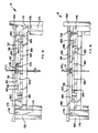
- the apparatus comprises a single frame generally referenced 64 to which the stations 2, 4, 6 and 8 are mounted.
- a main block 67 of the assembly 10, of which block the jaw 14 is a part, is connected to the piston rod 66 of a pneumatic piston and cylinder unit 68 for operating the jaw 12.
- An optical sensor 70 is provided in the block 67 for sensing the presence of a connector C1 or C2 in the assembly 10.
- the unit 68 is connected to the spindle of a motor 72 in the form of a rotary air cylinder for rotating the assembly 10.
- the motor 72 is fixed to a bracket 74 which is in turn secured, by way of a slide 75, to a horizontally shiftable subframe 76.
- the slide 75 is slidable in the direction of the Z-axis relative to the subframe 76.
- the subframe 76 is connected to a slide 78 mounted for horizontal sliding movement relative to the frame 64 on a slideway 80 ( Figures 4 and 5).
- the subframe 76 is fixed to the slide 78 by means of a fastening plate 82 on each side of the slide 78, and only one of which is shown.
- the assembly 10 is driven back and forth along the Z-axis by means of drive means (not shown).
- An amplifier 77 for sensor 70 is provided on the subframe 76.
- the slide 78 is driven in horizontal reciprocating motion, to move the assembly 10 along the axis Y to select a connector C1 or C2 according to the program, by means of a rack and pinion drive system (not shown) in a housing 84 on the frame 64.
- the subframe 76 comprises an end plate 86 containing a track, in which the push rod 26 is slidable by means of a piston and cylinder drive unit 88 fixed to a side plate 96 of the subframe 76 and having a piston rod 90 secured to a bracket 92 on the push rod 26, to drive it through a working stroke to transfer a connector C1 or C2 from the assembly 10 to the station 4.
- the piston rod 66 is connected to the block 67 by way of a bracket 94, so that the drive unit 68 is vertically offset from the path of movement of the push rod 26.
- the tracks 18 and 20 are mounted on plates 98 projecting laterally from the frame 64 and to which are secured guard plates 100 for the rows of connectors C1 and C2 on the tracks 18 and 20.
- Figures 5 and 7 show the assembly 10 in its advanced position to receive a connector C1 and
- Figures 6 and 8 show the assembly 10 in its retracted position along the axis Z ready for rotation about the axis X.
- the connector holder 30 is driven through a downward stroke to lower the nest 28 and through an upward return stroke to raise it, by means of a vertical piston and cylinder unit 102, also shown in Figure 4, the cover separating tool 34 and thus the ejector fingers 32 being driven by a horizontal piston and cylinder unit 104 which is shown in Figure 4.
- the unit 102 is mounted to the top of an elongate slideway block 106 defining a vertical slideway 108 for the connector holder 30 which is fixedly attached to the piston rod 110 of the unit 102.
- the block 106 is mounted in a subframe 112 to the bottom plate 114 of which is secured a horizontal slideway block 116 defining slideways 117 for the fingers 32.
- the cover-receiving nest mentioned above with reference to Figure 3, and which is not shown therein, is referenced 124 in Figures 9 and 10. It comprises a triangular cross section top plate 126, the upper end of which is pivotally attached to the block 106 by means of a pivot pin 128, the lower face 130 of the plate 126, and the upper face of a bottom block 132 fixed to the plate 114, defining upper and lower walls, respectively, of the nest 124.
- a slide 134 which is slidable horizontally in the block 132, has an arm 136 which is slidable in the nest 124 and is urged by springs (not shown) inwardly of the nest 124 to assume a normal position in which the free end face 138 of the arm 136, which face has therein a cover-receiving recess 140 is substantially coincident with the inner vertical wall 142 of the plate 126, which face 142 is formed with a vertical cover-receiving channel 144 communicating with the slideway 108 and extending parallel thereto.
- Figure 9 shows the connector holder 30 in its raised position, with a connector C1 in the nest 28 with its cover CO1 engaged in the recess 144 and abutting the surface 142, the piston rod 118 being in an advanced position so that the fingers 32 are retracted.
- Figure 10 shows the connector holder 30 in its lowered position and after the piston rod 118 has been retracted to cause the ejector fingers 32 to advance and thereby to separate the cover CO1 from the connector body CB1, and to drive the cover CO1 into the recess 140 of the arm 136, driving the arm 136, and thus the slide 134 rightwardly (as seen in Figure 10) so that the cover CO1 is received in the nest 124 and is releasably held in position between the end face 138 and the ejector fingers 32. Should a cover CO1 or CO2 jam in the nest 124, the plate 126 can be raised about the pivot pin 128 to allow the jammed cover to be removed from the nest 124.
- the push rods 36 and 38 are driven by a piston and cylinder unit 146 which, as shown in Figure 4, extends parallel to, and projects slightly to one side of, the unit 88.
- a guide track 148 communicates with the nest 28, in the lowered, Figure 10 position of the connector holder 30, a guide track 150 communicating with the space between the surface 138 of the arm 136 and the leading ends of the ejector fingers 32, when the ejector fingers 32 are in their Figure 10 position.
- the push rods 46 and 48 are driven by a horizontal piston and cylinder unit 152, to the piston rod 154 of which the rods 46 and 48 are connected, as shown in Figure 4.
- the turntable 44 is driven by a stepping motor 156 therebelow as indicated in broken lines in Figure 4.
- the push rods 46 and 48 run in guide channels 158 and 160, respectively, formed in a top plate 163 of the station 6, in an opening in which plate 136, the turntable 44 is rotatable, as best seen in Figure 11, by means of its motor 156, which lies below the plate 163.
- the grooves 40 and 42 are also aligned with respective connector body or connector cover guideways 162 and 164 formed in the plate 163 in alignment with the channels 158 and 160, each guideway 162 and 164 being cross-sectionally configured to receive either a connector body or its cover.
- the guideways 162 and 164 communicate with, and are aligned with, the nests 50 and 56, respectively, of the plates 52 and 58, respectively, at the station 8.
- the connector application station 8 comprises a subframe 164 having a central harness receiving vertical channel 166 to a base plate 168 of which are mounted on either side of the channel 166 a drive piston and cylinder unit 170 for the push plate 52 and a drive piston and cylinder unit 172 for the push plate 58.
- the piston rod 174 of each of these units is connected to one end of a link 176 by means of a pivot pin 178, the other end of the link 176 being pivotally connected by means of a pivot pin 180, to the respective push plate 52 or 58, near its end remote from the respective nest 50 or 56.
- the push plates 50 and 58 which have depending lugs 181 running in grooves 183 in push plate support brackets 182, on a top plate 184 of the subframe 164, are normally urged in a direction away from one another by springs 186 acting between the toggle links 176 and the brackets 182.
- the units 170 and 172 are actuated sequentially to advance their piston rods 174 to rotate the links 176 so as to drive the push plates 52 and 58 towards one another.
- the drive unit for the push plate carrying the connector cover is first actuated so that the cable FFC is enclosed by the cover, the drive unit for the push plate carrying the connector body being actuated subsequently, to drive it into the cover.
- the cable severing blade 60 which is mounted above the push plates 52 and 58, and which is slidable along a cross plate 188 mounted between side plates 190 of the subframe 164, is arranged to be driven towards and away from the anvil 62 by means of a piston and cylinder drive unit 192 having a piston rod 194 connected to the blade 60 by means of a linkage 196.
- the unit 192 is secured to a subframe 198 on the plate 188 from which extends centrally of the subframe 198, a vertical cable guide 200 aligned with the channel 166, for guiding the cable FFC between the blade 60 and anvil 62 and between the push plates 52 and 58.
- a cable feed stepping motor 202 (Figures 4 and 13), the spindle of which is connected to the shaft 204 ( Figure 12) of a driving gear wheel 206 which drives a further gear wheel 208 meshing with a gear wheel 210 fixed to a cable drive roller 212 having a shaft 214 and projecting through a slot 216 in the guide 200 to engage one side of the cable FFC extending therethrough.
- the shaft 214 of the roller 212 is mounted for rotation in one end of a bifurcated pusher lever 218, the other end of which is pivotally mounted to the subframe 198.
- roller 212 Opposite to the roller 212 in the subframe 198, is mounted an idle roller 220, also projecting into the slot 216 to engage the other side of the cable FFC.
- the roller 212 is urged against the cable FFC in driving relationship therewith, by the spring 222 which urges the lever 218 in a clockwise (as seen in Figure 12) sense, whereby the cable FFC is driven downwardly each time the motor 204 is run.
- sensors 224 ( Figures 7 and 8) for monitoring the horizontal position of the slide 75
- sensors 226 ( Figures 9 and 10) for monitoring the vertical position of the connector holder 30
- sensors 228 for monitoring the horizontal positions of the push rods 32
- sensors 230 for monitoring the horizontal positions of the push plates 52 and 58.
Landscapes
- Engineering & Computer Science (AREA)
- Manufacturing & Machinery (AREA)
- Manufacturing Of Electrical Connectors (AREA)
Abstract
Claims (10)
- Appareil pour connecter aux conducteurs d'un câble plat (FFC) à conducteurs multiples des connecteurs électriques (C1 et C2) ayant des bornes électriques (T1 et T2) pourvues de parties (RP) de réception de conducteurs du câble, l'appareil comportant une presse (54) qui peut être actionnée pour poser lesdits connecteurs sur le câble (FFC) en insérant les conducteurs du câble dans lesdites parties (RP) de réception de conducteurs, des moyens (202) destinés à faire avancer le câble (FFC) par intermittence à travers la presse (54), et des moyens (10 et 44) d'orientation de connecteurs destinés à amener les connecteurs (C1 et C2) à la presse (54) dans plusieurs orientations différentes et comprenant un premier élément (10) de réception de connecteur qui peut être tourné pour déterminer une première orientation de chaque connecteur (C1 et C2) ; caractérisé par des premiers moyens de transfert (26, 36, 38) destinés à transférer chaque connecteur (C1 et C2) dudit premier élément (10) de réception de connecteur lorsque le connecteur (C1 ou C2) a été orienté par celui-ci vers un second élément (44) de réception de connecteur qui peut être tourné pour déterminer une seconde orientation du connecteur (C1 ou C2) ; et par des seconds moyens de transfert (46 et 48) destinés à transférer le connecteur (C1 ou C2) depuis le second élément (44) de réception de connecteur, lorsque le connecteur (C1 ou C2) a été orienté par celui-ci, jusqu'à la presse (54).
- Appareil selon la revendication 1, caractérisé en ce que le premier élément de réception de connecteur se présente sous la forme de deux mâchoires (12 et 14) montées de façon à pouvoir tourner sur un bâti (64) de l'appareil et pouvant être tournées par des moyens d'entraînement (72) situés sur ledit bâti (64) ; et en ce que le second élément de réception de connecteur se présente sous la forme d'un plateau tournant (44) qui est également monté de façon à pouvoir tourner sur le bâti (64) et qui comporte des moyens d'entraînement (156) situés sur le bâti (64), lesdites mâchoires (12 et 14) étant disposées de façon à orienter les connecteurs (C1 ou C2) en bout, et ledit plateau tournant (44) servant à orienter lesdits connecteurs (C1 ou C2) de manière que certains fassent saillie d'un côté du câble (FFC) et que d'autres fassent saillie de l'autre côté du câble lorsque les connecteurs (C1 ou C2) ont été posés sur le câble (FFC) par la presse (54).
- Appareil selon la revendication 1 ou 2, caractérisé en ce que ledit premier élément (10) de réception de connecteur peut être translaté transversalement à plusieurs rangées de connecteurs électriques différents (C1 et C2) avancés dans une disposition parallèle vers le premier élément (10) de réception de connecteur, afin de sélectionner un connecteur (C1 ou C2) parmi l'une quelconque desdites rangées pour le poser sur le câble (FFC).
- Appareil selon la revendication 1, 2 ou 3, à utiliser avec des connecteurs (C1 et C2) comportant chacun un corps (CB1 ou CB2) de connecteur disposé de façon à s'accoupler avec un capot (CO1 ou CO2) comportant des moyens (WP) d'enfoncement de conducteurs destinés à introduire à force les conducteurs du câble (FFC) dans les parties (RP) de réception de conducteur du câble des bornes (T1 et T2) ; caractérisé en ce que les corps de connecteurs (CB1 et CB2) sont amenés au premier élément (10) de réception de connecteur avec les capots (CO1 et CO2) partiellement accouplés avec eux, un poste (4) de séparation de capots étant prévu entre les deux éléments (10 et 44) de réception de connecteurs pour séparer les capots (CO1 et CO2) des corps de connecteur (CB1 et CB2), le second élément (44) de réception de connecteur présentant deux évidements parallèles (40 et 42) destinés chacun à recevoir un corps de connecteur (CB1 ou CB2) ou un capot (CO1 ou CO2), la presse (54) comportant deux éléments (52 et 58) de pose de connecteur disposés de part et d'autre du câble (FFC) et agencés chacun de façon à recevoir un corps de connecteur (CB1 ou CB2) ou un capot de connecteur (CO1 ou CO2), comme déterminé par ladite position angulaire du second élément (44) de réception de connecteur.
- Appareil selon la revendication 4, caractérisé en ce que le poste (4) de séparation de capot comprend un support (30) de connecteur monté de façon à effectuer un mouvement alternatif axial et ayant un premier logement (28), destiné à recevoir un connecteur électrique (C1 ou C2) transféré depuis ledit premier élément (10) de réception de connecteur par un premier élément de transfert (26) desdits premiers moyens de transfert (26, 36, 38), dans une première position axiale dudit support (30) de connecteur, des moyens (32) étant prévus pour séparer, dans une seconde position axiale du support (30) de conencteur, le capot (CO1 ou CO2) du corps de connecteur (CB1 ou CB2) dans ledit premier logement (28) et pour amener le capot dans un deuxième logement (124) espacé du support (30) de connecteur à angle droit avec sa direction de déplacement, lesdits évidements (40 et 42) dans ledit second élément (44) de réception de connecteur étant alignés chacun avec l'un, respectif, desdits premier et deuxième logements (28 et 124) dans une position angulaire donnée dudit second élément (44) de réception de connecteur pour le transfert du corps de connecteur (CB1 ou CB2) et du capot de connecteur (CO1 ou CO2) par des seconds éléments de transfert (36 et 38) desdits premiers moyens de transfert (26, 36, 38) depuis leurs logements respectifs (28 et 124) jusque dans certains, respectifs, des évidements (40 et 42) du second élément (44) de réception de connecteur.
- Appareil selon la revendication 5, caractérisé en ce que ledit premier élément de transfert se présente sous la forme d'un poussoir (26) ayant une unité d'entraînement (88) destinée à le faire avancer pour entraîner un connecteur (C1 ou C2) situé dans les premiers moyens (10) de réception de connecteur jusque dans ledit premier logement (28), dans ladite première position axiale du support (30) de connecteur, lesdits seconds éléments de transfert comprenant une première paire de poussoirs (36 et 38) ayant des moyens d'entraînement (146) destinés à les faire avancer pour entraîner un corps de connecteur (CB1 ou CB2) situé dans ledit premier logement (28) et un capot de connecteur (CO1 ou CO2) situé dans ledit deuxième logement (124), chacun jusque dans un évidement respectif (40 ou 42) du second élément (44) de réception de connecteur, lesdits seconds moyens de transfert comprenant une seconde paire de poussoirs (46 et 48) ayant des moyens d'entraînement (152) destinés à les faire avancer pour entraîner un corps de connecteur (CB1 ou CB2) situé dans un évidement (40 ou 42) du second élément (44) de réception de connecteur et un capot (CO1 ou CO2) de connecteur dans l'autre évidement (40 ou 42) de cet élément dans un logement respectif (50 ou 56) de l'un, respectif, desdits éléments (52 et 58) de pose de connecteur.
- Appareil selon la revendication 5 ou 6, caractérisé en ce que ledit poste de séparation de capot comprend une paire de doigts éjecteurs (32) disposés de façon à chevaucher ledit support (30) de connecteur dans sa seconde position axiale et ayant une unité d'entraînement (104) destinée à faire avancer lesdits doigts (32) pour séparer le capot (CO1 ou CO2) du corps de connecteur (CB1 ou CB2) dans ledit premier logement (28) dans ladite seconde position axiale du support (30) de connecteur et pour entraîner ledit capot (CO1 ou CO2) contre un bras (136), rappelé par ressort, faisant saillie dans ledit second logement (124) afin de rétracter le bras (136) vers l'extérieur de son logement (124) pour aligner le capot (CO1 ou CO2) situé dans le second logement (124) avec le second élément respectif (38) de transfert.
- Appareil selon l'une quelconque des revendications précédentes, caractérisé en ce que le premier élément (10) de réception de connecteur est monté sur un coulisseau (75) destiné à rapprocher et éloigner le premier élément (10) de réception de connecteur de rangées parallèles de premiers et seconds connecteurs (C1 et C2) montés chacun sur une première longueur de ruban adhésif (AT1 ou AT2), ledit coulisseau (75) étant relié à un cylindre pneumatique rotatif (72) destiné à faire tourner une unité (68) d'entraînement à piston et cylindre pour faire tourner le premier élément (10) de réception de connecteur autour de l'axe de ladite tige de piston (66), le cylindre pneumatique rotatif (72) étant relié à des moyens d'entraînement (84) destinés à le translater jusqu'en alignement avec l'une, choisie, desdites rangées de connecteurs (C1 et C2), des moyens étant prévus pour faire avancer chaque longueur de ruban (AT1 et AT2) vers le premier élément (10) de réception de connecteur dans une position avancée du coulisseau (75) afin de placer un connecteur (C1 ou C2) de la rangée respective dans le premier élément (10) de réception de connecteur.
- Appareil selon l'une quelconque des revendications 4 à 7, caractérisé en ce que les éléments (50 et 58) de pose de connecteurs de la presse (54) sont pourvus de moyens d'entraînement distincts (170 et 172) destinés à entraîner sélectivement l'un desdits éléments (52 et 58) de pose vers le câble (FFC) avant l'autre (52 ou 58) de ces éléments.
- Appareil selon l'une quelconque des revendications précédentes, caractérisé en ce que lesdits moyens d'avance de câble comprennent un moteur pas à pas (202) accouplé en entraînement à un rouleau (212) d'entraînement de câble au moyen d'un train d'engrenages (204, 208) monté sur un bras (218) rappelé par ressort rappelant ledit rouleau d'entraînement (212) contre le câble (FFC), afin qu'il soit engagé à frottement entre ledit rouleau d'entraînement (212) et un rouleau fou (220) situé sur l'autre côté du câble (FFC).
Applications Claiming Priority (2)
| Application Number | Priority Date | Filing Date | Title |
|---|---|---|---|
| GB8725682 | 1987-11-03 | ||
| GB878725682A GB8725682D0 (en) | 1987-11-03 | 1987-11-03 | Connecting electrical connectors to cable |
Publications (2)
| Publication Number | Publication Date |
|---|---|
| EP0348448A1 EP0348448A1 (fr) | 1990-01-03 |
| EP0348448B1 true EP0348448B1 (fr) | 1993-06-02 |
Family
ID=10626326
Family Applications (1)
| Application Number | Title | Priority Date | Filing Date |
|---|---|---|---|
| EP88908871A Expired - Lifetime EP0348448B1 (fr) | 1987-11-03 | 1988-09-19 | Appareil de connexion de connecteurs electriques a un cable |
Country Status (6)
| Country | Link |
|---|---|
| EP (1) | EP0348448B1 (fr) |
| JP (1) | JPH02502052A (fr) |
| KR (1) | KR890702298A (fr) |
| DE (1) | DE3881512T2 (fr) |
| GB (1) | GB8725682D0 (fr) |
| WO (1) | WO1989004557A1 (fr) |
Families Citing this family (1)
| Publication number | Priority date | Publication date | Assignee | Title |
|---|---|---|---|---|
| US5122079A (en) * | 1991-04-23 | 1992-06-16 | Amp Incorporated | Multiple conductor cable connector with towers |
Family Cites Families (3)
| Publication number | Priority date | Publication date | Assignee | Title |
|---|---|---|---|---|
| US4561178A (en) * | 1984-10-25 | 1985-12-31 | Amp Incorporated | Apparatus for installing connectors on flat cable having automatic connector delivery system and selective orientation feature for the connectors |
| US4675995A (en) * | 1985-02-19 | 1987-06-30 | Burndy Corporation | Compact semi-automatic cable assembly system |
| US4584757A (en) * | 1985-02-25 | 1986-04-29 | Amp Incorporated | Assembly for connecting electrical connectors to flat multiconductor cable |
-
1987
- 1987-11-03 GB GB878725682A patent/GB8725682D0/en active Pending
-
1988
- 1988-09-19 DE DE88908871T patent/DE3881512T2/de not_active Expired - Fee Related
- 1988-09-19 JP JP63508098A patent/JPH02502052A/ja active Pending
- 1988-09-19 WO PCT/US1988/003202 patent/WO1989004557A1/fr not_active Ceased
- 1988-09-19 EP EP88908871A patent/EP0348448B1/fr not_active Expired - Lifetime
-
1989
- 1989-06-30 KR KR1019890701218A patent/KR890702298A/ko not_active Withdrawn
Also Published As
| Publication number | Publication date |
|---|---|
| KR890702298A (ko) | 1989-12-23 |
| JPH02502052A (ja) | 1990-07-05 |
| EP0348448A1 (fr) | 1990-01-03 |
| WO1989004557A1 (fr) | 1989-05-18 |
| GB8725682D0 (en) | 1987-12-09 |
| DE3881512T2 (de) | 1993-12-16 |
| DE3881512D1 (de) | 1993-07-08 |
Similar Documents
| Publication | Publication Date | Title |
|---|---|---|
| US4653159A (en) | Flexible automated manufacturing system | |
| CA1269519A (fr) | Dispositif d'assemblage de faisceaux de cablage | |
| CA1077685A (fr) | Dispositif d'insertion de fils conducteurs | |
| CA1049236A (fr) | Dispositif de reagencement des fils, passant d'un ordre numerique defini au hasard a un ordre numerique determine d'avance | |
| EP0778587A2 (fr) | Fil électrique plat pour faisceau de fils et méthode et appareil de sa production | |
| EP0196740B1 (fr) | Ensemble pour connecter des connecteurs électriques à un câble | |
| US4970778A (en) | Apparatus for connecting electrical connectors to cable | |
| US4566164A (en) | Apparatus for connecting electrical connectors to flat multi-conductor cable | |
| EP0040491B1 (fr) | Appareil pour insérer des terminaux électriques dans un boîtier d'un connecteur électrique | |
| EP0101488B1 (fr) | Procede et dispositif permettant d'appliquer des blocs connecteurs en deux parties a un cable a conducteurs multiples | |
| CA1257465A (fr) | Systeme souple de fabrication automatisee | |
| EP0215809B1 (fr) | Etui de transfert de connecteurs electriques | |
| EP0206464B1 (fr) | Appareil pour fabriquer des harnais de câbles électriques | |
| US4525927A (en) | Method and apparatus for connecting an insulating housing of a connector and a cover | |
| JPS6012687A (ja) | コ−ド製造装置 | |
| EP0242113B1 (fr) | Méthode et appareil pour faire des faisceaux de câbles-rubans | |
| EP0041815B1 (fr) | Appareil et méthode pour fabriquer des pièces de harnais de câbles en série | |
| WO1989004557A1 (fr) | Appareil de connexion de connecteurs electriques a un cable | |
| CA1135485A (fr) | Dispositif et methode d'insertion de bornes, portees sur une bande, dans les orifices d'une piece | |
| US4623293A (en) | Apparatus for orientating elongate bodies | |
| US4650391A (en) | Electrical connector pick-up station | |
| EP0168141B1 (fr) | Appareil et méthode pour assembler des fils munis de terminaux pour fabriquer des faisceaux | |
| US4589200A (en) | Applicator for applying an electrical connector to a cable | |
| EP0231617A1 (fr) | Appareil pour la fixation d'un câble électrique à un connecteur électrique | |
| WO1995034926A1 (fr) | Appareil et procede de production de faisceaux electriques |
Legal Events
| Date | Code | Title | Description |
|---|---|---|---|
| PUAI | Public reference made under article 153(3) epc to a published international application that has entered the european phase |
Free format text: ORIGINAL CODE: 0009012 |
|
| AK | Designated contracting states |
Kind code of ref document: A1 Designated state(s): AT BE CH DE FR GB IT LI NL SE |
|
| 17P | Request for examination filed |
Effective date: 19891116 |
|
| 17Q | First examination report despatched |
Effective date: 19920616 |
|
| RAP1 | Party data changed (applicant data changed or rights of an application transferred) |
Owner name: THE WHITAKER CORPORATION |
|
| RBV | Designated contracting states (corrected) |
Designated state(s): CH DE FR GB IT LI NL SE |
|
| GRAA | (expected) grant |
Free format text: ORIGINAL CODE: 0009210 |
|
| AK | Designated contracting states |
Kind code of ref document: B1 Designated state(s): CH DE FR GB IT LI NL SE |
|
| ITF | It: translation for a ep patent filed | ||
| REF | Corresponds to: |
Ref document number: 3881512 Country of ref document: DE Date of ref document: 19930708 |
|
| ET | Fr: translation filed | ||
| PLBE | No opposition filed within time limit |
Free format text: ORIGINAL CODE: 0009261 |
|
| STAA | Information on the status of an ep patent application or granted ep patent |
Free format text: STATUS: NO OPPOSITION FILED WITHIN TIME LIMIT |
|
| 26N | No opposition filed | ||
| EAL | Se: european patent in force in sweden |
Ref document number: 88908871.2 |
|
| PGFP | Annual fee paid to national office [announced via postgrant information from national office to epo] |
Ref country code: SE Payment date: 19960819 Year of fee payment: 9 |
|
| PG25 | Lapsed in a contracting state [announced via postgrant information from national office to epo] |
Ref country code: SE Free format text: LAPSE BECAUSE OF NON-PAYMENT OF DUE FEES Effective date: 19970920 |
|
| EUG | Se: european patent has lapsed |
Ref document number: 88908871.2 |
|
| PGFP | Annual fee paid to national office [announced via postgrant information from national office to epo] |
Ref country code: GB Payment date: 19980806 Year of fee payment: 11 |
|
| PGFP | Annual fee paid to national office [announced via postgrant information from national office to epo] |
Ref country code: FR Payment date: 19980902 Year of fee payment: 11 |
|
| PGFP | Annual fee paid to national office [announced via postgrant information from national office to epo] |
Ref country code: DE Payment date: 19980928 Year of fee payment: 11 |
|
| PGFP | Annual fee paid to national office [announced via postgrant information from national office to epo] |
Ref country code: CH Payment date: 19981013 Year of fee payment: 11 |
|
| PGFP | Annual fee paid to national office [announced via postgrant information from national office to epo] |
Ref country code: NL Payment date: 19990630 Year of fee payment: 12 |
|
| PG25 | Lapsed in a contracting state [announced via postgrant information from national office to epo] |
Ref country code: GB Free format text: LAPSE BECAUSE OF NON-PAYMENT OF DUE FEES Effective date: 19990919 |
|
| PG25 | Lapsed in a contracting state [announced via postgrant information from national office to epo] |
Ref country code: LI Free format text: LAPSE BECAUSE OF NON-PAYMENT OF DUE FEES Effective date: 19990930 Ref country code: CH Free format text: LAPSE BECAUSE OF NON-PAYMENT OF DUE FEES Effective date: 19990930 |
|
| GBPC | Gb: european patent ceased through non-payment of renewal fee |
Effective date: 19990919 |
|
| REG | Reference to a national code |
Ref country code: CH Ref legal event code: PL |
|
| PG25 | Lapsed in a contracting state [announced via postgrant information from national office to epo] |
Ref country code: FR Free format text: LAPSE BECAUSE OF NON-PAYMENT OF DUE FEES Effective date: 20000531 |
|
| PG25 | Lapsed in a contracting state [announced via postgrant information from national office to epo] |
Ref country code: DE Free format text: LAPSE BECAUSE OF NON-PAYMENT OF DUE FEES Effective date: 20000701 |
|
| REG | Reference to a national code |
Ref country code: FR Ref legal event code: ST |
|
| PG25 | Lapsed in a contracting state [announced via postgrant information from national office to epo] |
Ref country code: NL Free format text: LAPSE BECAUSE OF NON-PAYMENT OF DUE FEES Effective date: 20010401 |
|
| NLV4 | Nl: lapsed or anulled due to non-payment of the annual fee |
Effective date: 20010401 |
|
| PG25 | Lapsed in a contracting state [announced via postgrant information from national office to epo] |
Ref country code: IT Free format text: LAPSE BECAUSE OF NON-PAYMENT OF DUE FEES Effective date: 20050919 |