EP0348588A2 - Laminoir à pas de pèlerin - Google Patents
Laminoir à pas de pèlerin Download PDFInfo
- Publication number
- EP0348588A2 EP0348588A2 EP89100772A EP89100772A EP0348588A2 EP 0348588 A2 EP0348588 A2 EP 0348588A2 EP 89100772 A EP89100772 A EP 89100772A EP 89100772 A EP89100772 A EP 89100772A EP 0348588 A2 EP0348588 A2 EP 0348588A2
- Authority
- EP
- European Patent Office
- Prior art keywords
- spindle
- rolling mill
- dogs
- pilgrim
- sleeve
- Prior art date
- Legal status (The legal status is an assumption and is not a legal conclusion. Google has not performed a legal analysis and makes no representation as to the accuracy of the status listed.)
- Ceased
Links
Images

Classifications
-
- B—PERFORMING OPERATIONS; TRANSPORTING
- B21—MECHANICAL METAL-WORKING WITHOUT ESSENTIALLY REMOVING MATERIAL; PUNCHING METAL
- B21B—ROLLING OF METAL
- B21B21/00—Pilgrim-step tube-rolling, i.e. pilger mills
- B21B21/04—Pilgrim-step feeding mechanisms
Definitions
- This invention relates to a pilgrim-process rolling mill of a type comprising a spindle coaxially fitted to a piston rod of a piston from a hydropneumatic box
- a crawl-process rolling mill basically comprises, in addition to two work rolls having peculiar eccentric profiles, a mandrel, a mandrel-breaker bush associated with the mandrel, a spindle fitted to a piston from a hydropneumatic box, and a drive means for rotating the mandrel.
- Pilgrim-process rolling mills are usually employed for hot rolling seamless pipes; in particular, a current trend in the application of such mills favors the production of large size pipes in small but neatly differentiated batches, which leads to the need for frequent exchange of the mill tooling and particularly of the mandrels and spindles.
- Another connection conventionally employed between the spindle and the hydropneumatic box is the so-called oil pressure type, which consists basically of inducing a temporary expansion of the spindle in a radial direction by means of pressurized oil, thereby enabling the spindle to fit over the piston rod.
- oil pressure connection is quite a reliable one, especially when compared to the threaded half-bush, but requires skilled labor, and the spindle mounting and removing times still are too long with it.
- the problem underlying this invention is to provide a successive-process rolling mill wherein the connection of the spindle to the piston rod from the hydropneumatic box is a secure and reliable one, and makes for quick replaceability of the spindle.
- a rolling mill as specified above being characterized in that it includes a bayonet joint between said piston rod and the spindle.
- the numeral 1 comprehensively designates a mitoscopy mill for seamless hot rolling a pipe 2.
- the rolling mill 1 comprises a conventional hydropneumatic box 3 having a piston 4 movable along a horizontal rolling axis X-X on guides 5 and driven to rotate about its own axis by a drive means, not shown, associated with said hydropneumatic box 3.
- the piston 4 has a piston rod 6 wherewith a spindle 7 is associated axially.
- a substantially cradle-like portion 8 of the spindle 7 accommodates a tang 9 of a mandrel 10 extending along the axis X-X, with the pipe 2 to be rolled partway fitted over it.
- a pusher means 12 acting on the sprung means 11 to release the tang 9 and enable it to be removed from the cradle seat 8 in the spindle 7.
- the reference numeral 13 designates a mandrel-breaker bush associated with the mandrel 10 and adapted to release the pipe 2 from the mandrel 10 on completion of the rolling process.
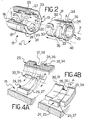
- the vocational-process rolling mill 1 is provided with a bayonet joint 14 between the spindle 7 and the rod 6
- the bayonet joint 14 comprises a sleeve 15 which extends in the direction of the axis X-X and has a first section 16 of a smaller diameter next to the box 3, being fitted under oil pressure over a portion 17 of the rod 6 having a matching diameter dimension, and a second section 18 of larger diameter next to the spindle 7.
- a substantially cup-shaped seat 19 having a circular inlet 20 facing toward the spindle 7, a bottom 21 remote from the inlet 20 and from which an end portion 22 of the rod 6 juts out into the seat 19, and a circumferential inner wall 23.
- a respective side wall 26, 27 facing the inlet 20 is set at predetermined angle alpha which would be selected in relation to the material used to manufacture the sleeve 8, the type of the lubricant employed, and the dimensions of the rolling mill.
- the angle alpha is approximately 5°.
- the dogs 24, 25 will have, in plan view, a profile tapering in a common direction that, in the example shown, is counterclockwise as the inlet 20 sees the dogs 24, 25 .
- Indicated at 28 is a polygonal contour formed peripherally on the exterior of the sleeve 15 close to the inlet 20 and adapted to be engaged by a spanner or the like tightening means.
- the bayonet joint 14 further comprises a tang 29 formed integrally with the spindle 7 in line with the cradle seat 8.
- the tang 29 has a substantially cylindrical shape and a suitable diameter to allow it to fit in between the dogs 24 and 25 on the sleeve 15. That tang 29 is provided on its exterior with a pair of first dogs 30, 31 located diametrically opposite each other in the proximity of an end 32 of the tang facing the sleeve 15 and extending a predetermined distance around the circumference of the tang, and a pair of second dogs 33, 34, also arranged diametrically opposite each other, which are aligned to the first dogs 30, 31 along generatrix lines of the cylindrical tang 29 and set apart therefrom.
- the spacing of the first dogs 30, 31, which spacing is equal to the spacing of the second dogs 33, 34 should be larger than the length of the dogs 24, 25 on the sleeve 15 in the circumferential direction.
- a respective side wall 35, 36 of the second dogs 33, 34, which walls face the first dogs 30, 31, respectively, is set at the same angle alpha as the dogs 24 and 25.
- each first dog 30, 31 and its corresponding second dog 33, 34 there is defined a tapering seat 37, 38 adapted to receive in press fit relationship a dog, 24, 25, of the sleeve 15.
- the length of the tapering seats 37 and 38 along the circumferential direction is equal to the corresponding length of the dogs 24 and 25.
- the first dogs 30, 31 and second dogs 33, 34 are advantageously formed integrally with the tang 29.
- a cylindrical notch 39 is formed in the end 32 of the tang 29 to receive the end portion 22 of the rod 6 therein.
- the reference numeral 40 designates a polygonal contour formed peripherally around the tang 29 of the spindle 7 and also intended, like the similar contour 28 on the sleeve 15, for engagement by a spanner or the like tool, not shown.
- the spindle 7 is first aligned, using a conventional crane not shown, to the sleeve 15 so that it coincides with the horizontal rolling axis X-X, the tang 29 being so oriented as to prevent the first dogs 30, 31, and hence the second dogs 33, 34, from interfering with the dogs 24, 25 on the sleeve 15 on insertion of the tang 29 into the sleeve.
- the tang 29 of the spindle 7 is then driven to bottom out in the cup-shaped seat 19 of the sleeve 15, and a preliminary rotary motion is next imparted on the spindle to engage the dogs 24 and 25 in the tapering seats 37 and 38 in the tang 29.
- the spindle 7 will be supported on the sleeve 15, in turn rigid with the hydropneumatic box 3, and can therefore be released from the crane.
- the spindle 7 is released for rotation by applying a spanner to the polygonal contour 40 of the tang 29, and by operating the hydraulic motor conventionally provided in the hydropneumatic box 3 for adjusting the angular setting of the piston 4, the dogs 24, 25 are driven into their respective tapering seats 37 and 38 to thus complete the spindle 7 mounting to the piston rod 6.
- a spanner is applied to the polygonal contour 40 of the spindle 7, and after that the bayonet joint 14 is shaken loose by a maul blow on the spanner, possibly while holding the sleeve 15 with another spanner applied to the polygonal contour 28.
- the spindle may be mounted by suitably acting with appropriate spanners on the polygonal contours 28 and 40.
- the coupling of the spindle to the hydropneumatic box is, moreover, quite reliable. It has been beneficial in this respect to provide the slleve dogs with sloping walls and the respective seats with matching shapes in that, while this further facilitates the spindle mounting and removing operations, it also enables any play developed from the dog wear to be taken up by driving the sleeve dogs deeper into the tapering seats to ensure that a press fit is maintained.
Landscapes
- Engineering & Computer Science (AREA)
- Mechanical Engineering (AREA)
- Crushing And Grinding (AREA)
- Shafts, Cranks, Connecting Bars, And Related Bearings (AREA)
Applications Claiming Priority (2)
| Application Number | Priority Date | Filing Date | Title |
|---|---|---|---|
| IT2117988 | 1988-06-30 | ||
| IT21179/88A IT1217980B (it) | 1988-06-30 | 1988-06-30 | Laminatoio a passo di pellegrino |
Publications (2)
| Publication Number | Publication Date |
|---|---|
| EP0348588A2 true EP0348588A2 (fr) | 1990-01-03 |
| EP0348588A3 EP0348588A3 (fr) | 1990-08-08 |
Family
ID=11177973
Family Applications (1)
| Application Number | Title | Priority Date | Filing Date |
|---|---|---|---|
| EP89100772A Ceased EP0348588A3 (fr) | 1988-06-30 | 1989-01-18 | Laminoir à pas de pèlerin |
Country Status (2)
| Country | Link |
|---|---|
| EP (1) | EP0348588A3 (fr) |
| IT (1) | IT1217980B (fr) |
Cited By (3)
| Publication number | Priority date | Publication date | Assignee | Title |
|---|---|---|---|---|
| EP0348595A3 (fr) * | 1988-06-30 | 1991-09-25 | INNSE INNOCENTI ENGINEERING S.p.A. | Broche pour laminoir à pas de pèlerin |
| EP0348596A3 (fr) * | 1988-06-30 | 1991-10-02 | INNSE INNOCENTI ENGINEERING S.p.A. | Laminoir à pas de pèlerin pour laminage à chaud de tubes |
| CN103586283A (zh) * | 2013-11-22 | 2014-02-19 | 四川三洲特种钢管有限公司 | 一种芯棒锁紧机构 |
Family Cites Families (2)
| Publication number | Priority date | Publication date | Assignee | Title |
|---|---|---|---|---|
| DE7141104U (de) * | 1971-10-26 | 1972-08-24 | Mannesmann Meer Ag | Walzdorn fur Lochschragwalzwerke |
| DE2347385A1 (de) * | 1973-09-17 | 1975-03-27 | Mannesmann Meer Ag | Einrichtung zum verbinden und loesen eines dornes mit bzw. von einer dornstange fuer ein schraegwalzwerk |
-
1988
- 1988-06-30 IT IT21179/88A patent/IT1217980B/it active
-
1989
- 1989-01-18 EP EP89100772A patent/EP0348588A3/fr not_active Ceased
Cited By (4)
| Publication number | Priority date | Publication date | Assignee | Title |
|---|---|---|---|---|
| EP0348595A3 (fr) * | 1988-06-30 | 1991-09-25 | INNSE INNOCENTI ENGINEERING S.p.A. | Broche pour laminoir à pas de pèlerin |
| EP0348596A3 (fr) * | 1988-06-30 | 1991-10-02 | INNSE INNOCENTI ENGINEERING S.p.A. | Laminoir à pas de pèlerin pour laminage à chaud de tubes |
| CN103586283A (zh) * | 2013-11-22 | 2014-02-19 | 四川三洲特种钢管有限公司 | 一种芯棒锁紧机构 |
| CN103586283B (zh) * | 2013-11-22 | 2015-08-19 | 四川三洲特种钢管有限公司 | 一种芯棒锁紧机构 |
Also Published As
| Publication number | Publication date |
|---|---|
| IT8821179A0 (it) | 1988-06-30 |
| IT1217980B (it) | 1990-03-30 |
| EP0348588A3 (fr) | 1990-08-08 |
Similar Documents
| Publication | Publication Date | Title |
|---|---|---|
| AU2023201048B2 (en) | Pipe receiving assembly for a pipe grooving device | |
| US6666062B2 (en) | Pipe preparation device | |
| CA2103928C (fr) | Organe de transmission du couple et methode de fabrication | |
| CA2725746C (fr) | Procede de fabrication d'un anneau | |
| CA1172878A (fr) | Outil de forgeage a froid de tubes a profil interieur | |
| US4667498A (en) | Method and apparatus of making gelatine capsule forming pins having a rounded locking groove | |
| CA2877173C (fr) | Formation de cannelures helicoidales | |
| US4758149A (en) | Capsule forming pin having a burnish-hardened surface | |
| EP3504014B1 (fr) | Procédé pour produire un corps à symétrie de rotation sans enlèvement de copeaux à partir d'un flan de tôle | |
| US3779064A (en) | Process and apparatus for calibrating and surfacing tubes | |
| US4829800A (en) | Method and apparatus for cold sizing a round workpiece having multiple diameters | |
| RU2152283C1 (ru) | Способ изготовления угольника | |
| EP1190794B1 (fr) | Méthode pour usiner une pièce et mandrin avec pointe à centrer la mise en oeuvre de ce procédé | |
| US20010015084A1 (en) | Forming machine | |
| US4428222A (en) | Cold forging mandrel with threads | |
| US3292403A (en) | Embossing mill registration locking device | |
| US1383747A (en) | Method of making flexible sleeve-valves | |
| US4712410A (en) | Method and apparatus for cold sizing a round workpiece having multiple diameters | |
| RU2216423C2 (ru) | Способ производства деталей типа цилиндры методом ротационной вытяжки и устройство для его осуществления | |
| JPH055244U (ja) | 圧延機用ロール工具の取付装置 | |
| SU1222376A1 (ru) | Устройство дл раскатки осесимметричных изделий | |
| JPS6013534Y2 (ja) | 圧延機用ロ−ルチヨツク装置 | |
| EP0114108A2 (fr) | Procédé pour laminer à froid une pièce circulaire à usiner à plusieurs diamètres | |
| JP2001001095A (ja) | ローラ式転造丸ダイス及びその製造方法 | |
| DE10238625B4 (de) | Spanabtragende Drückmaschine |
Legal Events
| Date | Code | Title | Description |
|---|---|---|---|
| PUAI | Public reference made under article 153(3) epc to a published international application that has entered the european phase |
Free format text: ORIGINAL CODE: 0009012 |
|
| AK | Designated contracting states |
Kind code of ref document: A2 Designated state(s): AT BE CH DE ES FR GB GR IT LI LU NL SE |
|
| PUAL | Search report despatched |
Free format text: ORIGINAL CODE: 0009013 |
|
| AK | Designated contracting states |
Kind code of ref document: A3 Designated state(s): AT BE CH DE ES FR GB GR IT LI LU NL SE |
|
| 17P | Request for examination filed |
Effective date: 19901218 |
|
| 17Q | First examination report despatched |
Effective date: 19911112 |
|
| RAP1 | Party data changed (applicant data changed or rights of an application transferred) |
Owner name: INNSE INNOCENTI ENGINEERING S.P.A. |
|
| RAP1 | Party data changed (applicant data changed or rights of an application transferred) |
Owner name: INNSE INNOCENTI ENGINEERING S.P.A. |
|
| STAA | Information on the status of an ep patent application or granted ep patent |
Free format text: STATUS: THE APPLICATION HAS BEEN REFUSED |
|
| 18R | Application refused |
Effective date: 19931001 |