EP0348589A2 - Pilgerwalzwerk - Google Patents
Pilgerwalzwerk Download PDFInfo
- Publication number
- EP0348589A2 EP0348589A2 EP89100773A EP89100773A EP0348589A2 EP 0348589 A2 EP0348589 A2 EP 0348589A2 EP 89100773 A EP89100773 A EP 89100773A EP 89100773 A EP89100773 A EP 89100773A EP 0348589 A2 EP0348589 A2 EP 0348589A2
- Authority
- EP
- European Patent Office
- Prior art keywords
- mandrel
- seat
- rolling mill
- spindle
- cradle
- Prior art date
- Legal status (The legal status is an assumption and is not a legal conclusion. Google has not performed a legal analysis and makes no representation as to the accuracy of the status listed.)
- Withdrawn
Links
Images


Classifications
-
- B—PERFORMING OPERATIONS; TRANSPORTING
- B21—MECHANICAL METAL-WORKING WITHOUT ESSENTIALLY REMOVING MATERIAL; PUNCHING METAL
- B21B—ROLLING OF METAL
- B21B21/00—Pilgrim-step tube-rolling, i.e. pilger mills
- B21B21/04—Pilgrim-step feeding mechanisms
Definitions
- This invention relates to a pilgrim-process rolling mill of a type which comprises a spindle in which a substantially cradle-like seat is formed and extends along a rolling axis, a mandrel accommodated in said seat, and a retainer means for retaining the mandrel axially within the cradle seat.
- the mandrel used requires replacement in order to let it cool. Understandably, the mandrel replacement is to be performed at fairly frequent intervals, and it is for this reason that the way of connecting together the mandrel and spindle, and in particular the manner how the mandrel is retained axially in the cradle-like seat formed in the spindle, is of paramount importance.
- the problem underlying this invention is to provide a vocational-process rolling mill as indicated, which has such constructional and functional characteristics as to overcome the cited drawbacks affecting the prior art.
- said retainer means comprises a groove formed circumferentially around the mandrel and defining two annular shoulders facing each other, and a substantially half-ring raised portion formed on the cradle seat level with said groove and defining two opposed ledges against which said shoulders abut.
- the numeral 1 comprehensively designates a mitoscopy mill for hot rolling a pipe 2.
- the rolling mill 1 comprises a hydropneumatic box, known per se, which has a piston 4 movable along a horizontal rolling axis on guides 5 and rotated about its own axis by a drive means, not shown, associated with said hydropneumatic box 3.
- the piston 4 has a piston rod 6 to which a spindle 7 is coupled for rotation rigidly therewith.
- the spindle 7 is formed with a cradle-shaped seat 8 which extends along the rolling axis and is accessed to from outside the mandrel axially through an axial opening provided in a front end 7a of the spindle 7, as well as radially through a longitudinal opening bordered by two longitudinal edges 7b and 7c.
- the cradle seat 8 accommodates a tang 9 of a mandrel 10 over which a pipe 2 to be rolled is fitted.
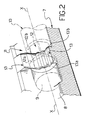
- a retainer means which comprises a groove 12 formed circumferentially around the tang 9 of the mandrel 10 and defining two annular shoulders 12a, 12b facing each other.
- the groove 12 has a polygonal cross-section shape 12c which is hexagonal in the embodiment shown.
- the retainer means 11 further comprises a raised portion 13 in the form of a half-ring concentrical with the rolling axis, being formed in the cradle seat 8 integrally therewith level with the groove 12 and having a compatible length therewith in the axial direction.
- the raised portion 13 defines two opposed ledges 13a, 13b against which the shoulders 12a and 12b abut, respectively.
- the raised portion 13 also has a polygonal cross-section shape 13c but with a number of sides which is twice that of the cross-section shape 12c of the groove 12.
- sprung means mounted on the spindle 7 and effective to secure the tang 9 radially in the cradle seat 8.
- the sprung means 14 comprise an eave 14a arranged to overlie the tang 9 and hold it radially within the seat 8.
- Pusher means 15 are mounted on the hydropneumatic box 3 which act on the sprung means 14 to move the eave 14a from a position where it interferes with the cradle seat 8 to a position where it does not interfere with that seat 8, to accordingly release the tang 9 and allow it to be removed from the spindle 7.
- a so-called mandrel-breaking adapter bush mounted on the spindle 7 and adapted to pull the mandrel 10 out of the pipe 2 on completion of the rolling process.
- the adaptor bush 16 is substantially cradle-shaped and concentrical with the rolling axis, it being accessible from outside both axially and radially through a longitudinal opening bordered by two longitudinal edges 17 and 18 which lie parallel and spaced apart from each other, thereby the mandrel 10 can be fitted or removed in a radial direction.
- the adapter bush 16 extends aligned to the cradle seat 8 in the spindle 7 and opens thereinto.
- the adapter bush 16 is guided for movement along the rolling axis between two ledges 19 and 20 formed on the spindle 7, as will be explained hereinafter.
- a rearward section 21 having a radially raised collar 22 formed integrally on a free end thereof, which fits slidably in a substantially half-ring groove 23 which extends through a wider angle than 180° and is formed in the cradle seat 8 between the raised portion 13 and the forward end 7a of the spindle 7.
- the groove 23 defines two facing walls perpendicular to the rolling axis which constitute said rearward 19 and forward 20 ledges or the collar 22.
- the length of the groove 23 represents, less the thickness of the collar 22, the travel length of the adapter bush 16 relatively to the spindle 7.
- the bush 16 further includes, outside the spindle 7, a forward section 24 which also extends for a predetermined distance along the rolling axis and tapers toward it.
- the rolling mill 1 also comprises a forward interfit means formed on one end of the forward section 24 of the bush 16 and adpated to engage one end of a pipe 2 being rolled.
- the interfit means 29 comprises a plurality of teeth 30, arranged into an annulus around the rolling axis and extending lengthwise thereto; furthermore, each tooth 30 has a back 30a that tapers toward its free end.
- a locking means which comprises a stop 32 affixed to the spindle 7, preferably in interfitting relationship, at the edge 7b, and an insert 33 mounted removably by means of screws 34 on the opposite edge 7c. Both the stop 32 and insert 33 jut over the cradle seat 8 out of the respective edges 7b and 7c of the spindle 7.
- the pusher means 15 is first operated to set the eave 14a of the sprung means 14 in the position not interfering with the cradle seat 8, and then the tang 9 of the mandrel 10 is fitted into that seat 8 with the groove 12 located at the raised portion 13.
- the shoulders 12a and 12b of the groove 12 are caused to abut against their respective ledges 13a and 13b on the raised portion 13, and the mandrel 10 will be retained axially in the cradle seat 8 of the spindle 7.
- the sprung means 14 are released to move the eave 14a to the interfering position, thereby it will move to a location overlying the end of the tang 9 and retain the mandrel 10 radially.
- the polygonal contour 12 of the groove engages with the double polygonal contour of the raised portion 13 and the mandrel 10 is secured on the spindle 7 angularly as well.
- the rotary motion about the rolling axis imparted on the spindle 7 by the aforementioned drive means is likewise transmitted to the mandrel 10.
- the mandrel 10 is in all cases retained axially in the cradle seat 8, even in the event that the tang 9 of the mandrel 10 is fitted into the cradle seat 8 in an angularly inaccurate way, that is even in the event of an improper fit between the polygonal contour of the groove 12 and that of the portion 13.
- the mandrel mounting to the spindle, and accordingly the mandrel replacement is greatly facilitated and can be performed in a very short time, by eliminating any preliminary operations for orienting the mandrel angularly prior to its fitting into the spindle.
- Figures 3 and 4B illustrate another embodiment of the retainer means 11 on a mit-process rolling mill according to the invention, which is advantageously provided for those applications where it is unnecessary to transmit a rotary motion about the rolling axis directly from the spindle 7 to the mandrel 10, or where said motion is transmitted through some additional means, not shown, mounted on the spindle 7 and acting on the mandrel itself.
- the retainer means 11 comprises, similarly to what has been described hereinabove in relation to Figures 1, 2, and 4A, a groove 112 formed circumferentially in the tang 9 and defining two annular shoulders 112A and 112b facing each other, as well as a half-ring raised portion 113 formed on the cradle seat 8 level with the groove 112 and defining two opposed ledges 113a, 113b against which the shoulders abut.
- the cross-sectional shapes, 112c and 113c, of the groove 112 and raised portion 113, respectively, are circular.
- the cylindrical groove 112 will be angularly clear of the raised portion 113, and the mandrel 9 free to turn relatively to the spindle 7, to enhance, therefore, the ready and simple mounting features of the mandrel to a spindle.
- the face teeth 30 on the bush 16 will engage with the trailing end of the pipe 2 and lock the pipe angularly to the bush.
- This is not only advantageous in that initial slip or play can be avoided between the pipe and the mandrel, but is also important where, like in this modified embodiment of the inventive rolling mill, the mandrel is carried on the spindle in a freely rotatable manner.
- the rotary motion imparted on the spindle by the drive means of the hydropneumatic box is transmitted directly to the pipe being rolled.
Landscapes
- Engineering & Computer Science (AREA)
- Mechanical Engineering (AREA)
- Milling Processes (AREA)
- Polishing Bodies And Polishing Tools (AREA)
- Crushing And Grinding (AREA)
Applications Claiming Priority (2)
| Application Number | Priority Date | Filing Date | Title |
|---|---|---|---|
| IT2117888 | 1988-06-30 | ||
| IT21178/88A IT1217979B (it) | 1988-06-30 | 1988-06-30 | Laminatoio a basso di pellegrino |
Publications (2)
| Publication Number | Publication Date |
|---|---|
| EP0348589A2 true EP0348589A2 (de) | 1990-01-03 |
| EP0348589A3 EP0348589A3 (de) | 1990-08-08 |
Family
ID=11177956
Family Applications (1)
| Application Number | Title | Priority Date | Filing Date |
|---|---|---|---|
| EP89100773A Withdrawn EP0348589A3 (de) | 1988-06-30 | 1989-01-18 | Pilgerwalzwerk |
Country Status (2)
| Country | Link |
|---|---|
| EP (1) | EP0348589A3 (de) |
| IT (1) | IT1217979B (de) |
Cited By (3)
| Publication number | Priority date | Publication date | Assignee | Title |
|---|---|---|---|---|
| EP0348595A3 (de) * | 1988-06-30 | 1991-09-25 | INNSE INNOCENTI ENGINEERING S.p.A. | Spindel für Pilgerschrittwalzwerk |
| EP0348596A3 (de) * | 1988-06-30 | 1991-10-02 | INNSE INNOCENTI ENGINEERING S.p.A. | Pilgerschrittwalzwerk zum Warmwalzen von Rohren |
| CN103586283A (zh) * | 2013-11-22 | 2014-02-19 | 四川三洲特种钢管有限公司 | 一种芯棒锁紧机构 |
Family Cites Families (3)
| Publication number | Priority date | Publication date | Assignee | Title |
|---|---|---|---|---|
| DE518506C (de) * | 1929-11-23 | 1931-02-17 | Ewald Roeber | Dornhalter fuer Pilgerschrittwalzwerke, bei dem der Dorn gegen Verdrehung gesichert und gegen axiale Verschiebung verriegelt ist |
| FR2060414A1 (en) * | 1969-09-05 | 1971-06-18 | Innocenti Gle Ind Metal | Mandrel arrangement for seamless tube - reciprocating rolling mill |
| DE2003482A1 (de) * | 1970-01-27 | 1971-08-05 | Kocks Gmbh Friedrich | Dornhalterung |
-
1988
- 1988-06-30 IT IT21178/88A patent/IT1217979B/it active
-
1989
- 1989-01-18 EP EP89100773A patent/EP0348589A3/de not_active Withdrawn
Cited By (4)
| Publication number | Priority date | Publication date | Assignee | Title |
|---|---|---|---|---|
| EP0348595A3 (de) * | 1988-06-30 | 1991-09-25 | INNSE INNOCENTI ENGINEERING S.p.A. | Spindel für Pilgerschrittwalzwerk |
| EP0348596A3 (de) * | 1988-06-30 | 1991-10-02 | INNSE INNOCENTI ENGINEERING S.p.A. | Pilgerschrittwalzwerk zum Warmwalzen von Rohren |
| CN103586283A (zh) * | 2013-11-22 | 2014-02-19 | 四川三洲特种钢管有限公司 | 一种芯棒锁紧机构 |
| CN103586283B (zh) * | 2013-11-22 | 2015-08-19 | 四川三洲特种钢管有限公司 | 一种芯棒锁紧机构 |
Also Published As
| Publication number | Publication date |
|---|---|
| IT8821178A0 (it) | 1988-06-30 |
| IT1217979B (it) | 1990-03-30 |
| EP0348589A3 (de) | 1990-08-08 |
Similar Documents
| Publication | Publication Date | Title |
|---|---|---|
| US5215317A (en) | Keyless chuck | |
| EP0152169B1 (de) | Mehrzweckwerkzeug | |
| US20040139822A1 (en) | Fastener feeding system | |
| GB2360722A (en) | Handheld machine tool with detachable tool holding device | |
| CZ298610B6 (cs) | Stavítkový zámek a kombinace stavítkového zámku aklíce | |
| US4676474A (en) | Ejection coupling for an injection press | |
| JPH10118813A (ja) | キーレスドリルチャック | |
| EP2979790A1 (de) | Drehmeisselhalter für elektrowerkzeug | |
| US4703942A (en) | Hammer drill | |
| US6536316B2 (en) | Pipe beveling and facing tool | |
| EP0348589A2 (de) | Pilgerwalzwerk | |
| US11247254B2 (en) | Adjustable dent removal tool | |
| JP2003518442A (ja) | 複数工具中ぐり棒用補正装置 | |
| US5911804A (en) | Method and apparatus for feeding shaped bar stock | |
| US5391027A (en) | Machine tool system | |
| US10835962B2 (en) | Disengagement mechanism for boring bar apparatus | |
| US4810138A (en) | Tap holder | |
| EP0348596A2 (de) | Pilgerschrittwalzwerk zum Warmwalzen von Rohren | |
| JP4458590B2 (ja) | ガイドブッシュ | |
| EP0047096A2 (de) | Spannfutter | |
| US6125678A (en) | Bending machine to wind a strip or the like into a spiral | |
| EP0719619B1 (de) | Schrauber mit Kupplungsvorrichtung | |
| JPH06304804A (ja) | 切削工具 | |
| JP2826039B2 (ja) | 切削工具 | |
| US10857633B2 (en) | Toolholder with provisions for bit removal |
Legal Events
| Date | Code | Title | Description |
|---|---|---|---|
| PUAI | Public reference made under article 153(3) epc to a published international application that has entered the european phase |
Free format text: ORIGINAL CODE: 0009012 |
|
| AK | Designated contracting states |
Kind code of ref document: A2 Designated state(s): AT BE CH DE ES FR GB GR IT LI LU NL SE |
|
| PUAL | Search report despatched |
Free format text: ORIGINAL CODE: 0009013 |
|
| AK | Designated contracting states |
Kind code of ref document: A3 Designated state(s): AT BE CH DE ES FR GB GR IT LI LU NL SE |
|
| 17P | Request for examination filed |
Effective date: 19901218 |
|
| 17Q | First examination report despatched |
Effective date: 19911213 |
|
| RAP1 | Party data changed (applicant data changed or rights of an application transferred) |
Owner name: INNSE INNOCENTI ENGINEERING S.P.A. |
|
| STAA | Information on the status of an ep patent application or granted ep patent |
Free format text: STATUS: THE APPLICATION IS DEEMED TO BE WITHDRAWN |
|
| 18D | Application deemed to be withdrawn |
Effective date: 19930821 |