EP0348732A2 - Méthode de synchronisation de vitesses rotatives - Google Patents
Méthode de synchronisation de vitesses rotatives Download PDFInfo
- Publication number
- EP0348732A2 EP0348732A2 EP89110755A EP89110755A EP0348732A2 EP 0348732 A2 EP0348732 A2 EP 0348732A2 EP 89110755 A EP89110755 A EP 89110755A EP 89110755 A EP89110755 A EP 89110755A EP 0348732 A2 EP0348732 A2 EP 0348732A2
- Authority
- EP
- European Patent Office
- Prior art keywords
- influencing
- speed
- clutch
- gear
- motor
- Prior art date
- Legal status (The legal status is an assumption and is not a legal conclusion. Google has not performed a legal analysis and makes no representation as to the accuracy of the status listed.)
- Granted
Links
Images
Classifications
-
- B—PERFORMING OPERATIONS; TRANSPORTING
- B60—VEHICLES IN GENERAL
- B60W—CONJOINT CONTROL OF VEHICLE SUB-UNITS OF DIFFERENT TYPE OR DIFFERENT FUNCTION; CONTROL SYSTEMS SPECIALLY ADAPTED FOR HYBRID VEHICLES; ROAD VEHICLE DRIVE CONTROL SYSTEMS FOR PURPOSES NOT RELATED TO THE CONTROL OF A PARTICULAR SUB-UNIT
- B60W10/00—Conjoint control of vehicle sub-units of different type or different function
- B60W10/04—Conjoint control of vehicle sub-units of different type or different function including control of propulsion units
- B60W10/06—Conjoint control of vehicle sub-units of different type or different function including control of propulsion units including control of combustion engines
-
- B—PERFORMING OPERATIONS; TRANSPORTING
- B60—VEHICLES IN GENERAL
- B60W—CONJOINT CONTROL OF VEHICLE SUB-UNITS OF DIFFERENT TYPE OR DIFFERENT FUNCTION; CONTROL SYSTEMS SPECIALLY ADAPTED FOR HYBRID VEHICLES; ROAD VEHICLE DRIVE CONTROL SYSTEMS FOR PURPOSES NOT RELATED TO THE CONTROL OF A PARTICULAR SUB-UNIT
- B60W10/00—Conjoint control of vehicle sub-units of different type or different function
- B60W10/10—Conjoint control of vehicle sub-units of different type or different function including control of change-speed gearings
- B60W10/11—Stepped gearings
-
- B—PERFORMING OPERATIONS; TRANSPORTING
- B60—VEHICLES IN GENERAL
- B60W—CONJOINT CONTROL OF VEHICLE SUB-UNITS OF DIFFERENT TYPE OR DIFFERENT FUNCTION; CONTROL SYSTEMS SPECIALLY ADAPTED FOR HYBRID VEHICLES; ROAD VEHICLE DRIVE CONTROL SYSTEMS FOR PURPOSES NOT RELATED TO THE CONTROL OF A PARTICULAR SUB-UNIT
- B60W30/00—Purposes of road vehicle drive control systems not related to the control of a particular sub-unit, e.g. of systems using conjoint control of vehicle sub-units
- B60W30/18—Propelling the vehicle
-
- F—MECHANICAL ENGINEERING; LIGHTING; HEATING; WEAPONS; BLASTING
- F16—ENGINEERING ELEMENTS AND UNITS; GENERAL MEASURES FOR PRODUCING AND MAINTAINING EFFECTIVE FUNCTIONING OF MACHINES OR INSTALLATIONS; THERMAL INSULATION IN GENERAL
- F16H—GEARING
- F16H3/00—Toothed gearings for conveying rotary motion with variable gear ratio or for reversing rotary motion
- F16H3/02—Toothed gearings for conveying rotary motion with variable gear ratio or for reversing rotary motion without gears having orbital motion
- F16H3/08—Toothed gearings for conveying rotary motion with variable gear ratio or for reversing rotary motion without gears having orbital motion exclusively or essentially with continuously meshing gears, that can be disengaged from their shafts
- F16H3/12—Toothed gearings for conveying rotary motion with variable gear ratio or for reversing rotary motion without gears having orbital motion exclusively or essentially with continuously meshing gears, that can be disengaged from their shafts with means for synchronisation not incorporated in the clutches
-
- F—MECHANICAL ENGINEERING; LIGHTING; HEATING; WEAPONS; BLASTING
- F16—ENGINEERING ELEMENTS AND UNITS; GENERAL MEASURES FOR PRODUCING AND MAINTAINING EFFECTIVE FUNCTIONING OF MACHINES OR INSTALLATIONS; THERMAL INSULATION IN GENERAL
- F16H—GEARING
- F16H61/00—Control functions within control units of change-speed- or reversing-gearings for conveying rotary motion ; Control of exclusively fluid gearing, friction gearing, gearings with endless flexible members or other particular types of gearing
- F16H61/04—Smoothing ratio shift
- F16H61/0403—Synchronisation before shifting
-
- B—PERFORMING OPERATIONS; TRANSPORTING
- B60—VEHICLES IN GENERAL
- B60W—CONJOINT CONTROL OF VEHICLE SUB-UNITS OF DIFFERENT TYPE OR DIFFERENT FUNCTION; CONTROL SYSTEMS SPECIALLY ADAPTED FOR HYBRID VEHICLES; ROAD VEHICLE DRIVE CONTROL SYSTEMS FOR PURPOSES NOT RELATED TO THE CONTROL OF A PARTICULAR SUB-UNIT
- B60W2710/00—Output or target parameters relating to a particular sub-units
- B60W2710/06—Combustion engines, Gas turbines
- B60W2710/0644—Engine speed
-
- B—PERFORMING OPERATIONS; TRANSPORTING
- B60—VEHICLES IN GENERAL
- B60W—CONJOINT CONTROL OF VEHICLE SUB-UNITS OF DIFFERENT TYPE OR DIFFERENT FUNCTION; CONTROL SYSTEMS SPECIALLY ADAPTED FOR HYBRID VEHICLES; ROAD VEHICLE DRIVE CONTROL SYSTEMS FOR PURPOSES NOT RELATED TO THE CONTROL OF A PARTICULAR SUB-UNIT
- B60W30/00—Purposes of road vehicle drive control systems not related to the control of a particular sub-unit, e.g. of systems using conjoint control of vehicle sub-units
- B60W30/18—Propelling the vehicle
- B60W30/19—Improvement of gear change, e.g. by synchronisation or smoothing gear shift
Definitions
- the invention relates to a method for speed synchronization in switching operations in a step change transmission according to the preamble of claim 1 and useful devices for performing this method.
- DE-OS 30 21 489 an embodiment is described for a generic step change transmission which provides for the purpose of speed synchronization the influencing of a transmission input shaft by a motor which can be connected to the transmission input shaft via a clutch.
- load shocks that impair driving comfort and irregularities in the power transmission occur in the drive train during a gear change.
- This method of avoiding load shocks and non-uniformities is only explained in general terms and, particularly in terms of control technology, does not yet show any process steps for functional implementation.
- the invention is therefore based on the object of improving the driving comfort during gear changes for vehicles with generic step change transmissions by sensible further development of the method for speed synchronization.
- load shocks that impair driving comfort during switching operations from one gear gear stage to another gear gear stage are thus avoided by making the positive connection in the other gear gear stage after the speed adjustment of the gear members to be positively connected from the drive side and the output side and a subsequent interruption of the actuation of the speed influencing means First synchronization of the transmission elements with a positive engine speed gradient.
- the closing force of the clutch is influenced in such a way that at the time of establishing the positive connection, only small, predeterminable torques can be transmitted through the clutch.
- the clutch thus enables slippage when the speed of the motor deviates from the speed of the transmission input shaft, which is now positively connected to the output.
- the amount of the transmissible torques is then increased essentially continuously to a predeterminable final amount.
- the engine speed is gently adjusted to the output speed of the new gear stage.
- the specifiable final amount of the transferable torques can be dimensioned so that a permanent residual slip remains. In this way it is possible to improve the comfort of the entire driving operation.
- the closing force of the clutch is controlled in such a way that the motor and the transmission input shaft are just connected before the positive connection is established in the other gear stage.
- the amount of the closing force is selected so that the rotational inertia is just overcome when the transmission input shaft is accelerated or decelerated.
- This amount of closing force is significantly less than the amount of closing force required for the complete transmission of the drive power when the drive train is closed. This ensures that, on the one hand, the transmission input shaft can be influenced by the motor for speed synchronization, and, on the other hand, only small torques can be transmitted by the clutch when establishing the positive connection.
- the engine speed can be increased or decreased by a single speed influencing means.
- a single speed influencing means such a device would be conceivable, for example, in an electric hybrid vehicle in which the motor is connected to an electrical machine via a detachable flywheel. With appropriate control of the electric machine, both an increase and a decrease in the engine speed are possible.
- Another expedient device for carrying out the method according to the invention provides for a two-part design of the speed influencing means.
- the engine speed can be reduced by at least one first speed influencing means and raised by at least a second speed influencing means.
- the first speed influencing means can be, for example, a braking device which acts on the motor and whose brake shoes can be connected to the flywheel mass of the motor in a frictionally locking manner.
- a substantial reduction in wear on the braking device is achieved by an adjustable or controllable influencing device which is assigned to the motor and by means of which the drive torque can be reduced during braking of the motor.
- Such an influencing device can be, for example, a device for influencing the fuel metering, the ignition timing or the fuel-air mixture. Combinations of these influencing options are also conceivable.
- Speed increase means such as throttle valve or fuel injection devices, which are necessary anyway for driving a vehicle, can be used as the second speed influencing means.
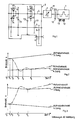
- 1 denotes a motor, which has a clutch 2 Degree of clutch engagement can be influenced, is connected to a gear 3.
- a transmission input shaft 4, a first output shaft 5 and a second output shaft 6 are essentially arranged in the transmission 3.
- the gear input shaft 4 can be positively connected to the first output shaft 5 by means of sliding sleeves 8.1 or 8.2, on which driving teeth are arranged, via gear pairs 7.1 - 7.4 which are constantly in engagement.
- the drive power is transmitted to vehicle wheels (not shown) via the gear pair 9 and the second output shaft 6.
- a flywheel 10 is arranged on the motor 1 and can be acted upon by a braking device 11.
- a speed increase means 12 and a torque influencing device 13 are also assigned to motor 1.
- the diagram shown in FIG. 2 illustrates the qualitative course of the engine speed using a dash-dotted line and the solid course of the qualitative course of the output speeds over time when shifting from third to fourth gear.
- the drive train extending from engine 1 to the vehicle wheels is initially closed.
- the engine torque is first reduced by the torque influencing device 13 - for example a device for adjusting the ignition timing or the fuel quantity - to a predeterminable minimum amount before the time t 1.
- the drive train is then interrupted by disengaging the sliding sleeve 8.1 positively connected to the transmission input shaft 4, so that the idler gear of the gear pair 7.3 rotates freely on the transmission input shaft 4.
- the previously initiated reduction in engine torque initiates a drop in engine speed after the positive locking has been released.
- the braking device 11 acts on the swing firmly connected to the engine 1 mass 10 and with clutch 2 still closed causes an increased drop in the engine speed and thus also the speed of the transmission input shaft 4, up to the time t 3 the driving toothing of the sliding sleeve 8.1 and the idler gear pair 7.4 have the same speeds.
- the application of the flywheel 10 by the braking device 11 is then interrupted at time t3. Due to inertia, the amount of the transmission input shaft speed then sags below the amount of the speed of the idler gear in the gear pair 7.4 and then increases again due to the action of the speed increasing means 12.
- the engine speed can then be adapted gently to the speed of the transmission input shaft 4 by means of an essentially continuous increase in the amount of the transmissible torques within a predeterminable period of time.
- the speed adjustment is finished.
- the speed adjustment can also be dimensioned such that a permanent residual slip remains in the clutch 2 beyond the time t5.
- the influencing of the clutch closing force can take place in the period from t1 to t4. It can be expedient to reduce the closing force of the clutch 2 by means of targeted control or regulation before the establishment of the positive connection within the fourth gear so that the motor 1 and the transmission input shaft 4 are just connected. If it becomes necessary to lower the closing force to an even smaller amount, in this case the clutch opening required for time t4 can be achieved more quickly than with a clutch 2 that was not previously actuated in the opening direction. In this way, the response time of clutch 2 shortened. This can lead to noticeable improvements in shifting comfort.
- a particularly expedient embodiment of a device for carrying out the method according to the invention provides that the driving torque of the motor 1 is reduced by at least one controllable or regulating influencing device (not shown in the drawing) when the motor 1 is acted upon by the braking device 11.
- the wear on the braking device 11 can be reduced by this measure.
- the engine speed is increased by the speed increasing means 12 to a greater extent when the clutch 2 is closed, until the time t3 a first synchronization between the entrainment toothing of the sliding sleeve 8.1 and the idler gear of the gear pair 7.3 is achieved with a positive engine speed gradient.
- the engine speed initially increases slightly due to inertia, and then then drops again.
- the sliding sleeve 8.1 is engaged at the time t 3 and the clutch 2 is controlled in such a way that a gentle adaptation of the engine speed to the speed of the transmission input shaft 4 is again ensured with the least possible tensioning of the drive train at the time t 3.
- the above-described method for avoiding load shocks is of course possible in any switching operation and is not limited to synchronous link-free and four-speed step change transmissions with and without synchronizer links.
Landscapes
- Engineering & Computer Science (AREA)
- Mechanical Engineering (AREA)
- General Engineering & Computer Science (AREA)
- Chemical & Material Sciences (AREA)
- Combustion & Propulsion (AREA)
- Transportation (AREA)
- Automation & Control Theory (AREA)
- Control Of Vehicle Engines Or Engines For Specific Uses (AREA)
- Control Of Transmission Device (AREA)
- Control Of Driving Devices And Active Controlling Of Vehicle (AREA)
- Electrical Control Of Air Or Fuel Supplied To Internal-Combustion Engine (AREA)
- Hydraulic Clutches, Magnetic Clutches, Fluid Clutches, And Fluid Joints (AREA)
- Rotary Pumps (AREA)
Applications Claiming Priority (2)
| Application Number | Priority Date | Filing Date | Title |
|---|---|---|---|
| DE3822218 | 1988-07-01 | ||
| DE3822218 | 1988-07-01 |
Publications (3)
| Publication Number | Publication Date |
|---|---|
| EP0348732A2 true EP0348732A2 (fr) | 1990-01-03 |
| EP0348732A3 EP0348732A3 (en) | 1990-07-04 |
| EP0348732B1 EP0348732B1 (fr) | 1993-09-08 |
Family
ID=6357706
Family Applications (1)
| Application Number | Title | Priority Date | Filing Date |
|---|---|---|---|
| EP89110755A Expired - Lifetime EP0348732B1 (fr) | 1988-07-01 | 1989-06-14 | Méthode de synchronisation de vitesses rotatives |
Country Status (4)
| Country | Link |
|---|---|
| EP (1) | EP0348732B1 (fr) |
| JP (1) | JP2921569B2 (fr) |
| DE (1) | DE58905512D1 (fr) |
| ES (1) | ES2043961T3 (fr) |
Cited By (8)
| Publication number | Priority date | Publication date | Assignee | Title |
|---|---|---|---|---|
| EP0403127B1 (fr) * | 1989-06-12 | 1994-08-31 | Hitachi, Ltd. | Dispositif de commande du changement de vitesse automatique pour véhicules et méthode pour commander |
| EP0943838A1 (fr) * | 1998-03-16 | 1999-09-22 | Eaton Corporation | Système et méthode de changement de vitesse lors du passage à un rapport supérieur assistés par ralentisseur de l'arbre d'entrée |
| EP1310401A1 (fr) * | 2001-11-09 | 2003-05-14 | Renault s.a.s. | Procédé de changement de rapport descendant sur une transmission automatisée |
| EP1283358A3 (fr) * | 2001-08-10 | 2006-03-01 | Kabushiki Kaisha Moric | Méthode et dispositif de commande d'un moteur automobile |
| FR2880592A1 (fr) * | 2005-01-13 | 2006-07-14 | Peugeot Citroen Automobiles Sa | Vehicule equipe de moyens de ralentissement du moteur pour accelerer les passages de rapports de vitesses montants, et methode de passage de rapports associee |
| FR2880593A1 (fr) * | 2005-01-13 | 2006-07-14 | Peugeot Citroen Automobiles Sa | Vehicule equipe de moyens de ralentissement du moteur pour accelerer les passages de rapports de vitesses montants, et methode de passage de rapports associee |
| CN105605164A (zh) * | 2016-02-03 | 2016-05-25 | 安徽好运机械有限公司 | 一种叉车机械变速箱 |
| CN111043300A (zh) * | 2020-01-14 | 2020-04-21 | 中国重汽集团济南动力有限公司 | 一种商用车amt滑套换挡控制方法 |
Families Citing this family (4)
| Publication number | Priority date | Publication date | Assignee | Title |
|---|---|---|---|---|
| DE4005407C2 (de) * | 1989-03-04 | 2001-04-19 | Volkswagen Ag | Drehzahlbeeinflussungsvorrichtung |
| DE10102765A1 (de) * | 2001-01-23 | 2002-07-25 | Volkswagen Ag | Vorrichtung zur Beeinflussung einer Kurbelwellendrehzahl einer Brennkraftmaschine |
| DE10332668B4 (de) * | 2003-07-18 | 2007-04-26 | Adam Opel Ag | Schaltbares Antriebssystem, Komponenten und Betriebsverfahren dafür |
| CN103158554B (zh) * | 2011-12-14 | 2015-07-08 | 北汽福田汽车股份有限公司 | 带amt变速箱的电动汽车的换挡控制方法 |
Family Cites Families (9)
| Publication number | Priority date | Publication date | Assignee | Title |
|---|---|---|---|---|
| GB1310515A (en) * | 1969-07-07 | 1973-03-21 | Cav Ltd | Transmission systems |
| DE2217482A1 (de) * | 1972-04-12 | 1973-11-08 | Polly Johann | Getriebe, insbesondere fuer kraftfahrzeuge |
| AU525952B2 (en) * | 1978-01-24 | 1982-12-09 | Lahive, John A. | Mechanical automatic transmission |
| DE3021489A1 (de) * | 1980-06-07 | 1981-12-24 | Volkswagenwerk Ag, 3180 Wolfsburg | Einrichtung zum synchronisierten schalten eines kraftfahrzeug-schaltgetriebes |
| GB2100384B (en) * | 1981-06-02 | 1985-02-27 | Automotive Products Plc | Rotary transmission |
| JPS60240533A (ja) * | 1984-05-16 | 1985-11-29 | Toyota Motor Corp | 車両用自動変速装置 |
| DE3420126A1 (de) * | 1984-05-30 | 1985-12-05 | Robert Bosch Gmbh, 7000 Stuttgart | Verfahren zum steuern des schaltablaufs bei einem automatischen stufengetriebe beim rueckschalten |
| FR2609138B1 (fr) * | 1986-12-26 | 1989-11-10 | Renault | Procede et dispositif de commande automatique de changement de rapport de transmission pour un ensemble embrayage boite de vitesses |
| GB8810365D0 (en) * | 1988-04-30 | 1988-06-08 | Automotive Prod Plc | Power line to drive vehicle |
-
1989
- 1989-06-14 DE DE89110755T patent/DE58905512D1/de not_active Expired - Fee Related
- 1989-06-14 EP EP89110755A patent/EP0348732B1/fr not_active Expired - Lifetime
- 1989-06-14 ES ES89110755T patent/ES2043961T3/es not_active Expired - Lifetime
- 1989-06-30 JP JP1167193A patent/JP2921569B2/ja not_active Expired - Lifetime
Cited By (11)
| Publication number | Priority date | Publication date | Assignee | Title |
|---|---|---|---|---|
| EP0403127B1 (fr) * | 1989-06-12 | 1994-08-31 | Hitachi, Ltd. | Dispositif de commande du changement de vitesse automatique pour véhicules et méthode pour commander |
| EP0943838A1 (fr) * | 1998-03-16 | 1999-09-22 | Eaton Corporation | Système et méthode de changement de vitesse lors du passage à un rapport supérieur assistés par ralentisseur de l'arbre d'entrée |
| US6017291A (en) * | 1998-03-16 | 2000-01-25 | Eaton Corporation | Control system/method for input shaft retarder-assisted upshifts |
| EP1283358A3 (fr) * | 2001-08-10 | 2006-03-01 | Kabushiki Kaisha Moric | Méthode et dispositif de commande d'un moteur automobile |
| EP1310401A1 (fr) * | 2001-11-09 | 2003-05-14 | Renault s.a.s. | Procédé de changement de rapport descendant sur une transmission automatisée |
| FR2832198A1 (fr) * | 2001-11-09 | 2003-05-16 | Renault | Procede de changement de rapport descendant sur une transmission automatisee |
| FR2880592A1 (fr) * | 2005-01-13 | 2006-07-14 | Peugeot Citroen Automobiles Sa | Vehicule equipe de moyens de ralentissement du moteur pour accelerer les passages de rapports de vitesses montants, et methode de passage de rapports associee |
| FR2880593A1 (fr) * | 2005-01-13 | 2006-07-14 | Peugeot Citroen Automobiles Sa | Vehicule equipe de moyens de ralentissement du moteur pour accelerer les passages de rapports de vitesses montants, et methode de passage de rapports associee |
| CN105605164A (zh) * | 2016-02-03 | 2016-05-25 | 安徽好运机械有限公司 | 一种叉车机械变速箱 |
| CN105605164B (zh) * | 2016-02-03 | 2020-03-31 | 安徽天乐传动技术发展有限公司 | 一种叉车机械变速箱 |
| CN111043300A (zh) * | 2020-01-14 | 2020-04-21 | 中国重汽集团济南动力有限公司 | 一种商用车amt滑套换挡控制方法 |
Also Published As
| Publication number | Publication date |
|---|---|
| DE58905512D1 (de) | 1993-10-14 |
| EP0348732B1 (fr) | 1993-09-08 |
| EP0348732A3 (en) | 1990-07-04 |
| JP2921569B2 (ja) | 1999-07-19 |
| JPH0266370A (ja) | 1990-03-06 |
| ES2043961T3 (es) | 1994-01-01 |
Similar Documents
| Publication | Publication Date | Title |
|---|---|---|
| EP0825058B1 (fr) | Procédé de changement de vitesses d'une boíte de vitesses à double embrayage et transmission à double embrayage avec dispositif de synchronisation | |
| EP0827861B1 (fr) | Procédé de changement de vitesses d'une boîte de vitesses à double embrayage et transmission à double embrayage | |
| DE19717042C2 (de) | Verfahren zum Schalten eines synchronisiergliederfreien Zahnräderwechselgetriebes | |
| EP0517705B1 (fr) | Procede de changement de vitesse dans une transmission a variation discontinue de la vitesse | |
| EP0088150B1 (fr) | Agencement d'une transmission mécanique à changement de vitesse sous charge | |
| DE69905485T2 (de) | Verfahren zur steuerung des motordrehmoments während eines schaltvorganges | |
| DE102005016117A1 (de) | Verfahren zum Ansteuern eines Schaltvorganges bei einem Getriebe eines Hybridfahrzeuges | |
| EP0348732B1 (fr) | Méthode de synchronisation de vitesses rotatives | |
| EP0367020B1 (fr) | Procédé de changement de rapport d'une boîte de vitesse | |
| DE10135327A1 (de) | Automatisiertes Zahnräderwechselgetriebe und Verfahren zum Gangwechsel bei einem solchen | |
| EP3368389A1 (fr) | Procédé et dispositif de commande destinés à faire fonctionner un véhicule à moteur | |
| DE102016209006A1 (de) | Verfahren zum Betrieb eines Antriebsstrangs eines Hybridfahrzeugs und Antriebsstrang eines Hybridfahrzeugs | |
| DE19751456B4 (de) | Verfahren zum Schalten eines Doppelkupplungsgetriebes | |
| EP2718593B1 (fr) | Procédé pour faire fonctionner un dispositif d'entraînement ainsi que dispositif pour le fonctionnement du dispositif d'entraînement | |
| EP0992715B1 (fr) | Boíte de vitesses à rapports étagés ainsi qu'une procédure pour le dégagement d'un rapport d'une telle boíte de vitesses | |
| DE102014219099B4 (de) | Verfahren zur Schaltsteuerung eines automatisierten Schaltgetriebes in einem elektromotorisch angetriebenen Fahrzeug | |
| DE19934997A1 (de) | Verfahren zur Steuerung eines Schaltvorgangs eines automatisierten Doppelkupplungsgetriebes | |
| EP1753982A1 (fr) | Procede de commande d'une transmission automatique | |
| EP3510295B1 (fr) | Procédé permettant de synchroniser deux éléments d'entraînement d'une chaîne cinématique d'un véhicule automobile, et chaîne cinématique pour un véhicule automobile | |
| DE102016224930B4 (de) | Verfahren zur Steuerung und/oder Regelung eines Antriebsstranges, insbesondere eines Hybrid-Antriebsstranges eines Kraftfahrzeugs | |
| DE60103831T2 (de) | Methode zum Einstellen des Antriebmomentes während eines Schaltvorganges | |
| DE102013216144A1 (de) | Verfahren zur Schaltsteuerung eines Fahrzeuggetriebes | |
| DE3334710C2 (fr) | ||
| DE19806149C1 (de) | Zahnräderwechselgetriebe | |
| DE102024206486B3 (de) | Verfahren zum Steuern einer Antriebsvorrichtung bei einer Lastschaltung |
Legal Events
| Date | Code | Title | Description |
|---|---|---|---|
| PUAI | Public reference made under article 153(3) epc to a published international application that has entered the european phase |
Free format text: ORIGINAL CODE: 0009012 |
|
| AK | Designated contracting states |
Kind code of ref document: A2 Designated state(s): DE ES FR IT |
|
| PUAL | Search report despatched |
Free format text: ORIGINAL CODE: 0009013 |
|
| AK | Designated contracting states |
Kind code of ref document: A3 Designated state(s): DE ES FR IT |
|
| 17P | Request for examination filed |
Effective date: 19900719 |
|
| 17Q | First examination report despatched |
Effective date: 19920629 |
|
| GRAA | (expected) grant |
Free format text: ORIGINAL CODE: 0009210 |
|
| AK | Designated contracting states |
Kind code of ref document: B1 Designated state(s): DE ES FR IT |
|
| REF | Corresponds to: |
Ref document number: 58905512 Country of ref document: DE Date of ref document: 19931014 |
|
| ET | Fr: translation filed | ||
| ITF | It: translation for a ep patent filed | ||
| REG | Reference to a national code |
Ref country code: ES Ref legal event code: FG2A Ref document number: 2043961 Country of ref document: ES Kind code of ref document: T3 |
|
| PGFP | Annual fee paid to national office [announced via postgrant information from national office to epo] |
Ref country code: LU Payment date: 19940630 Year of fee payment: 6 |
|
| PLBE | No opposition filed within time limit |
Free format text: ORIGINAL CODE: 0009261 |
|
| STAA | Information on the status of an ep patent application or granted ep patent |
Free format text: STATUS: NO OPPOSITION FILED WITHIN TIME LIMIT |
|
| EPTA | Lu: last paid annual fee | ||
| 26N | No opposition filed | ||
| PGFP | Annual fee paid to national office [announced via postgrant information from national office to epo] |
Ref country code: ES Payment date: 20000619 Year of fee payment: 12 |
|
| PGFP | Annual fee paid to national office [announced via postgrant information from national office to epo] |
Ref country code: FR Payment date: 20000621 Year of fee payment: 12 |
|
| PG25 | Lapsed in a contracting state [announced via postgrant information from national office to epo] |
Ref country code: ES Free format text: LAPSE BECAUSE OF NON-PAYMENT OF DUE FEES Effective date: 20010615 |
|
| PG25 | Lapsed in a contracting state [announced via postgrant information from national office to epo] |
Ref country code: FR Free format text: LAPSE BECAUSE OF NON-PAYMENT OF DUE FEES Effective date: 20020228 |
|
| REG | Reference to a national code |
Ref country code: ES Ref legal event code: FD2A Effective date: 20030203 |
|
| PG25 | Lapsed in a contracting state [announced via postgrant information from national office to epo] |
Ref country code: IT Free format text: LAPSE BECAUSE OF NON-PAYMENT OF DUE FEES;WARNING: LAPSES OF ITALIAN PATENTS WITH EFFECTIVE DATE BEFORE 2007 MAY HAVE OCCURRED AT ANY TIME BEFORE 2007. THE CORRECT EFFECTIVE DATE MAY BE DIFFERENT FROM THE ONE RECORDED. Effective date: 20050614 |
|
| PGFP | Annual fee paid to national office [announced via postgrant information from national office to epo] |
Ref country code: DE Payment date: 20070630 Year of fee payment: 19 |
|
| PG25 | Lapsed in a contracting state [announced via postgrant information from national office to epo] |
Ref country code: DE Free format text: LAPSE BECAUSE OF NON-PAYMENT OF DUE FEES Effective date: 20090101 |