EP0348774A2 - Système constitué d'au moins deux appareils électroniques de divertissement à télécommande - Google Patents
Système constitué d'au moins deux appareils électroniques de divertissement à télécommande Download PDFInfo
- Publication number
- EP0348774A2 EP0348774A2 EP89111064A EP89111064A EP0348774A2 EP 0348774 A2 EP0348774 A2 EP 0348774A2 EP 89111064 A EP89111064 A EP 89111064A EP 89111064 A EP89111064 A EP 89111064A EP 0348774 A2 EP0348774 A2 EP 0348774A2
- Authority
- EP
- European Patent Office
- Prior art keywords
- remote control
- memory
- additional
- transmitter
- command code
- Prior art date
- Legal status (The legal status is an assumption and is not a legal conclusion. Google has not performed a legal analysis and makes no representation as to the accuracy of the status listed.)
- Withdrawn
Links
Images


Classifications
-
- G—PHYSICS
- G11—INFORMATION STORAGE
- G11B—INFORMATION STORAGE BASED ON RELATIVE MOVEMENT BETWEEN RECORD CARRIER AND TRANSDUCER
- G11B31/00—Arrangements for the associated working of recording or reproducing apparatus with related apparatus
- G11B31/006—Arrangements for the associated working of recording or reproducing apparatus with related apparatus with video camera or receiver
-
- G—PHYSICS
- G11—INFORMATION STORAGE
- G11B—INFORMATION STORAGE BASED ON RELATIVE MOVEMENT BETWEEN RECORD CARRIER AND TRANSDUCER
- G11B15/00—Driving, starting or stopping record carriers of filamentary or web form; Driving both such record carriers and heads; Guiding such record carriers or containers therefor; Control thereof; Control of operating function
- G11B15/02—Control of operating function, e.g. switching from recording to reproducing
- G11B15/023—Control of operating function, e.g. switching from recording to reproducing remotely controlled
-
- H—ELECTRICITY
- H04—ELECTRIC COMMUNICATION TECHNIQUE
- H04B—TRANSMISSION
- H04B1/00—Details of transmission systems, not covered by a single one of groups H04B3/00 - H04B13/00; Details of transmission systems not characterised by the medium used for transmission
- H04B1/06—Receivers
- H04B1/16—Circuits
- H04B1/20—Circuits for coupling gramophone pick-up, recorder output, or microphone to receiver
- H04B1/205—Circuits for coupling gramophone pick-up, recorder output, or microphone to receiver with control bus for exchanging commands between units
Definitions
- the invention relates to a device system according to the preamble of claim 1.
- the invention is therefore based on the object of creating a possibility with which at least two electrical devices of entertainment electronics of different remote control transmission systems which are combined in a device system and can be remote-controlled next to one another can nevertheless be operated side by side with a single remote control transmitter.
- This object is achieved according to the invention by the features specified in the characterizing part of claim 1.
- the most common remote control transmission systems are programmed into a device system according to the invention.
- a device system formed from a number of commercially available consumer electronics devices is thus set up in a simple manner for the remote control of these devices with only one remote control, even when these devices are used different, incompatible remote control transmission systems work.
- the setting of the device system for the remote control of certain commercial devices located in the household of a user and assembled into a device system can also be carried out in a simple manner for the less technically experienced user.
- the additional circuits and memories required for the adjustable or programmable remote control circuit are arranged exclusively in the remote control transmitter.
- the device for remote control of devices with different remote control transmission systems is thus only arranged in the remote control transmitter.
- all commercially available consumer electronics devices, whose remote control transmission system and remote control code are stored in the remote control transmitter can be operated remotely with the one remote control transmitter of the device system as soon as the corresponding remote control transmission system and the corresponding remote control code are also activated in the remote control transmitter.
- these additional circuits are in a further advantageous embodiment of the invention housed in one of the devices of the entertainment electronics of the device system.
- the remote control transmitter of the device system is then assigned to this device.
- this device evaluates the remote control signals received by it itself or converts them into commands of the preset remote control transmission system and sends them out in a wired or wireless manner to the other devices in the entertainment electronics of the device system.
- the other devices of the device system are also commercially available devices of entertainment electronics. However, they do not contain any additional devices for the remote control of other devices of the device system.
- the selection of the devices of such a device system to be operated remotely takes place either via different key groups of the remote control transmitter or via special operating elements additionally arranged on the remote control transmitter for selecting the device of the entertainment electronics to be operated remotely.
- the setting elements for setting the desired remote control transmission system are designed so that this setting must be carried out in a simple manner, but consciously and specifically and cannot be changed accidentally by incorrect operation of the remote control transmitter.
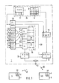
- the two devices 5 and 7 of the entertainment electronics are shown as device blocks and an associated remote control transmitter 1 as a block diagram.
- the devices 5 and 7 form with the remote control transmitter 1, a device system that can be operated remotely by the remote control transmitter 1.
- the remote control transmitter 1 contains two button groups 2 and 3 on a control panel 34.
- the first button group 2 comprises operating elements 4 for remote control of the first device 5 of the entertainment electronics, in the illustrated embodiment of a video recorder.
- the second button group 3 includes controls 6 for operating the second remotely controllable device 7 of entertainment electronics, in illustrated embodiment of a television receiver from a manufacturer other than the manufacturer of the video recorder 5. Accordingly, the remote control receiver parts 8 and 9 of the two devices 5 and 6 are components of different remote control systems.
- a system data memory and command code memory 10 is connected to the first button group 2, which contains both the command code and the system data of the remote control transmission system S0 of the video recorder 5 assigned to the remote control transmitter and the associated command code for an operating element 4 operated in the first button group 2 to a sequence control circuit 11 transmits and starts the program flow of this control circuit. From this, the sequence control circuit 11 generates the remote control signals 38 of the remote control transmission system S0, which is installed in the remote control receiving part 8 of the video recorder 5, and transmits these remote control signals in accordance with this remote control transmission system via a transmitter element 12 to a receiving element 35 of the two remotely controllable devices 5 and 7 of the entertainment electronics.
- the key elements 6 of the second key group 3 of the remote control transmitter 1 are connected to the inputs of a number of additional command code converters 13 to 18 and a transmission circuit 19.
- Each of these additional command code converters 13 to 18 contains a set of command codes BC2.2 to BC6 assigned to the operating elements 6 of the second key group 3.
- the individual command code converters 13 to 18 are assigned to additional system data memories 21 to 24.
- One of these system data memories contains the system data and the program sequence data of a specific remote control transmission system S1 to S4, which are required for the control of a second sequence control circuit 25 so that the second sequence control circuit 25 can form the remote control signals of the relevant remote control transmission system therefrom.
- the selection of which of the additional system data memories S1 to S4 and, if appropriate, which additional command code converter associated with the selected additional system data memory should cooperate with the second sequence control circuit 25 in a remote control circuit is made by a solder bridge 26 between the selection contacts 27 of a solder bridge arrangement 28.
- the additional system data memory 23 for the remote control transmission system S3 and the additional command code converter 13 with the command code set BC2.2 are activated with the second sequence control circuit 25 to form a remote control circuit.
- the transmission circuit 19 in the remote control transmitter is activated with a solder bridge in the solder bridge arrangement 28.
- the key signals of the operating elements operated in the second key group 3 are transferred circuit 19 transmitted directly to the system data memory and command code memory 10 for the remote control transmission system S0 of the video recorder 5.
- the program sequence in the sequence control circuit 11 is set via a connection 29 such that the remote control signals generated by the sequence control circuit 11 contain an address signal which only switches the remote control receiver part 9 of the television set 7 into effect.
- S1, S3 are assigned more than one additional command code converter. This is the case when consumer electronics devices work with the same remote control transmission system, but which, due to the different makes of the devices or the further development of the devices, contain tables with different command codes for the same commands.
- the solder bridge assembly 28 is covered and attached, for example, in the remote control transmitter 1 via the battery compartment. It serves to select the corresponding remote control circuit for the second key group 3 and to mark it with a solder bridge 26 and thus to set it.
- the additional system data memory 23 is marked with the command code converter 13 by the solder bridge 26, so that these two circuits form a remote control circuit with the second sequence control circuit 25, which generates the selected remote control signals of the command code BC2.2 in the desired remote control transmission system S3. Only one solder bridge may ever be made in the solder bridge arrangement 28.
- a slide switch can be used instead of a solder bridge arrangement.
- the remote control transmitter 1 shown in FIG. 2 differs from the remote control transmitter 1 shown in FIG. 1 essentially in that it contains only one sequence control circuit 25, that it also contains a system data memory 20 which is separate from the command code memory 10 and in which the program sequence data and system data of the remote control transmission system S0 of the video recorder 5 are stored, and that it contains, as a marking arrangement, an allocation memory 30 which contains an allocation memory location (31.1 to 31.7) for each marking location.
- the additional system data memory 23 assigned to this assignment memory location and the additional command code converter 13 assigned to this assignment memory location are activated to a remote control circuit, so that when one of the operating elements 6 or 4 of the key groups 2 or 3 is activated, the sequence control circuit 25, the marked command code converter 13 and the marked system data memory 23 remote control circuit formed is set in motion and the sequence control circuit 25 forms the corresponding remote control signal from the data of this remote control circuit.
- the operating elements TV0 and L or the second key group are actuated simultaneously for programming the allocator memory 30 and during the actuation of these two operating elements, the assigned memory location 31.5 is set by actuating a specific operating element of the first key group.
- the assignor memory 30 is a non-volatile memory, the programmed assignment of which is retained even when the battery on the remote control transmitter is changed and is only changed according to the program by a new setting.
- the two remote-controlled devices 5 and 7 shown in FIG. 2 are connected to one another by a cable 32, via which, when the video broadcast recorded on a video cassette 33 is played back, the video signals reach the television 7, on the screen 34 of which the video broadcast recorded on the video cassette 33 is reproduced becomes.
- the key group 3 provided for operating the television 7 contains only the keys which are absolutely necessary for operating the television 7 in cooperation with the video recorder 5.
- the control panel 34 of the remote control transmitter 1 remains clear for the user of the remote control transmitter.
- the command code memory 10 and the additional command code converters 13 to 18, the system data memory 20, the additional system data memory 21 to 24, the sequence control circuit 25 and the assignor memory 30 are components of a microprocessor in a particularly advantageous embodiment of the remote control transmitter shown in FIG. The same applies for the modules 13 to 25 of the exemplary embodiment of a remote control transmitter 1 shown in FIG. 1.
- the second sequence control circuit 25 and the additional system data memories and the additional command code converters are not in the remote control transmitter, but arranged in one of the devices of the entertainment electronics of the device system. This has the advantage that a larger amount of additional system data memories and additional command code converters can be accommodated.
- the second sequence control circuit 25, the additional command code converters 13 to 18 and the additional system data memories 21 to 24 and the assignment memory 30 are arranged in the video recorder 5.
- the associated remote control transmitter 1 contains a first keypad 2 with the operating elements 4 for remote control of the video recorder 5 and a second keypad 3 for operating the television set 7 in certain operating states required in connection with the video recorder.
- the remote control commands called up from the second keypad 3 receive an identification signal KS which is generated in the remote control circuit of the remote control transmitter 1 formed from the command code memory and system data memory 10 and the sequence control circuit 11.
- the remote control receiving part 8 of the video recorder 5 which separates the remote control commands from the wirelessly transmitted remote control signal, transmits the remote control commands called up with the first keypad 2 to a function control circuit 36 of the video recorder 5 for setting the corresponding video recorder functions.
- this remote control command reaches the signal input of the function control circuit 40 of the television 7 via a signal line 41 of a cable (not shown in more detail), which is thereby controlled into the desired operating state.
- the embodiment shown in Figure 4 of a device system containing two devices 5 and 7 of the entertainment electronics differs from the embodiment of a device system shown in Figure 3 essentially only in that the sequence control circuit 25 of the remote control circuit of the video recorder also formed from the marked command code converter and the marked system data memory 5 generates a remote control signal 42 at its output, the is wirelessly transmitted to the remote control receiving part 9 of the television 7.
- This remote control receiving part 9 transmits the remote control commands received with the remote control signal to the function control circuit 40 of the television 7 for setting the corresponding operating procedures or operating values of the television 7.
- the wireless transmission of the remote control signals between the two devices 5 and 7 of the entertainment electronics takes place either via a transmission element 43 which is mounted directly in the housing wall 44 of the video recorder 5 or via a transmission element 45 of a transmission device 46 which is connected to the video recorder 5 via a cable 47.
- the transmitting element 45 can be set most easily into the most favorable transmission position to the other device or to the other devices of the device system.
- the remote control transmitter 1 contains only a button group 2, or in an alternative embodiment of a remote control transmitter 1 'shown by an angular offset of a main axis 48 of the remote control transmitter 1' of a specific normal direction controlled command generator 49.
- the assignment of the key group 2 or the command generator 49 to the individual remote-controlled devices of the device system is determined by the user by actuating certain selection control elements 50.
- the actuated element of the selection controls 50 triggered in the command code memory and system data memory 10 of the remote control transmitter 1 or 1 'a corresponding identification signal KS1, KS2 or KS3, which identifies the device of the device system that just is operated remotely and is transmitted with the remote control command with the remote control signal 38 generated in the remote control transmitter to the remote control receiving part 8 of the video recorder 5 for further processing.
Landscapes
- Engineering & Computer Science (AREA)
- Multimedia (AREA)
- Computer Networks & Wireless Communication (AREA)
- Signal Processing (AREA)
- Selective Calling Equipment (AREA)
- Details Of Television Systems (AREA)
Applications Claiming Priority (4)
| Application Number | Priority Date | Filing Date | Title |
|---|---|---|---|
| DE3821751 | 1988-06-28 | ||
| DE3821751 | 1988-06-28 | ||
| DE3918578 | 1989-06-07 | ||
| DE19893918578 DE3918578A1 (de) | 1988-06-28 | 1989-06-07 | Geraetesystem aus wenigstens zwei drahtlos fernbedienbaren geraeten der unterhaltungselektronik |
Publications (2)
| Publication Number | Publication Date |
|---|---|
| EP0348774A2 true EP0348774A2 (fr) | 1990-01-03 |
| EP0348774A3 EP0348774A3 (fr) | 1991-05-08 |
Family
ID=25869524
Family Applications (1)
| Application Number | Title | Priority Date | Filing Date |
|---|---|---|---|
| EP19890111064 Withdrawn EP0348774A3 (fr) | 1988-06-28 | 1989-06-19 | Système constitué d'au moins deux appareils électroniques de divertissement à télécommande |
Country Status (3)
| Country | Link |
|---|---|
| EP (1) | EP0348774A3 (fr) |
| JP (1) | JPH0297195A (fr) |
| DE (1) | DE3918578A1 (fr) |
Families Citing this family (1)
| Publication number | Priority date | Publication date | Assignee | Title |
|---|---|---|---|---|
| JP3193176B2 (ja) * | 1993-03-05 | 2001-07-30 | パイオニア株式会社 | 双方向リモートコントロールシステム |
Family Cites Families (9)
| Publication number | Priority date | Publication date | Assignee | Title |
|---|---|---|---|---|
| JPS59171397A (ja) * | 1983-03-18 | 1984-09-27 | Sony Corp | 遠隔操作装置 |
| JPS59171398A (ja) * | 1983-03-18 | 1984-09-27 | Sony Corp | 遠隔操作指令装置 |
| US4623887A (en) * | 1984-05-15 | 1986-11-18 | General Electric Company | Reconfigurable remote control |
| US4774511A (en) * | 1985-05-30 | 1988-09-27 | Nap Consumer Electronics Corp. | Universal remote control unit |
| JPH06101867B2 (ja) * | 1985-11-14 | 1994-12-12 | ソニー株式会社 | テレビジョン受像機 |
| JPH07105895B2 (ja) * | 1986-06-02 | 1995-11-13 | ソニー株式会社 | 電子機器 |
| JPS632499A (ja) * | 1986-06-20 | 1988-01-07 | Mitsubishi Electric Corp | 万能遠隔操作送信機 |
| JPS6314576A (ja) * | 1986-07-07 | 1988-01-21 | Nec Corp | リモ−トコントロ−ル装置 |
| JPH0710091B2 (ja) * | 1986-10-24 | 1995-02-01 | ソニー株式会社 | 電子機器 |
-
1989
- 1989-06-07 DE DE19893918578 patent/DE3918578A1/de not_active Withdrawn
- 1989-06-19 EP EP19890111064 patent/EP0348774A3/fr not_active Withdrawn
- 1989-06-28 JP JP16649189A patent/JPH0297195A/ja active Granted
Also Published As
| Publication number | Publication date |
|---|---|
| JPH0297195A (ja) | 1990-04-09 |
| EP0348774A3 (fr) | 1991-05-08 |
| DE3918578A1 (de) | 1990-01-11 |
| JPH0557800B2 (fr) | 1993-08-24 |
Similar Documents
| Publication | Publication Date | Title |
|---|---|---|
| EP0348726A2 (fr) | Dispositif de commande à distance | |
| EP0780990B1 (fr) | Procédé et dispositif de commande à distance d'equipement électronique | |
| DE69837653T2 (de) | Automatische konfigurationseinrichtung für universale fernsteuerung | |
| DE69027244T2 (de) | Fernsteuerung für elektronische Apparate | |
| DE3305090C3 (de) | Einrichtung zum Fernsteuern eines Video-Magnetbandrecorders und eines mit diesem verbundenen Fernsehempfängers | |
| EP0354459B1 (fr) | Récepteur de télévision | |
| DE3815560C2 (fr) | ||
| DE69423615T2 (de) | System und methode zur automatischen aufzeichnung von fernsehprogrammen in fernsehsystemen mit tunern ausserhalb der videorekorder | |
| EP0112589B1 (fr) | Dispositif pour la commande programmée d'un récepteur radiophonique ou/et de télévision | |
| EP0002434A1 (fr) | Dispositif de télécommande pour la commande, la mise en service et la commutation de fonctions et de grandeurs de réglage dans des équipements de télécommunication | |
| DE4317313A1 (de) | Vorrichtung und Verfahren zum Steuern eines Fernsehempfängers | |
| DE3921847A1 (de) | Einrichtung zur programmwahl mittels teletexttabelle | |
| DE9309894U1 (de) | Universelle Fernbedienungsanordnung | |
| EP0002435A1 (fr) | Dispositif de télécommande pour la commande, la mise en service et la commutation de fonctions et de paramètres variables et fixes dans des équipements de télécommunication | |
| DE3820613A1 (de) | Digitales signaluebertragungssystem | |
| DE4440861C2 (de) | Videovorrichtung mit einer Spielfunktion | |
| EP0413225B1 (fr) | Serrure à combinaison électrique commandée en temps pour la protection d'un appareil contre une utilisation non autorisée | |
| DE69418457T2 (de) | Kombination von aufzeichnungsvorrichtung und quellenauswahlvorrichtung | |
| DE2744057A1 (de) | Fernsteuerung zum steuern, ein- und umschalten von variablen und festen geraetefunktionen und funktionsgroessen in nachrichtentechnischen geraeten | |
| EP0489093B1 (fr) | Systeme de telecommande | |
| DE69837172T2 (de) | Fernsteuerungs- und Signalübertragungseinrichtung | |
| EP0447934B1 (fr) | Procédé pour l'introduction de données techniques de commutation relatives à l'exploitation et aux abonnés dans des centraux de commutation et/ou dans des terminaux de communication programmables | |
| EP0348774A2 (fr) | Système constitué d'au moins deux appareils électroniques de divertissement à télécommande | |
| EP0881115B1 (fr) | Dispositif de réglage d'un siège et autoradio. | |
| DE4021482C2 (de) | Bedienvorrichtung für ein Audiogerät mit mehreren Tonsignalquellen |
Legal Events
| Date | Code | Title | Description |
|---|---|---|---|
| PUAI | Public reference made under article 153(3) epc to a published international application that has entered the european phase |
Free format text: ORIGINAL CODE: 0009012 |
|
| AK | Designated contracting states |
Kind code of ref document: A2 Designated state(s): AT BE DE ES FR GB IT LU NL |
|
| PUAL | Search report despatched |
Free format text: ORIGINAL CODE: 0009013 |
|
| RHK1 | Main classification (correction) |
Ipc: H04B 1/20 |
|
| AK | Designated contracting states |
Kind code of ref document: A3 Designated state(s): AT BE DE ES FR GB IT LU NL |
|
| STAA | Information on the status of an ep patent application or granted ep patent |
Free format text: STATUS: THE APPLICATION IS DEEMED TO BE WITHDRAWN |
|
| 18D | Application deemed to be withdrawn |
Effective date: 19911109 |