EP0348846A2 - Rotor balancé d'un ventilateur ainsi que méthode et appareil pour réaliser l'équilibrage - Google Patents
Rotor balancé d'un ventilateur ainsi que méthode et appareil pour réaliser l'équilibrage Download PDFInfo
- Publication number
- EP0348846A2 EP0348846A2 EP89111501A EP89111501A EP0348846A2 EP 0348846 A2 EP0348846 A2 EP 0348846A2 EP 89111501 A EP89111501 A EP 89111501A EP 89111501 A EP89111501 A EP 89111501A EP 0348846 A2 EP0348846 A2 EP 0348846A2
- Authority
- EP
- European Patent Office
- Prior art keywords
- fan wheel
- fan
- compensating elements
- elements
- balanced
- Prior art date
- Legal status (The legal status is an assumption and is not a legal conclusion. Google has not performed a legal analysis and makes no representation as to the accuracy of the status listed.)
- Granted
Links
Images
Classifications
-
- F—MECHANICAL ENGINEERING; LIGHTING; HEATING; WEAPONS; BLASTING
- F16—ENGINEERING ELEMENTS AND UNITS; GENERAL MEASURES FOR PRODUCING AND MAINTAINING EFFECTIVE FUNCTIONING OF MACHINES OR INSTALLATIONS; THERMAL INSULATION IN GENERAL
- F16F—SPRINGS; SHOCK-ABSORBERS; MEANS FOR DAMPING VIBRATION
- F16F15/00—Suppression of vibrations in systems; Means or arrangements for avoiding or reducing out-of-balance forces, e.g. due to motion
- F16F15/32—Correcting- or balancing-weights or equivalent means for balancing rotating bodies, e.g. vehicle wheels
-
- F—MECHANICAL ENGINEERING; LIGHTING; HEATING; WEAPONS; BLASTING
- F04—POSITIVE - DISPLACEMENT MACHINES FOR LIQUIDS; PUMPS FOR LIQUIDS OR ELASTIC FLUIDS
- F04D—NON-POSITIVE-DISPLACEMENT PUMPS
- F04D29/00—Details, component parts, or accessories
- F04D29/26—Rotors specially for elastic fluids
- F04D29/28—Rotors specially for elastic fluids for centrifugal or helico-centrifugal pumps for radial-flow or helico-centrifugal pumps
- F04D29/281—Rotors specially for elastic fluids for centrifugal or helico-centrifugal pumps for radial-flow or helico-centrifugal pumps for fans or blowers
- F04D29/282—Rotors specially for elastic fluids for centrifugal or helico-centrifugal pumps for radial-flow or helico-centrifugal pumps for fans or blowers the leading edge of each vane being substantially parallel to the rotation axis
-
- F—MECHANICAL ENGINEERING; LIGHTING; HEATING; WEAPONS; BLASTING
- F04—POSITIVE - DISPLACEMENT MACHINES FOR LIQUIDS; PUMPS FOR LIQUIDS OR ELASTIC FLUIDS
- F04D—NON-POSITIVE-DISPLACEMENT PUMPS
- F04D29/00—Details, component parts, or accessories
- F04D29/66—Combating cavitation, whirls, noise, vibration or the like; Balancing
- F04D29/661—Combating cavitation, whirls, noise, vibration or the like; Balancing especially adapted for elastic fluid pumps
- F04D29/662—Balancing of rotors
Definitions
- the invention relates to a balanced fan wheel, in particular made of thermoplastic plastic, in which a hub with a concentric ring disk with at least one row of fan blades is present, and in which the unbalance caused by manufacturing errors is compensated for by compensating elements that can be attached to the fan wheel.
- the invention also relates to a method for producing such a fan wheel, in which compensating elements are attached to the fan wheel in order to bring about a positive balance, and to associated devices for carrying out this method.
- Fan wheels are among others for blowers for cooling electric motors. They are often made of plastic, in particular of thermoplastic material, and are mass-produced by injection molding.
- Such axial or radial fan wheels usually have an imbalance due to the manufacturing technology. Before they are released for production, they therefore go through a balancing station as part of quality assurance, at which the unbalance is checked and the unbalance determined is removed by attaching so-called metal balancing clips to selected lamellae. Typically, weighted staples are used, and in practice, appropriate balances are selected after the imbalance is determined. It is also common to use multiple brackets for angular balancing. Appropriate experience is always necessary.
- the object of the invention is an improved ventilation create terrad and specify related processes for its manufacture, with which the balancing is simplified. Likewise, the necessary devices are to be created for this.
- the compensating elements for eliminating the unbalance are inextricably linked to the ring disk and / or the fins.
- the compensation elements are attached to the fan wheel by the action of ultrasound, where they form an inseparable connection with the part to be balanced.
- an ultrasonic welding of variable elements of the same or similar material onto the base body is preferably carried out in order to bring about the positive balancing.
- the elements can be suitably cut to length from an endless strip according to the unbalance that has been determined and applied to the work surface of an ultrasound sonotrode.
- An ultrasound anvil is used in a known manner as a counter tool, so that in each case the compensation elements can be connected or, in particular, welded on by the action of ultrasound.
- metallic parts can also be applied to the base by means of an adhesive, but the actual adhesive is also activated by ultrasound.
- a hand-held device for ultrasonic welding can be provided in a first embodiment of the invention.
- the welding device can be designed to be stationary and, together with a test device for determining the unbalance, form a common operating unit.
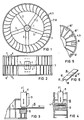
- 1 denotes the hub of a fan wheel which can be pushed onto a shaft (not shown) for the purpose of rotation.
- spokes 2 extend from the hub 1, for example five spokes 2, which support an annular disk 3 concentrically to the hub 1 at a distance.
- the ring disk 3 is a carrier of a plurality of concave lamellae 4 and 5.
- the lamellae 4 and 5 are each arranged alternately offset on both sides of the ring disk; they are each fixed on their outer peripheral edge by a concentric ring 7 and 8, while their inner tear-off edge is exposed.
- the fan wheel thus results overall as a stable component.
- fan wheel shown in FIG. 1 and FIG. 2 is only to be considered as an example.
- Alternative fan wheels can be formed from a hub 1 with an annular disk 3 directly attached to it for only one row of fins 4.
- the fins 4 can also directly as curved blades attached to the hub.
- Such fan wheels are known in principle in the axial or radial design from the prior art. They consist in particular of thermoplastic material and are advantageously mass-produced by injection molding. Due to the inevitable inaccuracies in mass production, fan wheels of this type usually have an imbalance, which must be eliminated as part of quality assurance before the parts are released.
- the compensating element is advantageously formed from the same material as the fan wheel and is available as a band-shaped semifinished product from which elements of a suitable length are separated. Since this material has a lower specific weight than metal, larger and therefore easier to handle elements can be used with the same weight.
- FIG. 3 and FIG. 4 a fan wheel 1 to 8 according to FIG. 1 and FIG. 2 is indicated in two different positions together with a tool for ultrasonic welding.
- a sonotrode 11 and an associated anvil 12 can be seen, which are arranged on both sides of the annular disk 3 in FIG. 3 and a lamella 4 on both sides in FIG.
- the anvil 12 defines a support for ultrasonic welding and the sonotrode 11 the associated ultrasonic tool, which can be displaced in the vertical direction and can activate a welding process by pressure on the one hand and vertical ultrasonic vibrations with a predetermined frequency and amplitude as well as power.
- a frequency of 20 kHz an amplitude of 25 ⁇ m and a power of 1000 W are used.
- the sonotrode 11 is fed perpendicular to the welding plane.
- the anvil 12 is adapted with its contact surface to the contour of the welding plane.
- a compensating element 15 is inserted between the sonotrode 11 and the surface of the ring disk 3 or the lamella 4 supported by the anvil 12 and is cut to a suitable length by a cutting knife 13.
- the cut part 16 can then immediately in the predetermined position by the pressure force F in connection with the ultrasound effect with the washer 3 or the lamella 4 are inseparably connected, the material of the fan wheel and the compensating element making a welded connection.
- the arrangement according to FIG. 4 in particular has the advantage that the compensating element 16 can be applied to the lamella 4 of the fan wheel in a different lateral position.
- sonotrode 11, anvil 12 and cutting knife 13 are arranged to be displaceable in the transverse direction.
- a wobble movement can also be balanced with extended fan wheels.
- different compensating elements 16 can be applied in combination to the annular disk 3 and the fins 4 or to blades of axial fan wheels according to the described method.
- parts 16 are permanently connected to the annular disk 3 or the lamella 4 as compensating elements.
- the unbalance is first automatically determined on the test station, as in the prior art, then the necessary length of the compensating element is determined and the cutting knife 13 is then controlled during the automatic feeding of the strip 15, that a defined part 16 is cut off from the strip 15 and welded directly at the predetermined location.
- an endless strip 15 according to FIG. 6 is profiled on its underside and has so-called welded roofs 17 and 18, which serve as energy direction indicators.
- welded roofs 17 and 18 serve as energy direction indicators.
- a device which is essentially functionally described with reference to FIGS. 3 and 4 can be designed as a hand-held device. However, it can also be integrated in a stationary device, which in particular comprises the test device for determining the unbalance, so that the compensating elements are welded on in an integrated manufacturing process.
- thermoplastic but of thermosetting plastic or, if applicable, of metal
- a part coated with thermoplastic or hot-melt adhesive can also be used as a compensating element. This part is connected to the fan wheel at a suitable point by thermal heating or ultrasonic welding in the manner described above. In this case, one is no longer dependent on thermoplastic as the material for the fan wheel.
Landscapes
- Engineering & Computer Science (AREA)
- General Engineering & Computer Science (AREA)
- Mechanical Engineering (AREA)
- Physics & Mathematics (AREA)
- Acoustics & Sound (AREA)
- Aviation & Aerospace Engineering (AREA)
- Lining Or Joining Of Plastics Or The Like (AREA)
Applications Claiming Priority (2)
| Application Number | Priority Date | Filing Date | Title |
|---|---|---|---|
| DE3822179 | 1988-06-30 | ||
| DE3822179 | 1988-06-30 |
Publications (3)
| Publication Number | Publication Date |
|---|---|
| EP0348846A2 true EP0348846A2 (fr) | 1990-01-03 |
| EP0348846A3 EP0348846A3 (en) | 1990-04-18 |
| EP0348846B1 EP0348846B1 (fr) | 1992-06-03 |
Family
ID=6357677
Family Applications (1)
| Application Number | Title | Priority Date | Filing Date |
|---|---|---|---|
| EP89111501A Expired - Lifetime EP0348846B1 (fr) | 1988-06-30 | 1989-06-23 | Rotor balancé d'un ventilateur ainsi que méthode et appareil pour réaliser l'équilibrage |
Country Status (2)
| Country | Link |
|---|---|
| EP (1) | EP0348846B1 (fr) |
| DE (1) | DE58901573D1 (fr) |
Cited By (11)
| Publication number | Priority date | Publication date | Assignee | Title |
|---|---|---|---|---|
| CN1074098C (zh) * | 1997-08-18 | 2001-10-31 | 台达电子工业股份有限公司 | 鼓风机的导流装置 |
| EP1571436A1 (fr) * | 2004-03-02 | 2005-09-07 | Ford Global Technologies, LLC, A subsidary of Ford Motor Company | Procede d'equilibrage d'une roue de ventilateur |
| US7024755B2 (en) * | 2003-08-28 | 2006-04-11 | Hitachi Global Storage Technologies Netherlands B.V. | Method balancing a disk pack in a hard disk drive |
| US7155807B2 (en) * | 2003-08-28 | 2007-01-02 | Hitachi Global Storage Technologies Netherlands Bv | Method of centering media disks on the hub of a spindle motor in a hard disk drive |
| US7283325B2 (en) | 2003-08-28 | 2007-10-16 | Hitachi Global Storage Technologies Netherlands Bv | Apparatus and system for centering media disks on the hub of a spindle motor in a hard disk drive |
| DE102007060479A1 (de) * | 2007-12-14 | 2009-06-25 | Ats Automation Tooling Systems Gmbh | Verfahren zum weitgehend automatischen Auswuchten eines Flügelrades und Wuchtelement zur Durchführung des Verfahrens |
| DE102008053838A1 (de) * | 2008-10-30 | 2010-06-10 | Siemens Aktiengesellschaft | Verfahren und Vorrichtung zur Wuchtung eines Rotationskörpers |
| EP3115617A4 (fr) * | 2014-03-05 | 2017-06-07 | Mitsubishi Heavy Industries, Ltd. | Élément fluide rotatif et procédé de correction de déséquilibre d'un élément fluide rotatif |
| DE102018213810A1 (de) * | 2018-08-16 | 2020-02-20 | Brose Fahrzeugteile GmbH & Co. Kommanditgesellschaft, Würzburg | Verfahren zum Ausgleich einer Unwucht einer Lüftervorrichtung sowie entsprechende Lüftervorrichtung |
| US11041502B2 (en) | 2018-01-30 | 2021-06-22 | Carrier Corporation | Double inlet backward curved blower |
| US11242864B2 (en) | 2016-10-18 | 2022-02-08 | Carrier Corporation | Asymmetric double inlet backward curved blower |
Families Citing this family (1)
| Publication number | Priority date | Publication date | Assignee | Title |
|---|---|---|---|---|
| DE102005057750A1 (de) * | 2005-12-02 | 2007-06-06 | Siemens Ag | Verfahren und Vorrichtung zum automatischen Positivwuchten eines Laufrads |
Family Cites Families (10)
| Publication number | Priority date | Publication date | Assignee | Title |
|---|---|---|---|---|
| US1762140A (en) * | 1928-06-08 | 1930-06-10 | American Manganese Steel Co | Method of and means for balancing rotary bodies having radiating blades |
| US2165069A (en) * | 1937-01-27 | 1939-07-04 | Howard T Reynolds | Fan |
| DE958147C (de) * | 1955-05-01 | 1957-02-14 | Siemens Ag | Schaufelrad fuer Geblaese, insbesondere fuer Staubsauger |
| DE1403564A1 (de) * | 1956-12-07 | 1969-08-28 | Firth Cleveland Ltd | Trommellaeufer fuer Querstromgeblaese |
| GB1001153A (en) * | 1960-09-08 | 1965-08-11 | Firth Cleveland Ltd | Improvements relating to rotors for flow machines |
| DE2019649A1 (de) * | 1970-04-23 | 1971-11-04 | Endl Gmbh & Co Elektronik | Vorrichtung zum Ablaengen von Unwuchtausgleichgewichten |
| US3694881A (en) * | 1970-06-10 | 1972-10-03 | Dov Z Glucksman | Method for manufacturing squirrel-cage rotors for fluid moving devices |
| US4079488A (en) * | 1976-01-05 | 1978-03-21 | Masao Yuda | Fan wheel for blower and apparatus for manufacturing same |
| DE2629428A1 (de) * | 1976-06-30 | 1978-01-05 | Siemens Ag | Verfahren zur auswuchtung rotierender massen, insbesondere von luefterraedern bei kfz-geblaesen |
| GB2046360A (en) * | 1979-03-31 | 1980-11-12 | Aes Plastics Ltd | Fluid impeller |
-
1989
- 1989-06-23 DE DE8989111501T patent/DE58901573D1/de not_active Expired - Lifetime
- 1989-06-23 EP EP89111501A patent/EP0348846B1/fr not_active Expired - Lifetime
Cited By (15)
| Publication number | Priority date | Publication date | Assignee | Title |
|---|---|---|---|---|
| CN1074098C (zh) * | 1997-08-18 | 2001-10-31 | 台达电子工业股份有限公司 | 鼓风机的导流装置 |
| US7024755B2 (en) * | 2003-08-28 | 2006-04-11 | Hitachi Global Storage Technologies Netherlands B.V. | Method balancing a disk pack in a hard disk drive |
| US7155807B2 (en) * | 2003-08-28 | 2007-01-02 | Hitachi Global Storage Technologies Netherlands Bv | Method of centering media disks on the hub of a spindle motor in a hard disk drive |
| US7283325B2 (en) | 2003-08-28 | 2007-10-16 | Hitachi Global Storage Technologies Netherlands Bv | Apparatus and system for centering media disks on the hub of a spindle motor in a hard disk drive |
| EP1571436A1 (fr) * | 2004-03-02 | 2005-09-07 | Ford Global Technologies, LLC, A subsidary of Ford Motor Company | Procede d'equilibrage d'une roue de ventilateur |
| DE102007060479B4 (de) * | 2007-12-14 | 2019-11-21 | Ats Automation Tooling Systems Gmbh | Verfahren zum automatischen Auswuchten eines Flügelrades |
| DE102007060479A1 (de) * | 2007-12-14 | 2009-06-25 | Ats Automation Tooling Systems Gmbh | Verfahren zum weitgehend automatischen Auswuchten eines Flügelrades und Wuchtelement zur Durchführung des Verfahrens |
| DE102008053838A1 (de) * | 2008-10-30 | 2010-06-10 | Siemens Aktiengesellschaft | Verfahren und Vorrichtung zur Wuchtung eines Rotationskörpers |
| DE102008053838B4 (de) * | 2008-10-30 | 2012-08-02 | Siemens Aktiengesellschaft | Verfahren und Vorrichtung zur Wuchtung eines Rotationskörpers |
| EP3115617A4 (fr) * | 2014-03-05 | 2017-06-07 | Mitsubishi Heavy Industries, Ltd. | Élément fluide rotatif et procédé de correction de déséquilibre d'un élément fluide rotatif |
| US10465713B2 (en) | 2014-03-05 | 2019-11-05 | Mitsubishi Heavy Industries Engine & Turbocharger, Ltd. | Rotary fluid element and method of correcting unbalance of rotary fluid element |
| US11242864B2 (en) | 2016-10-18 | 2022-02-08 | Carrier Corporation | Asymmetric double inlet backward curved blower |
| US11041502B2 (en) | 2018-01-30 | 2021-06-22 | Carrier Corporation | Double inlet backward curved blower |
| US11873831B2 (en) | 2018-01-30 | 2024-01-16 | Carrier Corporation | Double inlet backward curved blower |
| DE102018213810A1 (de) * | 2018-08-16 | 2020-02-20 | Brose Fahrzeugteile GmbH & Co. Kommanditgesellschaft, Würzburg | Verfahren zum Ausgleich einer Unwucht einer Lüftervorrichtung sowie entsprechende Lüftervorrichtung |
Also Published As
| Publication number | Publication date |
|---|---|
| EP0348846A3 (en) | 1990-04-18 |
| EP0348846B1 (fr) | 1992-06-03 |
| DE58901573D1 (de) | 1992-07-09 |
Similar Documents
| Publication | Publication Date | Title |
|---|---|---|
| EP0348846B1 (fr) | Rotor balancé d'un ventilateur ainsi que méthode et appareil pour réaliser l'équilibrage | |
| DE69810196T2 (de) | Herstellung oder Reparierung einer beschaufelten Scheibe durch Linearreibschweissen | |
| DE69301740T2 (de) | Schleifartikel und Verfahren | |
| DE19959348A1 (de) | Schleifscheibe für die Verwendung in einer Schleifvorrichtung | |
| DE69311676T2 (de) | Verfahren zum Schweissen von beschaufelte Rotorscheiben mit einem Energiestrahl hoher Leistungsdichte | |
| DE3823509C1 (fr) | ||
| DE3541347C1 (de) | Faecherstirnschleifscheibe | |
| DE2741636C3 (de) | Riemenscheibe und Verfahren zu ihrer Herstellung | |
| DE69731001T2 (de) | Wechselstromgenerator für fahrzeug | |
| EP1065022B1 (fr) | Procédé et dispositif de fixation de pales | |
| CH628474A5 (de) | Rotoranordnung fuer schrittschaltmotoren. | |
| DE1402836A1 (de) | Verfahren zur Herstellung von Rotoren,z.B. fuer Geblaese | |
| DE102008025554A1 (de) | Lamellenschleifscheibe | |
| EP1266724A1 (fr) | Disque abrasif de meulage, produit intermédiaire et procédé de fabrication d'un tel disque abrasif | |
| DE3630257A1 (de) | Stuetzscheibe fuer die rotorwelle einer oe-spinnmaschine | |
| DE3735766A1 (de) | Verfahren und vorrichtung zur herstellung von buerstendichtungen | |
| DE2416299A1 (de) | Buchschneidmaschine | |
| DE4439132A1 (de) | Verfahren und Vorrichtung zur Herstellung von Schleif- bzw. Polierwerkzeugen | |
| DE4229154A1 (de) | Stützscheibe für eine Stützscheibenlagerung eines Spinnrotors | |
| DE3913960A1 (de) | Vorrichtung und verfahren zur herstellung eines schleifwerkzeuges | |
| DE8904338U1 (de) | Radiallüfter | |
| DE2705371A1 (de) | Verfahren und vorrichtung zum herstellen einer eingekapselten umwaelzpumpe | |
| DE19748309C2 (de) | Verfahren und Vorrichtung zum Negativwuchten eines Kunststoff-Lüfterrades | |
| DE102020110005A1 (de) | Verfahren zum Befestigen eines Elements an einem drehbaren Bauteil eines Elektromotors | |
| AT202481B (de) | Schleifscheibe und Verfahren zu ihrer Herstellung |
Legal Events
| Date | Code | Title | Description |
|---|---|---|---|
| PUAI | Public reference made under article 153(3) epc to a published international application that has entered the european phase |
Free format text: ORIGINAL CODE: 0009012 |
|
| AK | Designated contracting states |
Kind code of ref document: A2 Designated state(s): DE FR GB IT |
|
| PUAL | Search report despatched |
Free format text: ORIGINAL CODE: 0009013 |
|
| AK | Designated contracting states |
Kind code of ref document: A3 Designated state(s): DE FR GB IT |
|
| 17P | Request for examination filed |
Effective date: 19900509 |
|
| 17Q | First examination report despatched |
Effective date: 19901210 |
|
| GRAA | (expected) grant |
Free format text: ORIGINAL CODE: 0009210 |
|
| AK | Designated contracting states |
Kind code of ref document: B1 Designated state(s): DE FR GB IT |
|
| PG25 | Lapsed in a contracting state [announced via postgrant information from national office to epo] |
Ref country code: IT Free format text: LAPSE BECAUSE OF FAILURE TO SUBMIT A TRANSLATION OF THE DESCRIPTION OR TO PAY THE FEE WITHIN THE PRE;WARNING: LAPSES OF ITALIAN PATENTS WITH EFFECTIVE DATE BEFORE 2007 MAY HAVE OCCURRED AT ANY TIME BEFORE 2007. THE CORRECT EFFECTIVE DATE MAY BE DIFFERENT FROM THE ONE RECORDED.SCRIBED TIME-LIMIT Effective date: 19920603 Ref country code: GB Effective date: 19920603 |
|
| REF | Corresponds to: |
Ref document number: 58901573 Country of ref document: DE Date of ref document: 19920709 |
|
| PGFP | Annual fee paid to national office [announced via postgrant information from national office to epo] |
Ref country code: DE Payment date: 19920824 Year of fee payment: 4 |
|
| EN | Fr: translation not filed | ||
| PG25 | Lapsed in a contracting state [announced via postgrant information from national office to epo] |
Ref country code: FR Effective date: 19921023 |
|
| GBV | Gb: ep patent (uk) treated as always having been void in accordance with gb section 77(7)/1977 [no translation filed] | ||
| PLBE | No opposition filed within time limit |
Free format text: ORIGINAL CODE: 0009261 |
|
| STAA | Information on the status of an ep patent application or granted ep patent |
Free format text: STATUS: NO OPPOSITION FILED WITHIN TIME LIMIT |
|
| 26N | No opposition filed | ||
| PG25 | Lapsed in a contracting state [announced via postgrant information from national office to epo] |
Ref country code: DE Effective date: 19940301 |
|
| REG | Reference to a national code |
Ref country code: FR Ref legal event code: ST |